
Small Form Factor Service Manual
Page 4
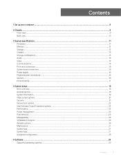
... Removing processor...52 Installing the processor...53 M.2 PCIe SSD ...54 Removing the M.2 PCIe SSD ...54 Installing the M.2 PCIe SSD...55 Power supply unit...56 Removing power supply unit or PSU...56 Installing the power supply unit or PSU...58 Speaker...60 Removing speaker...60 Installing the speaker...61 System board...62 Removing system board...62 Installing...
... Removing processor...52 Installing the processor...53 M.2 PCIe SSD ...54 Removing the M.2 PCIe SSD ...54 Installing the M.2 PCIe SSD...55 Power supply unit...56 Removing power supply unit or PSU...56 Installing the power supply unit or PSU...58 Speaker...60 Removing speaker...60 Installing the speaker...61 System board...62 Removing system board...62 Installing...

Small Form Factor Service Manual
Page 15
Screw size list Component WLAN SSD card Power supply unit (PSU) IO module Internal antenna Card reader HDD Caddy Stand-Off System board Front IO bracket M2x3.5 1 1 M3X3 2 2 M3X5 2 1 M3X6 1 6-32X1/4" 3 5 1 Removing and installing components 15 3 Removing and installing components Recommended tools The procedures in this document require the following tools: • Phillips #0 screwdriver • Phillips #1 screwdriver • Plastic scribe NOTE: The #0 screw driver is for screws 0-1 and the #1 screw driver is for screws 2-4 Screw size list Table 2.
Screw size list Component WLAN SSD card Power supply unit (PSU) IO module Internal antenna Card reader HDD Caddy Stand-Off System board Front IO bracket M2x3.5 1 1 M3X3 2 2 M3X5 2 1 M3X6 1 6-32X1/4" 3 5 1 Removing and installing components 15 3 Removing and installing components Recommended tools The procedures in this document require the following tools: • Phillips #0 screwdriver • Phillips #1 screwdriver • Plastic scribe NOTE: The #0 screw driver is for screws 0-1 and the #1 screw driver is for screws 2-4 Screw size list Table 2.

Small Form Factor Service Manual
Page 56
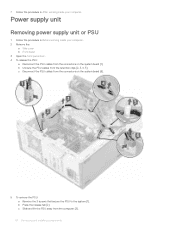
Power supply unit Removing power supply unit or PSU 1 Follow the procedure in After working inside your computer. 2 Remove the: a Side cover b Front bezel c HDD assembly d Hard drive and optical drive module e Heat sink fan 56 Removing and installing components 4 Install the: a Hard drive and optical drive module b HDD assembly c Front bezel d Side cover 5 Follow the procedure in Before working inside your computer.
Power supply unit Removing power supply unit or PSU 1 Follow the procedure in After working inside your computer. 2 Remove the: a Side cover b Front bezel c HDD assembly d Hard drive and optical drive module e Heat sink fan 56 Removing and installing components 4 Install the: a Hard drive and optical drive module b HDD assembly c Front bezel d Side cover 5 Follow the procedure in Before working inside your computer.
Small Form Factor Service Manual
Page 58
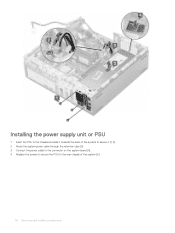
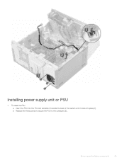
Installing the power supply unit or PSU 1 Insert the PSU in the chassis and slide it towards the back of the system to secure it [1, 2]. 2 Route the system power cable through the retention clips [3]. 3 Connect the power cable to the connector on the system board [4]. 4 Replace the screws to secure the PSU to the rear chassis of the system [5]. 58 Removing and installing components
Installing the power supply unit or PSU 1 Insert the PSU in the chassis and slide it towards the back of the system to secure it [1, 2]. 2 Route the system power cable through the retention clips [3]. 3 Connect the power cable to the connector on the system board [4]. 4 Replace the screws to secure the PSU to the rear chassis of the system [5]. 58 Removing and installing components
Tower Service Manual
Page 4
......41 Removing optional VGA module...41 Installing optional VGA module...42 Power supply unit...44 Removing power supply unit or PSU...44 Installing power supply unit or PSU...45 Intrusion switch...47 Removing intrusion switch...47 Installing intrusion switch...48 Power button...49 Removing power button...49 Installing power button...51 Speaker...53 Removing speaker...53 Installing speaker...54...
......41 Removing optional VGA module...41 Installing optional VGA module...42 Power supply unit...44 Removing power supply unit or PSU...44 Installing power supply unit or PSU...45 Intrusion switch...47 Removing intrusion switch...47 Installing intrusion switch...48 Power button...49 Removing power button...49 Installing power button...51 Speaker...53 Removing speaker...53 Installing speaker...54...

Tower Service Manual
Page 15
OptiPlex MT Component SD card reader Secured to System chassis Screw type #6.32x3.6 Quantity 1 Image WLAN M.2 PCIe SSD System board M2x3.5 1 System board 1 Type-C with DP/HDMI/VGA Cable Module System Internal Antenna System M3X3 2 2 System board Power supply unit (PSU) System chassis #6.32X1.4 9 System chassis 3 Removing and installing components 15 3 Removing and installing...
OptiPlex MT Component SD card reader Secured to System chassis Screw type #6.32x3.6 Quantity 1 Image WLAN M.2 PCIe SSD System board M2x3.5 1 System board 1 Type-C with DP/HDMI/VGA Cable Module System Internal Antenna System M3X3 2 2 System board Power supply unit (PSU) System chassis #6.32X1.4 9 System chassis 3 Removing and installing components 15 3 Removing and installing...
Tower Service Manual
Page 44
Power supply unit Removing power supply unit or PSU 1 Follow the procedure in After working inside your computer. 2 Remove the: a Side cover b Front bezel 3 Open the front panel door. 4 To release ...
Power supply unit Removing power supply unit or PSU 1 Follow the procedure in After working inside your computer. 2 Remove the: a Side cover b Front bezel 3 Open the front panel door. 4 To release ...
Tower Service Manual
Page 45
Removing and installing components 45 b Replace the three screws to secure the PSU to the computer [2] . Installing power supply unit or PSU 1 To install the PSU: a Insert the PSU into the PSU slot and slide it towards the back of the system until it clicks into place [1].
Removing and installing components 45 b Replace the three screws to secure the PSU to the computer [2] . Installing power supply unit or PSU 1 To install the PSU: a Insert the PSU into the PSU slot and slide it towards the back of the system until it clicks into place [1].
Tower Setup and specifications guide
Page 3
......12 Chipset...13 Storage combinations...13 Audio...14 Video...14 Communications...15 Ports and connectors...15 System board connectors...15 Power supply...16 Physical system dimensions...16 Security...16 Environmental...17 4 System setup...18 BIOS overview...18 General options...19 System ...information...19 Video screen options...21 Security...21 Secure boot options...22 Intel Software Guard Extensions options...23 Performance...23 Power management...24 Post behavior...25 Manageability...26 Virtualization support...26 Wireless options...26 Maintenance...27 System logs...27 System logs......
......12 Chipset...13 Storage combinations...13 Audio...14 Video...14 Communications...15 Ports and connectors...15 System board connectors...15 Power supply...16 Physical system dimensions...16 Security...16 Environmental...17 4 System setup...18 BIOS overview...18 General options...19 System ...information...19 Video screen options...21 Security...21 Secure boot options...22 Intel Software Guard Extensions options...23 Performance...23 Power management...24 Post behavior...25 Manageability...26 Virtualization support...26 Wireless options...26 Maintenance...27 System logs...27 System logs......
Tower Setup and specifications guide
Page 10
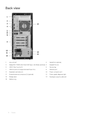
Back view 1 Line-out port 2 Serial Port (optional) 3 DisplayPort/HDMI 2.0b/VGA/USB Type-C Alt-Mode (optional) 4 DisplayPorts (2) 5 USB 3.1 Gen 1 ports (4) 6 Service tag 7 USB 2.0 ports (2) (supports SmartPower On) 8 Network port 9 Expansion card slots (4) 10 Power connector port 11 External antenna connectors (2) (optional) 12 Power supply diagnostic light 13 Release latch 14 Kensington security cable slot 15 Padlock ring 10 Chassis
Back view 1 Line-out port 2 Serial Port (optional) 3 DisplayPort/HDMI 2.0b/VGA/USB Type-C Alt-Mode (optional) 4 DisplayPorts (2) 5 USB 3.1 Gen 1 ports (4) 6 Service tag 7 USB 2.0 ports (2) (supports SmartPower On) 8 Network port 9 Expansion card slots (4) 10 Power connector port 11 External antenna connectors (2) (optional) 12 Power supply diagnostic light 13 Release latch 14 Kensington security cable slot 15 Padlock ring 10 Chassis
Tower Setup and specifications guide
Page 11
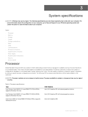
...8226; Storage combinations • Audio • Video • Communications • Ports and connectors • System board connectors • Power supply • Physical system dimensions • Security • Environmental Processor Global Standard Products (GSP) are a subset of performance. Processor ...Pentium Gold G5500 (2 Cores/4MB/4T/3.8GHz/65W); Table 2. The following specifications are not a measure of Dell's relationship products that are managed for purchase globally. Processor availability is available for availability and synchronized transitions on...
...8226; Storage combinations • Audio • Video • Communications • Ports and connectors • System board connectors • Power supply • Physical system dimensions • Security • Environmental Processor Global Standard Products (GSP) are a subset of performance. Processor ...Pentium Gold G5500 (2 Cores/4MB/4T/3.8GHz/65W); Table 2. The following specifications are not a measure of Dell's relationship products that are managed for purchase globally. Processor availability is available for availability and synchronized transitions on...

Tower Setup and specifications guide
Page 16
...) 13.8/35 6.10/15.40 10.80/27.40 20.96/9.43 Table 15. PCIe X1 slot PCIe X16 slot (wired x4) slot Power supply 2 1 (Support Standard Rev 3.0) Table 12. Power supply Input Voltage Input current (maximum) 90-264 VAC, 47 Hz/63 Hz • 260 W PSU (EPA Bronze) • 260 W PSU (EPA Platinum...
...) 13.8/35 6.10/15.40 10.80/27.40 20.96/9.43 Table 15. PCIe X1 slot PCIe X16 slot (wired x4) slot Power supply 2 1 (Support Standard Rev 3.0) Table 12. Power supply Input Voltage Input current (maximum) 90-264 VAC, 47 Hz/63 Hz • 260 W PSU (EPA Bronze) • 260 W PSU (EPA Platinum...
Tower Setup and specifications guide
Page 17
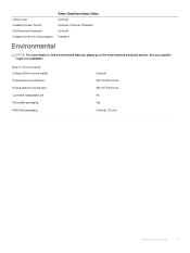
... efficient power supply 80 plus bronze certification 80 plus platinum certification Customer replaceable unit Recyclable packaging MultiPack packaging Optional 260 W EPA bronze 260 W EPA bronze No Yes Optional, US only System specifications 17 Cable Cover Chassis Intrusion Switch Dell Smartcard... Keyboard Chassis lock slot and loop support Tower/ Small form factor/ Micro Optional Optional /Optional /Standard Optional Standard Environmental NOTE: For more details on Dell environmental features, please go to the ...
... efficient power supply 80 plus bronze certification 80 plus platinum certification Customer replaceable unit Recyclable packaging MultiPack packaging Optional 260 W EPA bronze 260 W EPA bronze No Yes Optional, US only System specifications 17 Cable Cover Chassis Intrusion Switch Dell Smartcard... Keyboard Chassis lock slot and loop support Tower/ Small form factor/ Micro Optional Optional /Optional /Standard Optional Standard Environmental NOTE: For more details on Dell environmental features, please go to the ...
Tower Setup and specifications guide
Page 25
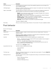
...enabled by default. Does not allows the system to enable or disable the Numlock feature when your image match screen resolution. Allows you to power on by default. The system boots quickly, unless the BIOS has been updated, memory changed, or the previous POST did not complete. &#...Post behavior Table 26. The option Enable Full Screen Logo is connected to the system in OS environment. A wakeup packet sent to AC power supply. • Disabled - POST Behavior Option Numlock LED Keyboard Errors Fast Boot Extend BIOS POST Time Full Screen Logo Warnings and Errors Description ...
...enabled by default. Does not allows the system to enable or disable the Numlock feature when your image match screen resolution. Allows you to power on by default. The system boots quickly, unless the BIOS has been updated, memory changed, or the previous POST did not complete. &#...Post behavior Table 26. The option Enable Full Screen Logo is connected to the system in OS environment. A wakeup packet sent to AC power supply. • Disabled - POST Behavior Option Numlock LED Keyboard Errors Fast Boot Extend BIOS POST Time Full Screen Logo Warnings and Errors Description ...
Micro Setup and specifications guide
Page 3
......11 Chipset...12 Storage combinations...12 Audio...13 Video...13 Communications...14 Ports and connectors...14 System board connectors...14 Power supply...15 Physical system dimensions...15 Security...15 Environmental...16 4 System setup...17 System setup...17 General options...18 System...information...18 Video screen options...19 Security...20 Secure boot options...21 Intel Software Guard Extensions options...22 Performance...22 Power management...23 Post behavior...24 Manageability...24 Virtualization support...24 Wireless options...25 Maintenance...25 System logs...26 Advanced configuration...
......11 Chipset...12 Storage combinations...12 Audio...13 Video...13 Communications...14 Ports and connectors...14 System board connectors...14 Power supply...15 Physical system dimensions...15 Security...15 Environmental...16 4 System setup...17 System setup...17 General options...18 System...information...18 Video screen options...19 Security...20 Secure boot options...21 Intel Software Guard Extensions options...22 Performance...22 Power management...23 Post behavior...24 Manageability...24 Virtualization support...24 Wireless options...25 Maintenance...25 System logs...26 Advanced configuration...

Micro Setup and specifications guide
Page 10
...8226; Chipset • Storage combinations • Audio • Video • Communications • Ports and connectors • System board connectors • Power supply • Physical system dimensions • Security • Environmental Processor Global Standard Products (GSP) are a subset of performance. They ensure the same platform...memory Intel UHD Graphics 630 Intel UHD Graphics 630 10 System specifications NOTE: Processor numbers are not a measure of Dell's relationship products that are only those required by law to change and may vary by locking in your Windows ...
...8226; Chipset • Storage combinations • Audio • Video • Communications • Ports and connectors • System board connectors • Power supply • Physical system dimensions • Security • Environmental Processor Global Standard Products (GSP) are a subset of performance. They ensure the same platform...memory Intel UHD Graphics 630 Intel UHD Graphics 630 10 System specifications NOTE: Processor numbers are not a measure of Dell's relationship products that are only those required by law to change and may vary by locking in your Windows ...

Micro Setup and specifications guide
Page 15
Power supply Table 12. Power supply Input Voltage Input current (maximum) 100-240 V, 3.2 A, 50-60 Hz • 90 W PSU (EPS Level V) Physical system dimensions Table 13. Packaging parameters Height (inches / centimeters) ...
Power supply Table 12. Power supply Input Voltage Input current (maximum) 100-240 V, 3.2 A, 50-60 Hz • 90 W PSU (EPS Level V) Physical system dimensions Table 13. Packaging parameters Height (inches / centimeters) ...

Micro Setup and specifications guide
Page 16
... is not available in all countries. Environmental Energy efficient power supply Standard Customer replaceable unit No Recyclable packaging Yes MultiPack packaging Optional, US only Temperature Ranges Temperature Gradient Maximum per 60 Min Humidity Percent Ranges Noncondensing Altitude- Environmental NOTE: For more details on Dell environmental features, please go to 95%+ (+Max dew point...
... is not available in all countries. Environmental Energy efficient power supply Standard Customer replaceable unit No Recyclable packaging Yes MultiPack packaging Optional, US only Temperature Ranges Temperature Gradient Maximum per 60 Min Humidity Percent Ranges Noncondensing Altitude- Environmental NOTE: For more details on Dell environmental features, please go to 95%+ (+Max dew point...
Micro Setup and specifications guide
Page 23
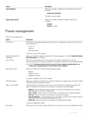
... enabled. • Disabled • Enabled in S5 only • Enabled in S4 and S5 This option is Power Off by special WLAN signals. Change the startup time by default. Allows you to AC power supply. • Disabled - Allows you to block entering to sleep (S3 state) in S4 and S5 by typing... the values in either the S4 or S5 state, that will cause the system to : • Power Off • Power On • Last Power State This option is Enabled in...
... enabled. • Disabled • Enabled in S5 only • Enabled in S4 and S5 This option is Power Off by special WLAN signals. Change the startup time by default. Allows you to AC power supply. • Disabled - Allows you to block entering to sleep (S3 state) in S4 and S5 by typing... the values in either the S4 or S5 state, that will cause the system to : • Power Off • Power On • Last Power State This option is Enabled in...
Small Form Factor Setup and specifications guide
Page 3
...Storage...11 Chipset...12 Storage combinations...12 Audio...12 Video...13 Communications...13 Ports and connectors...14 System board connectors...14 Power supply...14 Physical system dimensions...15 Security...15 Environmental...15 4 System setup...17 System setup...17 General options...17 System ...information...18 Video screen options...19 Security...20 Secure boot options...21 Intel Software Guard Extensions options...21 Performance...22 Power management...22 Post behavior...23 Virtualization support...24 Wireless options...24 Maintenance...24 System logs...25 Advanced configuration...25 5 ...
...Storage...11 Chipset...12 Storage combinations...12 Audio...12 Video...13 Communications...13 Ports and connectors...14 System board connectors...14 Power supply...14 Physical system dimensions...15 Security...15 Environmental...15 4 System setup...17 System setup...17 General options...17 System ...information...18 Video screen options...19 Security...20 Secure boot options...21 Intel Software Guard Extensions options...21 Performance...22 Power management...22 Post behavior...23 Virtualization support...24 Wireless options...24 Maintenance...24 System logs...25 Advanced configuration...25 5 ...


