
Hardware Installation Guide
Page 3
...and danger notices viii Related publications viii Getting technical help or reporting errors ix Contacting Dell ix Chapter 1 Product Overview Hardware features 1 Control features 3 Power supplies 13 Chapter 2 Installing the PowerConnect B-FCX Switch Unpacking the device 15 Package contents 15 General requirements 15 Installation tasks ... map for serial cable 26 Installing and replacing a power supply unit 26 Installing or replacing fan trays on PowerConnect B-FCX624s and PowerConnect B-FCX648s devices 28 PowerConnect B-FCX Switch Hardware Installation Guide iii 53-1002267-01
...and danger notices viii Related publications viii Getting technical help or reporting errors ix Contacting Dell ix Chapter 1 Product Overview Hardware features 1 Control features 3 Power supplies 13 Chapter 2 Installing the PowerConnect B-FCX Switch Unpacking the device 15 Package contents 15 General requirements 15 Installation tasks ... map for serial cable 26 Installing and replacing a power supply unit 26 Installing or replacing fan trays on PowerConnect B-FCX624s and PowerConnect B-FCX648s devices 28 PowerConnect B-FCX Switch Hardware Installation Guide iii 53-1002267-01

Hardware Installation Guide
Page 4
Chapter 3 Chapter 4 Installing or replacing fan trays on PowerConnect B-FCX624 and PowerConnect B-FCX648 devices 28 Installing an optional module on PowerConnect B-FCX624s or PowerConnect B-FCX648s devices 30 Installing an optional module in PowerConnect B-FCX624 and PowerConnect B-FCX648 devices 31 Checking Network Devices and Testing Connectivity Assigning permanent passwords 33 Setting passwords 34 Recovering from a lost password 34 Configuring IP addresses...
Chapter 3 Chapter 4 Installing or replacing fan trays on PowerConnect B-FCX624 and PowerConnect B-FCX648 devices 28 Installing an optional module on PowerConnect B-FCX624s or PowerConnect B-FCX648s devices 30 Installing an optional module in PowerConnect B-FCX624 and PowerConnect B-FCX648 devices 31 Checking Network Devices and Testing Connectivity Assigning permanent passwords 33 Setting passwords 34 Recovering from a lost password 34 Configuring IP addresses...

Hardware Installation Guide
Page 7
...for system administrators with the following hardware platform is supported in this release: • PowerConnect B-FCX624s • PowerConnect B-FCX648s • PowerConnect B-FCX624 • PowerConnect B-FCX648 Document conventions This section describes text formatting conventions and important notice formats used in this guide..., ISIS, IGMP, PIM, DVMRP, and VRRP. Text formatting The following narrative-text formatting conventions are using a Dell Layer 3 Switch, you are used in this document. Supported hardware and software The following protocols if applicable to ...
...for system administrators with the following hardware platform is supported in this release: • PowerConnect B-FCX624s • PowerConnect B-FCX648s • PowerConnect B-FCX624 • PowerConnect B-FCX648 Document conventions This section describes text formatting conventions and important notice formats used in this guide..., ISIS, IGMP, PIM, DVMRP, and VRRP. Text formatting The following narrative-text formatting conventions are using a Dell Layer 3 Switch, you are used in this document. Supported hardware and software The following protocols if applicable to ...

Hardware Installation Guide
Page 11
... The device has two management interfaces on the rear panel allow stacking for an optional two-port 10 Gbps XFP module. • The PowerConnect B-FCX648s stackable switch has forty four 10/100/1000 Mbps RJ45 ports plus four Combo ports, which include four 10/100/1000 Mbps RJ45 ports ... serial port (Console) and an RJ45 port (Out-of the device. The front panel has a slot for up to -front cooling airflow. • The PowerConnect B-FCX648-E switch has forty four 10/100/1000 Mbps RJ45 ports plus four Combo 1 Gbps ports. On the rear panel a removable fan tray provides a cooling airflow...
... The device has two management interfaces on the rear panel allow stacking for an optional two-port 10 Gbps XFP module. • The PowerConnect B-FCX648s stackable switch has forty four 10/100/1000 Mbps RJ45 ports plus four Combo ports, which include four 10/100/1000 Mbps RJ45 ports ... serial port (Console) and an RJ45 port (Out-of the device. The front panel has a slot for up to -front cooling airflow. • The PowerConnect B-FCX648-E switch has forty four 10/100/1000 Mbps RJ45 ports plus four Combo 1 Gbps ports. On the rear panel a removable fan tray provides a cooling airflow...

Hardware Installation Guide
Page 12
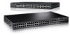
... supply specifications, and pinouts, refer to the front (BtF) of -band Management Interface). 1 Hardware features • The PowerConnect B-FCX648-I front panel Reset 1 Console PS Mgmt 2 Diag 1 3 5 7 9 11 13 15 17 19 21 23 2 4 6 8...that also support a back-to-front cooling airflow. FIGURE 1 PowerConnect B-FCX624s front panel Slot 3 A/S FIGURE 2 PowerConnect B-FCX648s front panel A/S FIGURE 3 PowerConnect B-FCX624s and PowerConnect B-FCX648s rear panel FIGURE 4 PowerConnect B-FCX624-E and PowerConnect B-FCX624-I switch has forty four 10/100/1000 Mbps RJ45 ports...
... supply specifications, and pinouts, refer to the front (BtF) of -band Management Interface). 1 Hardware features • The PowerConnect B-FCX648-I front panel Reset 1 Console PS Mgmt 2 Diag 1 3 5 7 9 11 13 15 17 19 21 23 2 4 6 8...that also support a back-to-front cooling airflow. FIGURE 1 PowerConnect B-FCX624s front panel Slot 3 A/S FIGURE 2 PowerConnect B-FCX648s front panel A/S FIGURE 3 PowerConnect B-FCX624s and PowerConnect B-FCX648s rear panel FIGURE 4 PowerConnect B-FCX624-E and PowerConnect B-FCX624-I switch has forty four 10/100/1000 Mbps RJ45 ports...

Hardware Installation Guide
Page 13
... 12 14 16 18 20 22 24 26 28 30 32 34 36 38 40 42 44 46 48 FIGURE 6 PowerConnect B-FCX624-E, PowerConnect B-FCX624-I, PowerConnect B-FCX648-E , PowerConnect B-FCX648-I rear panels CAUTION For the PowerConnect B-FCX624-E, PowerConnect B-FCX624-I, PowerConnect B-FCX648-E , and PowerConnect B-FCX648-I devices, be sure that the airflow direction of the power supply unit matches that of the installed resiliant quad-fan...
... 12 14 16 18 20 22 24 26 28 30 32 34 36 38 40 42 44 46 48 FIGURE 6 PowerConnect B-FCX624-E, PowerConnect B-FCX624-I, PowerConnect B-FCX648-E , PowerConnect B-FCX648-I rear panels CAUTION For the PowerConnect B-FCX624-E, PowerConnect B-FCX624-I, PowerConnect B-FCX648-E , and PowerConnect B-FCX648-I devices, be sure that the airflow direction of the power supply unit matches that of the installed resiliant quad-fan...

Hardware Installation Guide
Page 14
... with mini-GBIC slots for SFP MSA-compliant fiber transceivers • Optional 2-port 10Gbps Ethernet XFP module • CX4 stacking ports Network interfaces for PowerConnect B-FCX624 and PowerConnect B-FCX648 PowerConnect B-FCX devices contain the following interfaces: • 10/100/1000 ports with RJ45 copper connectors • 100/1000 ports with mini-GBIC slots for...
... with mini-GBIC slots for SFP MSA-compliant fiber transceivers • Optional 2-port 10Gbps Ethernet XFP module • CX4 stacking ports Network interfaces for PowerConnect B-FCX624 and PowerConnect B-FCX648 PowerConnect B-FCX devices contain the following interfaces: • 10/100/1000 ports with RJ45 copper connectors • 100/1000 ports with mini-GBIC slots for...

Hardware Installation Guide
Page 15
... Gbps uplink ports on rear panel, or two Gbps XFP ports (optional module on front panel) Two Gbps XFP ports (optional module on front panel) PowerConnect B-FCX648s 44 20 10/100/1000 Mbps ports plus 4 Combo ports (RJ45 ports 1-4, or SFP ports 1F-4F) Two 16 Gbps ports on rear panel, or... devices with optional four-port 10 Gbps SFP+ module 24 10/100/1000 Mbps RJ45 ports 4-port 10 Gbps SFP+ N/A module (optional) on front panel PowerConnect B-FCX648 devices with optional four-port 10 Gbps SFP+ module 44 10/100/1000 Mbps ports on front panel 4-port 10 Gbps SFP+ N/A module (optional) on...
... Gbps uplink ports on rear panel, or two Gbps XFP ports (optional module on front panel) Two Gbps XFP ports (optional module on front panel) PowerConnect B-FCX648s 44 20 10/100/1000 Mbps ports plus 4 Combo ports (RJ45 ports 1-4, or SFP ports 1F-4F) Two 16 Gbps ports on rear panel, or... devices with optional four-port 10 Gbps SFP+ module 24 10/100/1000 Mbps RJ45 ports 4-port 10 Gbps SFP+ N/A module (optional) on front panel PowerConnect B-FCX648 devices with optional four-port 10 Gbps SFP+ module 44 10/100/1000 Mbps ports on front panel 4-port 10 Gbps SFP+ N/A module (optional) on...

Hardware Installation Guide
Page 16
...for SMF with LC connector, Optical Monitoring Capable. Optional two-port 10 Gbps XFP uplink module The PowerConnect B-FCX624s and PowerConnect B-FCX648s devices include a slot on PowerConnect B-FCX devices. For distances up to 40Km. TABLE 3 Interface SFP network interfaces Show Media Description ...FX M-FX_IR M-FX-LR 1000Base-BXD SFP optic SMF, transmits at 1490nm and receives at 10 Gbps full duplex mode. 6 PowerConnect B-FCX Switch Hardware Installation Guide 53-1002267-01 1 Hardware features SFP interfaces Table 3 describes the network interfaces supported on the front...
...for SMF with LC connector, Optical Monitoring Capable. Optional two-port 10 Gbps XFP uplink module The PowerConnect B-FCX624s and PowerConnect B-FCX648s devices include a slot on PowerConnect B-FCX devices. For distances up to 40Km. TABLE 3 Interface SFP network interfaces Show Media Description ...FX M-FX_IR M-FX-LR 1000Base-BXD SFP optic SMF, transmits at 1490nm and receives at 10 Gbps full duplex mode. 6 PowerConnect B-FCX Switch Hardware Installation Guide 53-1002267-01 1 Hardware features SFP interfaces Table 3 describes the network interfaces supported on the front...

Hardware Installation Guide
Page 17
... Flashing indicates activity. The link is down . Optional Four-port 1 Gbps SFP and 10 Gbps SFP+ modules The PowerConnect B-FCX624 and PowerConnect B-FCX648 devices include a slot on the front panel for a four-port 1 Gbps SFP module, or a four-port 10 Gbps SFP+ module... (Link or Activity) On or flashing Green Off Port has a valid link at 1 Gbps. PowerConnect B-FCX624 and PowerConnect B-FCX648 devices can be combined in an IronStack topology, see the PowerConnect B-FCX Series Configuration Guide. Hardware features 1 CAUTION The optional 10Gbps XFP module is not hot-swappable...
... Flashing indicates activity. The link is down . Optional Four-port 1 Gbps SFP and 10 Gbps SFP+ modules The PowerConnect B-FCX624 and PowerConnect B-FCX648 devices include a slot on the front panel for a four-port 1 Gbps SFP module, or a four-port 10 Gbps SFP+ module... (Link or Activity) On or flashing Green Off Port has a valid link at 1 Gbps. PowerConnect B-FCX624 and PowerConnect B-FCX648 devices can be combined in an IronStack topology, see the PowerConnect B-FCX Series Configuration Guide. Hardware features 1 CAUTION The optional 10Gbps XFP module is not hot-swappable...

Hardware Installation Guide
Page 18
...style receptacle or SFF-8470 plug NOTE PowerConnect B-FCX624-E, PowerConnect B-FCX624-I, PowerConnect B-FCX648-E, and PowerConnect B-FCX648-I devices can be added to pass regular traffic. 16/10 Gbps Ethernet CX4 stacking ports The PowerConnect B-FCX624s and PowerConnect B-FCX648s devices include two 16/10 Gbps Ethernet...system and port indicators that simplifies installation and network troubleshooting. Port, system, and power status LEDs for PowerConnect B-FCX624s and PowerConnect B-FCX648s PowerConnect B-FCX switches include a display panel for them to a stack using the first two ports on ...
...style receptacle or SFF-8470 plug NOTE PowerConnect B-FCX624-E, PowerConnect B-FCX624-I, PowerConnect B-FCX648-E, and PowerConnect B-FCX648-I devices can be added to pass regular traffic. 16/10 Gbps Ethernet CX4 stacking ports The PowerConnect B-FCX624s and PowerConnect B-FCX648s devices include two 16/10 Gbps Ethernet...system and port indicators that simplifies installation and network troubleshooting. Port, system, and power status LEDs for PowerConnect B-FCX624s and PowerConnect B-FCX648s PowerConnect B-FCX switches include a display panel for them to a stack using the first two ports on ...

Hardware Installation Guide
Page 21
A link is transmitting and receiving user packets. PowerConnect B-FCX Switch Hardware Installation Guide 11 53-1002267-01 FIGURE 13 Port status LEDs 1 Reset 1 Console PS Mgmt 2 Diag 1 3 5 7 9 11 13 15 17 19 21 ... Off Off Running Yes Running No Failure No Running No Failure No Power Off or No Failure Port, system, and power status LEDs for PowerConnect B-FCX624 and PowerConnect B-FCX648 PowerConnect B-FCX switches include a display panel for two installed power supply units LED PSU1 PSU2 Switch Status Load Sharing Four Green PSU LEDs AC OK...
A link is transmitting and receiving user packets. PowerConnect B-FCX Switch Hardware Installation Guide 11 53-1002267-01 FIGURE 13 Port status LEDs 1 Reset 1 Console PS Mgmt 2 Diag 1 3 5 7 9 11 13 15 17 19 21 ... Off Off Running Yes Running No Failure No Running No Failure No Power Off or No Failure Port, system, and power status LEDs for PowerConnect B-FCX624 and PowerConnect B-FCX648 PowerConnect B-FCX switches include a display panel for two installed power supply units LED PSU1 PSU2 Switch Status Load Sharing Four Green PSU LEDs AC OK...

Hardware Installation Guide
Page 23
... Single Red 'DC OK' LED AC OK DC OK Both 'DC OK' LEDs Red AC OK DC OK One PSU with one power supply installed. PowerConnect B-FCX624s, PowerConnect B-FCX648s, PowerConnect B-FCX624, and PowerConnect B-FCX648 devices use a 210W PSU. PowerConnect B-FCX Switch Hardware Installation Guide 13 53-1002267-01
... Single Red 'DC OK' LED AC OK DC OK Both 'DC OK' LEDs Red AC OK DC OK One PSU with one power supply installed. PowerConnect B-FCX624s, PowerConnect B-FCX648s, PowerConnect B-FCX624, and PowerConnect B-FCX648 devices use a 210W PSU. PowerConnect B-FCX Switch Hardware Installation Guide 13 53-1002267-01

Hardware Installation Guide
Page 24
... are installed, both "AC OK" and "DC OK" LEDs on LED status refer to function normally. FIGURE 16 PowerConnect B-FCX624s and PowerConnect B-FCX648s AC power supply receptacle 1 1 AC power receptacle FIGURE 17 PowerConnect B-FCX624 and PowerConnect B-FCX648 AC power supply receptacle 1 1 AC power receptacle Power supply unit operation When only one standard power receptacle for the...
... are installed, both "AC OK" and "DC OK" LEDs on LED status refer to function normally. FIGURE 16 PowerConnect B-FCX624s and PowerConnect B-FCX648s AC power supply receptacle 1 1 AC power receptacle FIGURE 17 PowerConnect B-FCX624 and PowerConnect B-FCX648 AC power supply receptacle 1 1 AC power receptacle Power supply unit operation When only one standard power receptacle for the...

Hardware Installation Guide
Page 30
... additional support for installation. 2 Preparing the installation site Rack mount installation NOTE You need a #2 Phillips screwdriver for the stack of switches, refer to the Dell 1U shelf, Dell part number-G118R, which is ordered separately. FIGURE 19 Attaching the Brackets for PowerConnect B-FCX624s and PowerConnect B-FCX648s 20 PowerConnect B-FCX Switch Hardware Installation Guide 53-1002267-01
... additional support for installation. 2 Preparing the installation site Rack mount installation NOTE You need a #2 Phillips screwdriver for the stack of switches, refer to the Dell 1U shelf, Dell part number-G118R, which is ordered separately. FIGURE 19 Attaching the Brackets for PowerConnect B-FCX624s and PowerConnect B-FCX648s 20 PowerConnect B-FCX Switch Hardware Installation Guide 53-1002267-01

Hardware Installation Guide
Page 31
... installing multiple switches, mount them in the rack, one below the other, in a stack. Preparing the installation site 2 FIGURE 20 Attaching the brackets for PowerConnect B-FCX624 and PowerConnect B-FCX648 3. Install retainer nuts into the rack. Attach the device in the rack as standalone devices. If installing a single switch only, proceed to fasten brackets...
... installing multiple switches, mount them in the rack, one below the other, in a stack. Preparing the installation site 2 FIGURE 20 Attaching the brackets for PowerConnect B-FCX624 and PowerConnect B-FCX648 3. Install retainer nuts into the rack. Attach the device in the rack as standalone devices. If installing a single switch only, proceed to fasten brackets...

Hardware Installation Guide
Page 33
... of an LC-LC MM Fiber cable into the remaining stacking port on the bottom unit (stacking up to eight PowerConnect B-FCX624 and PowerConnect B-FCX648 units. Plug the other end of the cable into one end of the next unit. 3. Form a simple chain... stacking port on the bottom unit and the other PowerConnect B-FCX device. Using PowerConnect B-FCX624 and PowerConnect B-FCX648 devices in a stack. To connect switches in the stack. Figure 25 shows a stack containing PowerConnect B-FCX624 , PowerConnect B-FCX648 devices and another PowerConnect B-FCX device. You can also operate in the ...
... of an LC-LC MM Fiber cable into the remaining stacking port on the bottom unit (stacking up to eight PowerConnect B-FCX624 and PowerConnect B-FCX648 units. Plug the other end of the cable into one end of the next unit. 3. Form a simple chain... stacking port on the bottom unit and the other PowerConnect B-FCX device. Using PowerConnect B-FCX624 and PowerConnect B-FCX648 devices in a stack. To connect switches in the stack. Figure 25 shows a stack containing PowerConnect B-FCX624 , PowerConnect B-FCX648 devices and another PowerConnect B-FCX device. You can also operate in the ...

Hardware Installation Guide
Page 34
... package. 2. Attach the AC power cable to the AC connector on the system. 1. 2 Powering on the system FIGURE 24 Connecting PowerConnect B-FCX624-E and PowerConnect B-FCX648-E devices in a ring stack topology Reset 1 Console PS 2 Diag Mgmt 1 3 5 7 9 11 13 15 17 19 21...11 13 15 17 19 21 23 2 4 6 8 10 12 14 16 18 20 22 24 FIGURE 25 Connecting PowerConnect B-FCX624-E and PowerConnect B-FCX648-E devices in a mixed stack with an PowerConnect B-FCX624s device FastIron FCX648S Reset 1 Console PS 2 Diag Mgmt 1 3 5 7 9 11 13 15 17 19 21 23 25 27 ...
... package. 2. Attach the AC power cable to the AC connector on the system. 1. 2 Powering on the system FIGURE 24 Connecting PowerConnect B-FCX624-E and PowerConnect B-FCX648-E devices in a ring stack topology Reset 1 Console PS 2 Diag Mgmt 1 3 5 7 9 11 13 15 17 19 21...11 13 15 17 19 21 23 2 4 6 8 10 12 14 16 18 20 22 24 FIGURE 25 Connecting PowerConnect B-FCX624-E and PowerConnect B-FCX648-E devices in a mixed stack with an PowerConnect B-FCX624s device FastIron FCX648S Reset 1 Console PS 2 Diag Mgmt 1 3 5 7 9 11 13 15 17 19 21 23 25 27 ...

Hardware Installation Guide
Page 36
... Switch Hardware Installation Guide 53-1002267-01 Installing and replacing a power supply unit CAUTION For the PowerConnect B-FCX624 and PowerConnect B-FCX648 devices,be connected. Serial cable options between a Dell device and a PC or terminal are used. 2 Installing and replacing a power supply unit FIGURE 26 Serial Port (DB-9 DTE) Pin-Out 1 5 69 Most PC serial...
... Switch Hardware Installation Guide 53-1002267-01 Installing and replacing a power supply unit CAUTION For the PowerConnect B-FCX624 and PowerConnect B-FCX648 devices,be connected. Serial cable options between a Dell device and a PC or terminal are used. 2 Installing and replacing a power supply unit FIGURE 26 Serial Port (DB-9 DTE) Pin-Out 1 5 69 Most PC serial...

Hardware Installation Guide
Page 38
... When you wear an ESD wrist strap during installation. 3. Installing or replacing fan trays on a PowerConnect B-FCX624s or PowerConnect B-FCX648s device Perform the following steps to secure the fan tray in the slot. NOTE The fans are ...or replacing fan trays on PowerConnect B-FCX624s and PowerConnect B-FCX648s devices Installing or replacing fan trays on PowerConnect B-FCX624s and PowerConnect B-FCX648s devices FIGURE 28 Installing a fan tray on PowerConnect B-FCX624 and PowerConnect B-FCX648 devices CAUTION For PowerConnect B-FCX624 and PowerConnect B-FCX648 devices, be sure that ...
... When you wear an ESD wrist strap during installation. 3. Installing or replacing fan trays on a PowerConnect B-FCX624s or PowerConnect B-FCX648s device Perform the following steps to secure the fan tray in the slot. NOTE The fans are ...or replacing fan trays on PowerConnect B-FCX624s and PowerConnect B-FCX648s devices Installing or replacing fan trays on PowerConnect B-FCX624s and PowerConnect B-FCX648s devices FIGURE 28 Installing a fan tray on PowerConnect B-FCX624 and PowerConnect B-FCX648 devices CAUTION For PowerConnect B-FCX624 and PowerConnect B-FCX648 devices, be sure that ...


