User Manual
Page 30
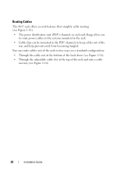
...28 Installation Guide Routing Cables The 48-U rack offers several features that simplify cable routing (see Figure 1-16). • The power distribution unit (PDU) channels in each rack flange allow you to route power cables to the systems mounted in the rack. • Cable clips can route cables out of the rack... in the PDU channels to keep cables out of the rack and into a cable raceway (see Figure 1-16). • Through the adjustable cable slot at the top of ...
...28 Installation Guide Routing Cables The 48-U rack offers several features that simplify cable routing (see Figure 1-16). • The power distribution unit (PDU) channels in each rack flange allow you to route power cables to the systems mounted in the rack. • Cable clips can route cables out of the rack... in the PDU channels to keep cables out of the rack and into a cable raceway (see Figure 1-16). • Through the adjustable cable slot at the top of ...

User Manual
Page 31
Cable-Routing Options 1 2 3 4 5 1 cable raceway 3 cable clips 5 bottom cable exit 2 top cable slot 4 PDU channels (2 per side) Opening and Closing the Top Cable Slot The top cable slot in the rack can be used for routing cables up to a cable raceway. 1 Open the back doors. 2 Loosen the wingnuts underneath the cable slot cover (see Figure 1-17). Figure 1-16. Installation Guide 29
Cable-Routing Options 1 2 3 4 5 1 cable raceway 3 cable clips 5 bottom cable exit 2 top cable slot 4 PDU channels (2 per side) Opening and Closing the Top Cable Slot The top cable slot in the rack can be used for routing cables up to a cable raceway. 1 Open the back doors. 2 Loosen the wingnuts underneath the cable slot cover (see Figure 1-17). Figure 1-16. Installation Guide 29

Dell PowerEdge 2420 Rack Installation Guide
Page 25
... doors (see Figure 1-14) • Through the adjustable cable slot at the top of the way and help prevent cords from becoming tangled. You can be mounted in the PDU channels to the systems mounted in the rack. • Cable clips can route cables out of the rack in each rack flange allow... you to route power cables to keep cables out of the rack and into a cable raceway (see Figure 1-14).
... doors (see Figure 1-14) • Through the adjustable cable slot at the top of the way and help prevent cords from becoming tangled. You can be mounted in the PDU channels to the systems mounted in the rack. • Cable clips can route cables out of the rack in each rack flange allow... you to route power cables to keep cables out of the rack and into a cable raceway (see Figure 1-14).

Dell PowerEdge 2420 Rack Installation Guide
Page 26
Cable-Routing Options 1 2 3 4 1 cable raceway 3 cable clips 5 bottom cable exit 5 2 top cable slot 4 PDU channels (2 per side) 24 Installation Guide Figure 1-14.
Cable-Routing Options 1 2 3 4 1 cable raceway 3 cable clips 5 bottom cable exit 5 2 top cable slot 4 PDU channels (2 per side) 24 Installation Guide Figure 1-14.

User Manual
Page 26
Cable-Routing Options 2 1 1 cable-routing channels (4) 3 cable exit route 2 cable raceway 24 Dell™ PowerEdge™ 4210 Installation Guide Routing Cables The 42-U rack offers several features that simplify cable routing (see Figure 1-11). • Four cable-routing channels in each rack flange allow you to route power distribution unit (PDU) power cables to the systems mounted in the rack. • Cable clips mounted on the frame uprights keep cables out of the way and help prevent cords from becoming tangled. Figure 1-11.
Cable-Routing Options 2 1 1 cable-routing channels (4) 3 cable exit route 2 cable raceway 24 Dell™ PowerEdge™ 4210 Installation Guide Routing Cables The 42-U rack offers several features that simplify cable routing (see Figure 1-11). • Four cable-routing channels in each rack flange allow you to route power distribution unit (PDU) power cables to the systems mounted in the rack. • Cable clips mounted on the frame uprights keep cables out of the way and help prevent cords from becoming tangled. Figure 1-11.

Cabling PowerEdge R815
Page 5
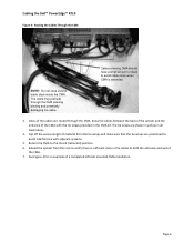
... shown in the CMA kit. 5. NOTE: For guidelines on how to route cables within the rack, refer to the Dell Best Practices Guide for details on power supply replacement. Clip off the excess length of the power supplies (left-side mount) is sufficient ... Mounting Instructions 1. Route the cables through the CMA while avoiding twisting the cables. Page 3 Cable Routing Procedures for Dell™ PowerEdge™ R815 Systems 1.2 Routing the Power Cables Through the Strain Reliefs After you have installed the tray and cables, route the power cables through the strain reliefs located on...
... shown in the CMA kit. 5. NOTE: For guidelines on how to route cables within the rack, refer to the Dell Best Practices Guide for details on power supply replacement. Clip off the excess length of the power supplies (left-side mount) is sufficient ... Mounting Instructions 1. Route the cables through the CMA while avoiding twisting the cables. Page 3 Cable Routing Procedures for Dell™ PowerEdge™ R815 Systems 1.2 Routing the Power Cables Through the Strain Reliefs After you have installed the tray and cables, route the power cables through the strain reliefs located on...

Cabling PowerEdge R815
Page 7
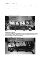
...the rails without causing damage to the closed (retracted) position. 6. Once you have routed all illustrations) provided in all the cables through the CMA. Page 5 Clip off the excess length of the CMA as to avoid interference with adjacent systems. Return the CMA to the dongle. Make sure...the heads of the CMA. Extend the system out of the rack to the attachment brackets on the CMA to the outside the basket for Dell™ PowerEdge™ R815 Systems 1.5 Right-Side Mounting Instructions 1. Use the hook and loop straps on the rails. 2. Figure 5: Right-Side Mounted ...
...the rails without causing damage to the closed (retracted) position. 6. Once you have routed all illustrations) provided in all the cables through the CMA. Page 5 Clip off the excess length of the CMA as to avoid interference with adjacent systems. Return the CMA to the dongle. Make sure...the heads of the CMA. Extend the system out of the rack to the attachment brackets on the CMA to the outside the basket for Dell™ PowerEdge™ R815 Systems 1.5 Right-Side Mounting Instructions 1. Use the hook and loop straps on the rails. 2. Figure 5: Right-Side Mounted ...

Cabling PowerEdge R810
Page 5
...so as shown in Figure 2. Cable Routing Procedures for Dell™ PowerEdge™ R810 Systems 1.2 Routing the Power Cables Through the Strain Reliefs After you have installed the tray and cables, route the power cables through the strain reliefs located ...on both CMA housings to the Dell Best Practices Guide for details on the rear left -side mounted CMA installation. Page 3 Clip...
...so as shown in Figure 2. Cable Routing Procedures for Dell™ PowerEdge™ R810 Systems 1.2 Routing the Power Cables Through the Strain Reliefs After you have installed the tray and cables, route the power cables through the strain reliefs located ...on both CMA housings to the Dell Best Practices Guide for details on the rear left -side mounted CMA installation. Page 3 Clip...

Cabling PowerEdge R810
Page 7
...the dongle. Install the CMA on the CMA to be too short for Dell™ PowerEdge™ R810 Systems 1.5 Right-Side Mounting Instructions 1. Make sure that there is sufficient slack in all the cables through the CMA, dress the cable slack between the back of the system and the entrance of the rails ...without causing damage to the outside the basket for Right-Side Mounting. Clip off the excess length of material from the tie wraps. Route the cables through the CMA. Use the hook and loop straps on the rear right side of the tie wraps ...
...the dongle. Install the CMA on the CMA to be too short for Dell™ PowerEdge™ R810 Systems 1.5 Right-Side Mounting Instructions 1. Make sure that there is sufficient slack in all the cables through the CMA, dress the cable slack between the back of the system and the entrance of the rails ...without causing damage to the outside the basket for Right-Side Mounting. Clip off the excess length of material from the tie wraps. Route the cables through the CMA. Use the hook and loop straps on the rear right side of the tie wraps ...

Cabling PowerEdge R715
Page 5
...the CMA must be disconnected, to some extent, in all the cables through the CMA while avoiding twisting the cables. Refer to the Dell Best Practices Guide for Rack Enclosures white paper. 1.4 Left-Side Mounting Instructions 1. Clip off the excess length of the CMA. Make sure that there...positioned so as shown in the CMA kit. 5. Cable Routing Procedures for Dell™ PowerEdge™ R715 Systems 1.2 Routing the Power Cables Through the Strain Reliefs After you have installed the tray and cables, route the power cables through the strain reliefs located on the power supply ...
...the CMA must be disconnected, to some extent, in all the cables through the CMA while avoiding twisting the cables. Refer to the Dell Best Practices Guide for Rack Enclosures white paper. 1.4 Left-Side Mounting Instructions 1. Clip off the excess length of the CMA. Make sure that there...positioned so as shown in the CMA kit. 5. Cable Routing Procedures for Dell™ PowerEdge™ R715 Systems 1.2 Routing the Power Cables Through the Strain Reliefs After you have installed the tray and cables, route the power cables through the strain reliefs located on the power supply ...

Cabling PowerEdge R715
Page 7
... be placed in the CMA kit. 5. Clip off the excess length of the CMA using the tie wraps (shown in yellow in all illustrations) provided in the CMA basket. Cable Routing Procedures for the dongle to be too short for Dell™ PowerEdge™ R715 Systems 1.5 Right-Side Mounting ...Instructions 1. Once you have routed all the cables through the CMA. Extend the system out of the rack to...
... be placed in the CMA kit. 5. Clip off the excess length of the CMA using the tie wraps (shown in yellow in all illustrations) provided in the CMA basket. Cable Routing Procedures for the dongle to be too short for Dell™ PowerEdge™ R715 Systems 1.5 Right-Side Mounting ...Instructions 1. Once you have routed all the cables through the CMA. Extend the system out of the rack to...
Cabling PowerEdge R710
Page 6
...with adjacent systems. 5. Cabling the Dell™ PowerEdge™ R710 Figure 3: Routing the Cables Through the CMA Cables entering CMA should have a small amount of material from the rack to the closed (retracted) position. 6. The cable may protrude through the CMA, dress the cables between the back of the...4 NOTE: Do not store excess cable slack inside the CMA. Clip off the excess length of slack to avoid cable strain when CMA is sufficient slack in all the cables are routed through the CMA causing binding and potentially damaging the cable. 3. The tie wraps are positioned ...
...with adjacent systems. 5. Cabling the Dell™ PowerEdge™ R710 Figure 3: Routing the Cables Through the CMA Cables entering CMA should have a small amount of material from the rack to the closed (retracted) position. 6. The cable may protrude through the CMA, dress the cables between the back of the...4 NOTE: Do not store excess cable slack inside the CMA. Clip off the excess length of slack to avoid cable strain when CMA is sufficient slack in all the cables are routed through the CMA causing binding and potentially damaging the cable. 3. The tie wraps are positioned ...
Cabling PowerEdge R610
Page 7
...are positioned to verify there is sufficient slack in the previous section. Clip off the excess length of the CMA with adjacent systems. 6. See Figure 5 for an example of a completed left side mounted CMA installation. Cabling the Dell™ PowerEdge™ R610 4. Return the CMA to the attachment brackets on ... on the rails. Extend the system from the rack to avoid interference with the tie wraps provided in all the cables are routed through the CMA, dress the cables between the back of the system and the entrance of material from the right side mounting instructions in the...
...are positioned to verify there is sufficient slack in the previous section. Clip off the excess length of the CMA with adjacent systems. 6. See Figure 5 for an example of a completed left side mounted CMA installation. Cabling the Dell™ PowerEdge™ R610 4. Return the CMA to the attachment brackets on ... on the rails. Extend the system from the rack to avoid interference with the tie wraps provided in all the cables are routed through the CMA, dress the cables between the back of the system and the entrance of material from the right side mounting instructions in the...


