
User Manual
Page 7
.... Failure to ensure that shipped with any components in a rack. Safety Instructions Use the following precautions for specific caution statements and procedures. Rack Installation Instructions This installation guide provides instructions for the rack cabinet provided. SAFETY: Rack Mounting of Systems Observe the following safety guidelines to ensure your own personal safety and to be components in the rack. Installation Guide 5
.... Failure to ensure that shipped with any components in a rack. Safety Instructions Use the following precautions for specific caution statements and procedures. Rack Installation Instructions This installation guide provides instructions for the rack cabinet provided. SAFETY: Rack Mounting of Systems Observe the following safety guidelines to ensure your own personal safety and to be components in the rack. Installation Guide 5
User Manual
Page 8
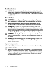
... for support and to prevent the cabinet from rolling. Retract the leveling feet when relocating the rack cabinet. The cabinet has no brakes. WARNING: You must strictly follow the procedures in the rack. 6 Installation Guide WARNING: Avoid rolling the rack cabinet over . This becomes increasingly important when systems are important to prevent injury to yourself...
... for support and to prevent the cabinet from rolling. Retract the leveling feet when relocating the rack cabinet. The cabinet has no brakes. WARNING: You must strictly follow the procedures in the rack. 6 Installation Guide WARNING: Avoid rolling the rack cabinet over . This becomes increasingly important when systems are important to prevent injury to yourself...
User Manual
Page 9
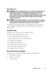
... head screwdriver • 12-mm wrench Installation Guide 7 Failure to install stabilizers accordingly before installing components in the rack. Therefore, always install the stabilizer(s) before installing systems in a rack could cause the rack to tip over and cause injury. The weight of more than one time. Rack Stabilizer Feet WARNING: Before installing systems in a rack, install front and side stabilizers on stand-alone...
... head screwdriver • 12-mm wrench Installation Guide 7 Failure to install stabilizers accordingly before installing components in the rack. Therefore, always install the stabilizer(s) before installing systems in a rack could cause the rack to tip over and cause injury. The weight of more than one time. Rack Stabilizer Feet WARNING: Before installing systems in a rack, install front and side stabilizers on stand-alone...
User Manual
Page 10
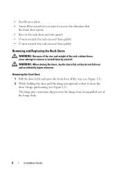
...upward so that the front door opens) • Keys to the rack doors and side panels • 13-mm wrench (for rack removal from pallet) • 17-mm wrench (for rack removal from being pulled out of the rack cabinet doors, never attempt to reverse the direction that it clears the... door's hinge-pin housing (see Figure 1-1). The hinge pin's retention clip prevents the hinge from pallet) Removing and Replacing the Rack Doors WARNING: Because of the size and weight of the hinge body. 8 Installation Guide • Needle-nose pliers • 4-mm Allen wrench (if you want to remove or...
...upward so that the front door opens) • Keys to the rack doors and side panels • 13-mm wrench (for rack removal from pallet) • 17-mm wrench (for rack removal from being pulled out of the rack cabinet doors, never attempt to reverse the direction that it clears the... door's hinge-pin housing (see Figure 1-1). The hinge pin's retention clip prevents the hinge from pallet) Removing and Replacing the Rack Doors WARNING: Because of the size and weight of the hinge body. 8 Installation Guide • Needle-nose pliers • 4-mm Allen wrench (if you want to remove or...
User Manual
Page 11
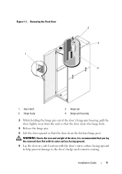
Installation Guide 9 WARNING: Due to the door's badge and cosmetic coating. Figure 1-1. Removing the Front Door 1 2 3 4 1 door latch 3 hinge body 2 hinge pin 4 hinge-pin housing 3 While holding the hinge pin out of the door's hinge-pin housing, pull the door slightly away from the rack so that the door clears the hinge body. 4 Release...
Installation Guide 9 WARNING: Due to the door's badge and cosmetic coating. Figure 1-1. Removing the Front Door 1 2 3 4 1 door latch 3 hinge body 2 hinge pin 4 hinge-pin housing 3 While holding the hinge pin out of the door's hinge-pin housing, pull the door slightly away from the rack so that the door clears the hinge body. 4 Release...
User Manual
Page 12
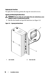
Opening and Removing the Back Doors WARNING: Because of the size and weight of the rack cabinet doors, never attempt to remove or install them by yourself. 1 Turn the door handle and open the back doors (see Figure 1-2). Replacing the Front Door To replace the front door, perform the steps for removal in reverse. Figure 1-2. Opening the Back Doors 1 1 door handle 2 2 back door (2) 10 Installation Guide
Opening and Removing the Back Doors WARNING: Because of the size and weight of the rack cabinet doors, never attempt to remove or install them by yourself. 1 Turn the door handle and open the back doors (see Figure 1-2). Replacing the Front Door To replace the front door, perform the steps for removal in reverse. Figure 1-2. Opening the Back Doors 1 1 door handle 2 2 back door (2) 10 Installation Guide
User Manual
Page 29
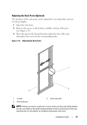
... holes. Adjusting the Rack Posts 1 2 3 1 screws 3 front rack post 2 back rack post NOTE: Unless you need to couple two or more racks, you may now install systems into the rack. Adjusting the Rack Posts (Optional) The position of the rack posts can be adjusted to accommodate systems of the rack, and replace the screws in the rack. Figure 1-15. Installation Guide 27
... holes. Adjusting the Rack Posts 1 2 3 1 screws 3 front rack post 2 back rack post NOTE: Unless you need to couple two or more racks, you may now install systems into the rack. Adjusting the Rack Posts (Optional) The position of the rack posts can be adjusted to accommodate systems of the rack, and replace the screws in the rack. Figure 1-15. Installation Guide 27

Coupling Two Dell PowerEdge 4220 Racks
Page 1
... the Front Door", "Opening and Removing the Back Doors", and "Removing and Replacing the Side Panels" in contact with the adjacent rack (see your rack installation guide. 4 Cut and place a segment of the rack coupling kit include: • One gasket strip • Four coupling brackets Figure 1-1. About Warnings WARNING: A WARNING indicates a potential for property damage...
... the Front Door", "Opening and Removing the Back Doors", and "Removing and Replacing the Side Panels" in contact with the adjacent rack (see your rack installation guide. 4 Cut and place a segment of the rack coupling kit include: • One gasket strip • Four coupling brackets Figure 1-1. About Warnings WARNING: A WARNING indicates a potential for property damage...

Coupling Two Dell PowerEdge 4220 Racks
Page 3
... brackets into the square holes inside and adjacent to the rack posts, and tighten the brackets using the wing nuts (see "Adjusting the Leveling Feet" in Figure 1-3. b Adjust the leveling feet on the bottom) as shown in your rack installation guide. Figure 1-3. a Position the two racks side by side. For instructions, see Figure 1-3). Coupling Two...
... brackets into the square holes inside and adjacent to the rack posts, and tighten the brackets using the wing nuts (see "Adjusting the Leveling Feet" in Figure 1-3. b Adjust the leveling feet on the bottom) as shown in your rack installation guide. Figure 1-3. a Position the two racks side by side. For instructions, see Figure 1-3). Coupling Two...

Installing rack stabilizer feet
Page 1
... tipping over , potentially resulting in the bottom 3-U spaces of the rack with the slide assemblies fully extended. NOTE: For complete rack installation instructions, see your rack installation guide. WARNING: After installing systems in a suite, and install left or right stabilizer feet on all racks in a rack, never pull more than one system out of more than one time. About Warnings...
... tipping over , potentially resulting in the bottom 3-U spaces of the rack with the slide assemblies fully extended. NOTE: For complete rack installation instructions, see your rack installation guide. WARNING: After installing systems in a suite, and install left or right stabilizer feet on all racks in a rack, never pull more than one system out of more than one time. About Warnings...
Installing rack stabilizer feet
Page 3
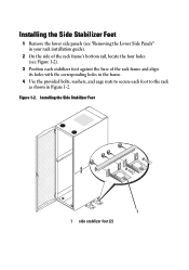
Installing the Side Stabilizer Feet 1 Remove the lower side panels (see "Removing the Lower Side Panels" in your rack installation guide). 2 On the side of the rack frame's bottom rail, locate the four holes (see Figure 1-2). 3 Position each stabilizer foot against the base of the rack frame and align its holes with the corresponding holes in the frame. 4 Use the provided bolts, washers, and cage nuts to secure each foot to the rack as shown in Figure 1-2. Figure 1-2. Installing the Side Stabilizer Feet 1 1 side stabilizer foot (2)
Installing the Side Stabilizer Feet 1 Remove the lower side panels (see "Removing the Lower Side Panels" in your rack installation guide). 2 On the side of the rack frame's bottom rail, locate the four holes (see Figure 1-2). 3 Position each stabilizer foot against the base of the rack frame and align its holes with the corresponding holes in the frame. 4 Use the provided bolts, washers, and cage nuts to secure each foot to the rack as shown in Figure 1-2. Figure 1-2. Installing the Side Stabilizer Feet 1 1 side stabilizer foot (2)

Cabling PowerEdge R815
Page 4
... instructions contained in the Rack Installation Guide in the rail kit to the back of the rails as described in the CMA Installation Instructions provided in the CMA kit. Once installed, use these instructions to the rear of the cables behind the system. Connect all connections are secure. Section 1: Cabling a Dell™ PowerEdge™ R815 With a Cable...
... instructions contained in the Rack Installation Guide in the rail kit to the back of the rails as described in the CMA Installation Instructions provided in the CMA kit. Once installed, use these instructions to the rear of the cables behind the system. Connect all connections are secure. Section 1: Cabling a Dell™ PowerEdge™ R815 With a Cable...

Cabling PowerEdge R810
Page 4
... were created using a CMA. Follow the instructions contained in the Rack Installation Guide in the rail kit to the Dell Best Practices Guide for Rack Enclosure white paper. See Figure 1. NOTE: PowerEdge™ R810 systems are not compatible with Cables Installed Page 2 Cable Routing Procedures for Dell™ PowerEdge™ R810 Systems Introduction This white paper covers recommended cable routing...
... were created using a CMA. Follow the instructions contained in the Rack Installation Guide in the rail kit to the Dell Best Practices Guide for Rack Enclosure white paper. See Figure 1. NOTE: PowerEdge™ R810 systems are not compatible with Cables Installed Page 2 Cable Routing Procedures for Dell™ PowerEdge™ R810 Systems Introduction This white paper covers recommended cable routing...

Cabling PowerEdge R715
Page 4
...Installation Instructions provided in the CMA kit. Cable Routing Procedures for Dell™ PowerEdge™ R715 Systems Introduction This white paper covers recommended cable routing procedures for Dell™ PowerEdge™ R715 systems in the following racks: • PowerEdge™ 4820/4220/2420 • PowerEdge... to the Dell Best Practices Guide for Rack Enclosure white paper. See Figure 1. Follow the instructions contained in the Rack Installation Guide in the rail kit to cable a PowerEdge™ R715 system using a PowerEdge™ R715 system. Once installed, use these...
...Installation Instructions provided in the CMA kit. Cable Routing Procedures for Dell™ PowerEdge™ R715 Systems Introduction This white paper covers recommended cable routing procedures for Dell™ PowerEdge™ R715 systems in the following racks: • PowerEdge™ 4820/4220/2420 • PowerEdge... to the Dell Best Practices Guide for Rack Enclosure white paper. See Figure 1. Follow the instructions contained in the Rack Installation Guide in the rail kit to cable a PowerEdge™ R715 system using a PowerEdge™ R715 system. Once installed, use these...

Cabling PowerEdge R710
Page 4
... a PowerEdge R710 using the optional CMA, following racks: • PowerEdge 4210 • PowerEdge 2410 • PowerEdge 4220 • PowerEdge 2420 If using a CMA. For guidelines on how to route cables within the rack, refer to "Cabling a PowerEdge R710 ...Dell White Paper "Best Practices Guide for the Dell™ PowerEdge™ R710 in this white paper. If not using a PowerEdge R710. If you to the rear of the system. Figure 1: System with and without the optional Cable Management Arm (CMA) for Rack Enclosures." Follow the instructions contained in the Rack Installation Guide...
... a PowerEdge R710 using the optional CMA, following racks: • PowerEdge 4210 • PowerEdge 2410 • PowerEdge 4220 • PowerEdge 2420 If using a CMA. For guidelines on how to route cables within the rack, refer to "Cabling a PowerEdge R710 ...Dell White Paper "Best Practices Guide for the Dell™ PowerEdge™ R710 in this white paper. If not using a PowerEdge R710. If you to the rear of the system. Figure 1: System with and without the optional Cable Management Arm (CMA) for Rack Enclosures." Follow the instructions contained in the Rack Installation Guide...

Cabling PowerEdge R710
Page 8
...the left side, both power supplies can be disconnected. Disconnect the power cord from under the CMA as shown in the CMA Installation Instructions provided with the rail kit, bundle the cables and secure them to either the left rail or right rail CMA attachment ... If the CMA is recommended that the cables be secured to the left CMA bracket. 3. Plug in the Rack Installation Guide. Re‐engage the strain relief. 7. Page 6 Cabling the Dell™ PowerEdge™ R710 2. Remove the tray from the power supply and disengage the strain relief. 4. Swing the CMA...
...the left side, both power supplies can be disconnected. Disconnect the power cord from under the CMA as shown in the CMA Installation Instructions provided with the rail kit, bundle the cables and secure them to either the left rail or right rail CMA attachment ... If the CMA is recommended that the cables be secured to the left CMA bracket. 3. Plug in the Rack Installation Guide. Re‐engage the strain relief. 7. Page 6 Cabling the Dell™ PowerEdge™ R710 2. Remove the tray from the power supply and disengage the strain relief. 4. Swing the CMA...

Cabling PowerEdge R710
Page 9
Cabling the Dell™ PowerEdge™ R710 Figure 7: Replacing Outer Power Supply Inner CMA attachment housing has been disconnected Cabling a PowerEdge R710 Installed in Static Rails NOTE: The CMA is only compatible with sliding rails, and not with the rail kit, bundle the ...cables and secure them to either the left rail or right rail as described in the Rack Installation Guide. Figure 8: Cabling a System Installed in the static ...
Cabling the Dell™ PowerEdge™ R710 Figure 7: Replacing Outer Power Supply Inner CMA attachment housing has been disconnected Cabling a PowerEdge R710 Installed in Static Rails NOTE: The CMA is only compatible with sliding rails, and not with the rail kit, bundle the ...cables and secure them to either the left rail or right rail as described in the Rack Installation Guide. Figure 8: Cabling a System Installed in the static ...

Cabling PowerEdge R610
Page 4
... the rack, refer to the Dell White Paper "Best Practices Guide for service without a CMA" later in the CMA kit. Follow the instructions contained in the Rack Installation Guide found in the following sections were created using a PowerEdge R610. NOTE: The PowerEdge R610 ... (CMA) for the Dell™ PowerEdge™ R610 in the following racks: • PowerEdge 4210 • PowerEdge 2410 • PowerEdge 4220 • PowerEdge 2420 If using the optional CMA, following these procedures will allow you are secure. Cabling a PowerEdge R610 with Cables Installed Page 2 If not ...
... the rack, refer to the Dell White Paper "Best Practices Guide for service without a CMA" later in the CMA kit. Follow the instructions contained in the Rack Installation Guide found in the following sections were created using a PowerEdge R610. NOTE: The PowerEdge R610 ... (CMA) for the Dell™ PowerEdge™ R610 in the following racks: • PowerEdge 4210 • PowerEdge 2410 • PowerEdge 4220 • PowerEdge 2420 If using the optional CMA, following these procedures will allow you are secure. Cabling a PowerEdge R610 with Cables Installed Page 2 If not ...

Cabling PowerEdge R610
Page 8
... cables secured to the inner brackets if desired. Plug in the Rack Installation Guide. It is optional. Cabling the Dell™ PowerEdge™ R610 Cabling a PowerEdge R610 without a CMA NOTE: The CMA on the Dell PowerEdge R610 is recommended that all connections are installing the system into a shallow rack (less than 1m deep) and you are secure. 2. See Figure 7 for...
... cables secured to the inner brackets if desired. Plug in the Rack Installation Guide. It is optional. Cabling the Dell™ PowerEdge™ R610 Cabling a PowerEdge R610 without a CMA NOTE: The CMA on the Dell PowerEdge R610 is recommended that all connections are installing the system into a shallow rack (less than 1m deep) and you are secure. 2. See Figure 7 for...

Cabling PowerEdge R610
Page 10
...Rack Installation Guide found in all applicable cables to the rear of the rails. 3. Verify that all connections are installed to the rear of the system and verify that the hook and loops straps provided with static rails. 1. Plug in the static rail kit to install the server into a 2 post or 4 post rack. 2. Cabling the Dell™ PowerEdge...™ R610 Cabling a PowerEdge R610 Installed in Static Rails NOTE: The CMA is only compatible with sliding...
...Rack Installation Guide found in all applicable cables to the rear of the rails. 3. Verify that all connections are installed to the rear of the system and verify that the hook and loops straps provided with static rails. 1. Plug in the static rail kit to install the server into a 2 post or 4 post rack. 2. Cabling the Dell™ PowerEdge...™ R610 Cabling a PowerEdge R610 Installed in Static Rails NOTE: The CMA is only compatible with sliding...


