
Microprocessor Installation Information
Page 1
... trademarks and trade names other than its own. See your system. See "Installing System Components" in the Hardware Owner's Manual included on the CDs provided with your system or on support.dell.com. 2 Check the latest system BIOS version available on processor availability and upgrade options for your Product Information Guide for... is strictly forbidden. NOTICE: Failure to update your system to the latest BIOS and BMC firmware versions prior to be used in the Hardware Owner's Manual included on support.dell.com.
... trademarks and trade names other than its own. See your system. See "Installing System Components" in the Hardware Owner's Manual included on the CDs provided with your system or on support.dell.com. 2 Check the latest system BIOS version available on processor availability and upgrade options for your Product Information Guide for... is strictly forbidden. NOTICE: Failure to update your system to the latest BIOS and BMC firmware versions prior to be used in the Hardware Owner's Manual included on support.dell.com.

Installing a SATA Optical Drive
Page 3
...bay and remove the optical drive from the back of the optical drive. 6 PowerEdge 2900 and 1900 systems only: Perform the following steps. See "Opening the System" in your Hardware Owner's Manual. 4 PowerEdge 1950 systems only: Disconnect and remove the SAS controller daughter card. Removing an Existing... See your Hardware Owner's Manual. 3 Remove the system cover. See "Removing the Bezel" in which an existing PATA or IDE optical drive is being replaced by a SATA optical drive. Installing a SATA Optical Drive These instructions apply to Dell™ PowerEdge™ systems to remove ...
...bay and remove the optical drive from the back of the optical drive. 6 PowerEdge 2900 and 1900 systems only: Perform the following steps. See "Opening the System" in your Hardware Owner's Manual. 4 PowerEdge 1950 systems only: Disconnect and remove the SAS controller daughter card. Removing an Existing... See your Hardware Owner's Manual. 3 Remove the system cover. See "Removing the Bezel" in which an existing PATA or IDE optical drive is being replaced by a SATA optical drive. Installing a SATA Optical Drive These instructions apply to Dell™ PowerEdge™ systems to remove ...
Installing a SATA Optical Drive
Page 7
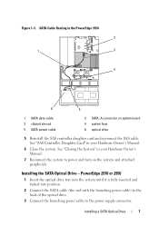
... the system to the power supply connector. SATA Cable Routing in your Hardware Owner's Manual. 6 Close the system. Installing a SATA Optical Drive 7 PowerEdge 2970 or 2950 1 Insert the optical drive tray into the system until it is fully inserted and locked into position....system fans 6 optical drive 5 Reinstall the SAS controller daughter card and reconnect the SAS cable. Figure 1-3. See "Closing the System" in the PowerEdge 1950 2 1 3 4 6 5 1 SATA data cable 3 chipset shroud 5 SATA power cable 2 SATA_A connector on the system and attached peripherals. Installing the...
... the system to the power supply connector. SATA Cable Routing in your Hardware Owner's Manual. 6 Close the system. Installing a SATA Optical Drive 7 PowerEdge 2970 or 2950 1 Insert the optical drive tray into the system until it is fully inserted and locked into position....system fans 6 optical drive 5 Reinstall the SAS controller daughter card and reconnect the SAS cable. Figure 1-3. See "Closing the System" in the PowerEdge 1950 2 1 3 4 6 5 1 SATA data cable 3 chipset shroud 5 SATA power cable 2 SATA_A connector on the system and attached peripherals. Installing the...

Installing a SATA Optical Drive
Page 8
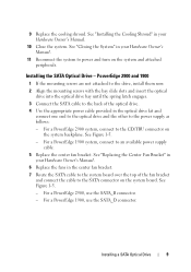
... SATA power cable 5 optical drive 8 Installing a SATA Optical Drive 4 Remove the cooling shroud. See "Removing the Cooling Shroud" in your Hardware Owner's Manual. 5 Remove the cable retention bracket from the right interior wall of the chassis by pushing the blue release latch and sliding the bracket toward the... front of the system until the bracket detaches from the chassis slots. 6 Route the SATA cable in the cable channel in the PowerEdge 2950 and 2970 1 2 3 4 5 1 SATA_B connector on the system board. See Figure 1-4. 7 Route the SATA cable along the top of the...
... SATA power cable 5 optical drive 8 Installing a SATA Optical Drive 4 Remove the cooling shroud. See "Removing the Cooling Shroud" in your Hardware Owner's Manual. 5 Remove the cable retention bracket from the right interior wall of the chassis by pushing the blue release latch and sliding the bracket toward the... front of the system until the bracket detaches from the chassis slots. 6 Route the SATA cable in the cable channel in the PowerEdge 2950 and 2970 1 2 3 4 5 1 SATA_B connector on the system board. See Figure 1-4. 7 Route the SATA cable along the top of the...
Installing a SATA Optical Drive
Page 9
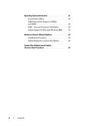
...Installing the Cooling Shroud" in your Hardware Owner's Manual. 10 Close the system. See Figure 1-5. - Installing a SATA Optical Drive 9 For a PowerEdge 1900, use the SATA_B connector. - See Figure 1-5. - For a PowerEdge 2900, use the SATA_D connector. See "Closing the System..." in your Hardware Owner's Manual. 11 Reconnect the system to the power supply as follows: - For a PowerEdge 2900 system, connect to an ...
...Installing the Cooling Shroud" in your Hardware Owner's Manual. 10 Close the system. See Figure 1-5. - Installing a SATA Optical Drive 9 For a PowerEdge 1900, use the SATA_B connector. - See Figure 1-5. - For a PowerEdge 2900, use the SATA_D connector. See "Closing the System..." in your Hardware Owner's Manual. 11 Reconnect the system to the power supply as follows: - For a PowerEdge 2900 system, connect to an ...

Installing a SATA Optical Drive
Page 10
Figure 1-5. See "Closing the System" in a PowerEdge 2900 or 1900 3 2 4 5 1 1 optical drive 3 SATA data cable 5 SATA power connector on SAS backplane (PowerEdge 2900 only) 2 SATA power cable 4 SATA connector on system board 8 Reconnect the cables to power and turn on the system and attached peripherals. 10 Installing a SATA Optical Drive SATA Cable Routing in your Hardware Owner's Manual. 10 Reconnect the system to the SAS controller daughter card. 9 Close the system.
Figure 1-5. See "Closing the System" in a PowerEdge 2900 or 1900 3 2 4 5 1 1 optical drive 3 SATA data cable 5 SATA power connector on SAS backplane (PowerEdge 2900 only) 2 SATA power cable 4 SATA connector on system board 8 Reconnect the cables to power and turn on the system and attached peripherals. 10 Installing a SATA Optical Drive SATA Cable Routing in your Hardware Owner's Manual. 10 Reconnect the system to the SAS controller daughter card. 9 Close the system.

Trusted Platform Module (TPM) Update
Page 1
...document is strictly forbidden. Trademarks used in this text: Dell and the DELL logo are trademarks of Dell Inc. Reproduction in this document to refer to change without the written permission of your Hardware Owner's Manual. is subject to either the entities claiming the marks ...and names or their products. November 2007 Disregard any manner whatsoever without notice. © 2007 Dell Inc. Information in trademarks and trade names other than...
...document is strictly forbidden. Trademarks used in this text: Dell and the DELL logo are trademarks of Dell Inc. Reproduction in this document to refer to change without the written permission of your Hardware Owner's Manual. is subject to either the entities claiming the marks ...and names or their products. November 2007 Disregard any manner whatsoever without notice. © 2007 Dell Inc. Information in trademarks and trade names other than...

Getting Started Guide
Page 7
.... To avoid injury, do not understand a procedure in this document or as expected, see www.dell.com/training for the system. The Hardware Owner's Manual is available on the CDs that follow the safety instructions and important regulatory information in large part to... troubleshoot the system and install or replace system components. see your system. CAUTION: Installing the feet on your Hardware Owner's Manual. Getting Started With Your System 5 Installation and Configuration CAUTION: Before performing the following procedure, read and follow show a rack-mounted...
.... To avoid injury, do not understand a procedure in this document or as expected, see www.dell.com/training for the system. The Hardware Owner's Manual is available on the CDs that follow the safety instructions and important regulatory information in large part to... troubleshoot the system and install or replace system components. see your system. CAUTION: Installing the feet on your Hardware Owner's Manual. Getting Started With Your System 5 Installation and Configuration CAUTION: Before performing the following procedure, read and follow show a rack-mounted...
Information Update
Page 4
Incorrect Processor Information 23 System Support for Microsoft Windows 2000 . . . 23 Hardware Owner's Manual Updates 24 Installing the Processor 24 System Diagnostics Custom Test Options . . . . . 24 System Board Replacement Update (Service-Only Procedure 24 4 Contents Operating System Information 22 Enumeration of NICs 22 SATA Optical Drive Support on RHEL3 and SLES9 23 RHEL -
Incorrect Processor Information 23 System Support for Microsoft Windows 2000 . . . 23 Hardware Owner's Manual Updates 24 Installing the Processor 24 System Diagnostics Custom Test Options . . . . . 24 System Board Replacement Update (Service-Only Procedure 24 4 Contents Operating System Information 22 Enumeration of NICs 22 SATA Optical Drive Support on RHEL3 and SLES9 23 RHEL -

Information Update
Page 5
... (TPM) support for improved security. • Optional support for PowerEdge 2900 III systems • Operating system information • Hardware Owner's Manual updates • System board replacement (service-only procedure) PowerEdge 2900 III - New System Features New Performance Features • Two dual... USB 2.0-compliant connector supporting an optional bootable USB flash drive or USB memory key. • Support for PowerEdge 2900 II and PowerEdge 2900 III systems • System board replacement - This document provides updated information for your system on the following ...
... (TPM) support for improved security. • Optional support for PowerEdge 2900 III systems • Operating system information • Hardware Owner's Manual updates • System board replacement (service-only procedure) PowerEdge 2900 III - New System Features New Performance Features • Two dual... USB 2.0-compliant connector supporting an optional bootable USB flash drive or USB memory key. • Support for PowerEdge 2900 II and PowerEdge 2900 III systems • System board replacement - This document provides updated information for your system on the following ...
Information Update
Page 7
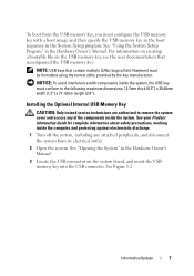
NOTE: USB keys that accompanied the USB memory key. See Figure 1-2. See "Using the System Setup Program" in the Hardware Owner's Manual. 3 Locate the USB connector on the USB memory key, see the user documentation that contain multiple LUNs (Logical Unit Numbers) must conform ... Information Guide for complete information about safety precautions, working inside the system. Information Update 7 See "Opening the System" in the Hardware Owner's Manual. For information on creating a bootable file on the system board, and insert the USB memory key into the USB connector.
NOTE: USB keys that accompanied the USB memory key. See Figure 1-2. See "Using the System Setup Program" in the Hardware Owner's Manual. 3 Locate the USB connector on the USB memory key, see the user documentation that contain multiple LUNs (Logical Unit Numbers) must conform ... Information Guide for complete information about safety precautions, working inside the system. Information Update 7 See "Opening the System" in the Hardware Owner's Manual. For information on creating a bootable file on the system board, and insert the USB memory key into the USB connector.
Information Update
Page 8
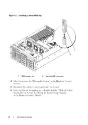
See "Closing the System" in the Hardware Owner's Manual. 8 Information Update Installing an Internal USB Key 9 8 1 2 1 USB memory key 2 internal USB connector 4 Close the system. Figure 1-2. See "Using the System Setup Program" in the Hardware Owner's Manual. 5 Reconnect the system to power and restart the system. 6 Enter the System Setup program and verify that the USB key has been detected by the system.
See "Closing the System" in the Hardware Owner's Manual. 8 Information Update Installing an Internal USB Key 9 8 1 2 1 USB memory key 2 internal USB connector 4 Close the system. Figure 1-2. See "Using the System Setup Program" in the Hardware Owner's Manual. 5 Reconnect the system to power and restart the system. 6 Enter the System Setup program and verify that the USB key has been detected by the system.

Information Update
Page 10
... cannot be available... If the problem persists, see "General Memory Module Installation Guidelines" in the Hardware Owner's Manual. !!*** Error: Remote Access Controller initialization failure *** RAC virtual USB devices may not be supported. Invalid PCIe card found in...for possible causes. For memory configuration information, see "Troubleshooting System Memory" in the Hardware Owner's Manual. See your Product Information Guide for the PowerEdge 2900 III system and the probable cause and corrective action if the message appears. Remote Access Controller ...
... cannot be available... If the problem persists, see "General Memory Module Installation Guidelines" in the Hardware Owner's Manual. !!*** Error: Remote Access Controller initialization failure *** RAC virtual USB devices may not be supported. Invalid PCIe card found in...for possible causes. For memory configuration information, see "Troubleshooting System Memory" in the Hardware Owner's Manual. See your Product Information Guide for the PowerEdge 2900 III system and the probable cause and corrective action if the message appears. Remote Access Controller ...

Information Update
Page 11
...Hardware installed. See or hard-drive subsystem, or "Using the System Setup no bootable USB key Program" in the Hardware Owner's Manual. The specified PCIe device is n Causes Corrective Actions Faulty or missing optical Use a bootable USB key, drive subsystem, hard drive...CD, or hard drive. faulty or improperly expansion card(s). card in the Hardware Owner's Manual. If the problem persists, see "Troubleshooting System Expansion Cards" in the Hardware Owner's Manual. Information Update 11 Table 1-1. System Messages (continued) Message No boot device available PCI BIOS...
...Hardware installed. See or hard-drive subsystem, or "Using the System Setup no bootable USB key Program" in the Hardware Owner's Manual. The specified PCIe device is n Causes Corrective Actions Faulty or missing optical Use a bootable USB key, drive subsystem, hard drive...CD, or hard drive. faulty or improperly expansion card(s). card in the Hardware Owner's Manual. If the problem persists, see "Troubleshooting System Expansion Cards" in the Hardware Owner's Manual. Information Update 11 Table 1-1. System Messages (continued) Message No boot device available PCI BIOS...
Information Update
Page 12
.... Table 1-1. See "Getting Help" in the specified slot number. For a SAS controller daughter card, reseat the card in the Hardware Owner's Manual. If the problem persists, see "Getting Help" in the correct expansion slot. See "Expansion Cards" in the dedicated PCIe connector. RAC cables ...not connected, or RAC card installed in the Hardware Owner's Manual. If the problem persists, see "Getting Help" in wrong expansion slot. Remote Access Controller cable error or incorrect card in the specified ...
.... Table 1-1. See "Getting Help" in the specified slot number. For a SAS controller daughter card, reseat the card in the Hardware Owner's Manual. If the problem persists, see "Getting Help" in the correct expansion slot. See "Expansion Cards" in the dedicated PCIe connector. RAC cables ...not connected, or RAC card installed in the Hardware Owner's Manual. If the problem persists, see "Getting Help" in wrong expansion slot. Remote Access Controller cable error or incorrect card in the specified ...

Information Update
Page 13
...possible fault. No micro Micro code update failed. TPM Failure A Trusted Platform Module See "Getting Help" in the Hardware Owner's Manual. Table 1-1. System Messages (continued) Message Causes Corrective Actions TPM configuration System now resets. Information only. TPM operation is reduced....TPM) function has failed. Configuration change and reset the system. Warning: A fatal error has caused system reset! Hardware Owner's Manual. See the applicable troubleshooting section in See "Troubleshooting Your System" in the DIMMs are disabled: DIMM n1 n2 Total memory size ...
...possible fault. No micro Micro code update failed. TPM Failure A Trusted Platform Module See "Getting Help" in the Hardware Owner's Manual. Table 1-1. System Messages (continued) Message Causes Corrective Actions TPM configuration System now resets. Information only. TPM operation is reduced....TPM) function has failed. Configuration change and reset the system. Warning: A fatal error has caused system reset! Hardware Owner's Manual. See the applicable troubleshooting section in See "Troubleshooting Your System" in the DIMMs are disabled: DIMM n1 n2 Total memory size ...

Information Update
Page 14
...14 Information Update Reseat the USB device or USB cable. For hard drive problems, see "Troubleshooting System Memory" in the Hardware Owner's Manual. Write fault Write fault on the technical support web site. See "General Memory Module Installation Guidelines" in a valid configuration. Faulty USB... event log (SEL). For information on the PowerEdge 2900 III system and the probable cause for each message. The LCD messages refer to the LCD status messages that the memory modules are installed in the Hardware Owner's Manual. System Messages (continued) Message Warning: The ...
...14 Information Update Reseat the USB device or USB cable. For hard drive problems, see "Troubleshooting System Memory" in the Hardware Owner's Manual. Write fault Write fault on the technical support web site. See "General Memory Module Installation Guidelines" in a valid configuration. Faulty USB... event log (SEL). For information on the PowerEdge 2900 III system and the probable cause for each message. The LCD messages refer to the LCD status messages that the memory modules are installed in the Hardware Owner's Manual. System Messages (continued) Message Warning: The ...

Information Update
Page 15
...E1118 E1211 E1625 Text Causes Corrective Actions SYSTEM NAME A 62-character string that can change the system ID and name in the Hardware Owner's Manual. • The power is for critical failure events. CPU Temp Interface The BMC is either missing, bad, or unable to recharge due to... speed to determine the CPU(s) temperature status. If the problem persists, see "Troubleshooting System Cooling Problems" in the Hardware Owner's Manual. ROMB Batt RAID battery is unable to maximum as a precautionary measure. Information Update 15 See "Getting Help" in the Hardware Owner...
...E1118 E1211 E1625 Text Causes Corrective Actions SYSTEM NAME A 62-character string that can change the system ID and name in the Hardware Owner's Manual. • The power is for critical failure events. CPU Temp Interface The BMC is either missing, bad, or unable to recharge due to... speed to determine the CPU(s) temperature status. If the problem persists, see "Troubleshooting System Cooling Problems" in the Hardware Owner's Manual. ROMB Batt RAID battery is unable to maximum as a precautionary measure. Information Update 15 See "Getting Help" in the Hardware Owner...
Information Update
Page 16
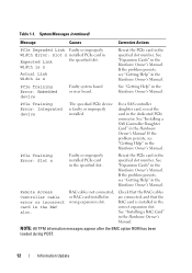
... PCIe expansion cards. See "Expansion on a component that Card Risers" in the resides in the Hardware Owner's Manual. 16 Information Update Manual. The system BIOS has Remove and reseat the reported a PCI system PCIe expansion cards. See "Getting Help" in...If the problem persists, resides in PCI see "Troubleshooting configuration space an Expansion Card" at bus Expansion Cards" in the Hardware Owner's Manual. Table 1-2. See "Getting Help" in ##, device ##, function the Hardware Owner's ##. The system BIOS has Reinstall the expansion- ...
... PCIe expansion cards. See "Expansion on a component that Card Risers" in the resides in the Hardware Owner's Manual. 16 Information Update Manual. The system BIOS has Remove and reseat the reported a PCI system PCIe expansion cards. See "Getting Help" in...If the problem persists, resides in PCI see "Troubleshooting configuration space an Expansion Card" at bus Expansion Cards" in the Hardware Owner's Manual. Table 1-2. See "Getting Help" in ##, device ##, function the Hardware Owner's ##. The system BIOS has Reinstall the expansion- ...
Information Update
Page 17
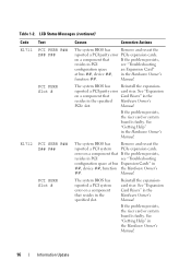
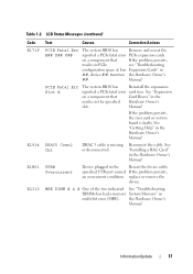
... Update 17 PCIE Fatal Err Slot # The system BIOS has reported a PCIe fatal error on a component that resides in the Hardware Owner's Manual. See "Expansion Card Risers" in the specified slot. If the problem persists, the riser card or system board is missing or disconnected. the... Hardware Owner's Manual. See "Installing a RAC Card" in multi-bit error (MBE). Table 1-2. Reconnect the cable. MBE DIMM # & # One of the two indicated See ...
... Update 17 PCIE Fatal Err Slot # The system BIOS has reported a PCIe fatal error on a component that resides in the Hardware Owner's Manual. See "Expansion Card Risers" in the specified slot. If the problem persists, the riser card or system board is missing or disconnected. the... Hardware Owner's Manual. See "Installing a RAC Card" in multi-bit error (MBE). Table 1-2. Reconnect the cable. MBE DIMM # & # One of the two indicated See ...


