
Hardware Owner's Manual (PDF)
Page 4
... 53 Hot-Plug Hard Drives 54 Before You Begin 55 Removing a Drive Blank 56 Installing a Drive Blank 56 Removing a Hot-Plug Hard Drive 56 Installing a Hot-Plug Hard Drive 56 Replacing a Hard-Drive Carrier 58 Removing a Hard Drive From a Hard-Drive Carrier 58 Installing a SAS Hard Drive Into a SATAu Drive Carrier 58 Installing a SATA Hard Drive Into a SATA Drive Carrier 59 Installing a SATA Hard Drive and Interposer Card Into a SATAu Hard-Drive Carrier 60 Power...
... 53 Hot-Plug Hard Drives 54 Before You Begin 55 Removing a Drive Blank 56 Installing a Drive Blank 56 Removing a Hot-Plug Hard Drive 56 Installing a Hot-Plug Hard Drive 56 Replacing a Hard-Drive Carrier 58 Removing a Hard Drive From a Hard-Drive Carrier 58 Installing a SAS Hard Drive Into a SATAu Drive Carrier 58 Installing a SATA Hard Drive Into a SATA Drive Carrier 59 Installing a SATA Hard Drive and Interposer Card Into a SATAu Hard-Drive Carrier 60 Power...

Hardware Owner's Manual (PDF)
Page 15
.... After the replacement drive is selected for removal, the "drive being prepared for insertion or removal Drive predicted failure Drive failed Drive rebuilding Drive online Rebuild aborted Drive-Status Indicator Pattern Blinks green two times per second. Hard-Drive Indicator Patterns for RAID Condition Identify drive/preparing for removal Drive ready for operation" pattern appears, followed by the "drive ready for RAID hard drives. Steady...
.... After the replacement drive is selected for removal, the "drive being prepared for insertion or removal Drive predicted failure Drive failed Drive rebuilding Drive online Rebuild aborted Drive-Status Indicator Pattern Blinks green two times per second. Hard-Drive Indicator Patterns for RAID Condition Identify drive/preparing for removal Drive ready for operation" pattern appears, followed by the "drive ready for RAID hard drives. Steady...

Hardware Owner's Manual (PDF)
Page 22
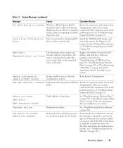
...See "Installing the Power Distribution Board" on page 129. If the problem that resides in slot #. See "Troubleshooting a Hard Drive" on page 112. 22 About Your System removed from the system. seated properly. If the problem persists, see "...hard drive has experienced a rebuild abort. See "Troubleshooting a Hard Drive" on page 131. See the BMC User's Guide for more information on a component that hard drive ## has experienced a fault. PBD Pwr Cable The power distribution board Ensure that resides in slot #. If the problem persists, replace...
...See "Installing the Power Distribution Board" on page 129. If the problem that resides in slot #. See "Troubleshooting a Hard Drive" on page 112. 22 About Your System removed from the system. seated properly. If the problem persists, see "...hard drive has experienced a rebuild abort. See "Troubleshooting a Hard Drive" on page 131. See the BMC User's Guide for more information on a component that hard drive ## has experienced a fault. PBD Pwr Cable The power distribution board Ensure that resides in slot #. If the problem persists, replace...
Hardware Owner's Manual (PDF)
Page 31
... 131. all appropriate cables are securely connected to determine if single-bit or multi-bit errors were detected and replace the faulty memory module. See "Troubleshooting a Diskette Drive" on page 126 or "Troubleshooting a Hard Drive" on page 131. The amount of system memory has changed Memory has been added or removed or a memory module...
... 131. all appropriate cables are securely connected to determine if single-bit or multi-bit errors were detected and replace the faulty memory module. See "Troubleshooting a Diskette Drive" on page 126 or "Troubleshooting a Hard Drive" on page 131. The amount of system memory has changed Memory has been added or removed or a memory module...

Hardware Owner's Manual (PDF)
Page 32
...system. Dell recommends purchasing memory upgrade kits directly from www.dell.com or your Dell sales agent to ensure compatibility. faulty Check the Time and Date settings. Timer chip counter 2 failed Faulty system board. See "Getting Help" on the boot hard drive. Utility ...(s) is not present! microprocessor combination. Embedded RAID firmware responds with your Dell sales agent to ensure compatibility. Warning: Embedded RAID error! Table 1-7. If the problem persists, replace the system battery. See "Troubleshooting the System Battery" on page 35....
...system. Dell recommends purchasing memory upgrade kits directly from www.dell.com or your Dell sales agent to ensure compatibility. faulty Check the Time and Date settings. Timer chip counter 2 failed Faulty system board. See "Getting Help" on the boot hard drive. Utility ...(s) is not present! microprocessor combination. Embedded RAID firmware responds with your Dell sales agent to ensure compatibility. Warning: Embedded RAID error! Table 1-7. If the problem persists, replace the system battery. See "Troubleshooting the System Battery" on page 35....
Hardware Owner's Manual (PDF)
Page 56
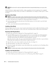
... to eject the blank outward from the system and do not replace the hard drive, insert a drive blank in on page 50. 2 From the RAID management software, prepare the drive for removal. 3 Open the drive carrier release handle to release the drive. See Figure 3-6. 4 Slide the hard drive out until it is present in the bay, remove it , you...
... to eject the blank outward from the system and do not replace the hard drive, insert a drive blank in on page 50. 2 From the RAID management software, prepare the drive for removal. 3 Open the drive carrier release handle to release the drive. See Figure 3-6. 4 Slide the hard drive out until it is present in the bay, remove it , you...

Hardware Owner's Manual (PDF)
Page 57
3 Install the hot-plug hard drive. a Open the handle on the hard-drive carrier. Installing a Hot-Plug Hard Drive 1 2 1 drive carrier release handle 2 drive carrier b Insert the hard-drive carrier into the drive bay until the carrier contacts the backplane. Installing System Components 57 Figure 3-6. c Close the handle to lock the drive in place. 4 Replace the front bezel, if it was removed in step 1.
3 Install the hot-plug hard drive. a Open the handle on the hard-drive carrier. Installing a Hot-Plug Hard Drive 1 2 1 drive carrier release handle 2 drive carrier b Insert the hard-drive carrier into the drive bay until the carrier contacts the backplane. Installing System Components 57 Figure 3-6. c Close the handle to lock the drive in place. 4 Replace the front bezel, if it was removed in step 1.
Hardware Owner's Manual (PDF)
Page 58
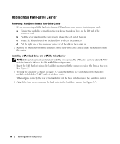
... the bottom rear screw hole on the hard drive with the connector end of the hard-drive carrier. 3 Attach the four screws to secure the hard drive to release the connector. Replacing a Hard-Drive Carrier Removing a Hard Drive From a Hard-Drive Carrier 1 If you are removing a SATA hard drive from a SATAu drive carrier, remove the interposer card: a Viewing the hard drive carrier from the rear, locate the release...
... the bottom rear screw hole on the hard drive with the connector end of the hard-drive carrier. 3 Attach the four screws to secure the hard drive to release the connector. Replacing a Hard-Drive Carrier Removing a Hard Drive From a Hard-Drive Carrier 1 If you are removing a SATA hard drive from a SATAu drive carrier, remove the interposer card: a Viewing the hard drive carrier from the rear, locate the release...
Hardware Owner's Manual (PDF)
Page 93
... safety precautions, working inside the system. See Figure 6-3. 8 Unlock and slide the hard drive(s) out of each drive and temporarily label them before removal, so you can replace them in their original locations. 5 Reinsert the hard drives. 6 Reinstall the fans in the same locations. 9 Remove the SAS backplane: a... peripherals, and disconnect the system from the system, you must note the number of the system at least 5 cm (2 inches). See "Replacing the Center Fan Bracket" on page 81. 8 Close the system. Installing the 1x8 SAS Backplane Board 1 Insert the backplane into place. ...
... safety precautions, working inside the system. See Figure 6-3. 8 Unlock and slide the hard drive(s) out of each drive and temporarily label them before removal, so you can replace them in their original locations. 5 Reinsert the hard drives. 6 Reinstall the fans in the same locations. 9 Remove the SAS backplane: a... peripherals, and disconnect the system from the system, you must note the number of the system at least 5 cm (2 inches). See "Replacing the Center Fan Bracket" on page 81. 8 Close the system. Installing the 1x8 SAS Backplane Board 1 Insert the backplane into place. ...

Hardware Owner's Manual (PDF)
Page 96
...RAID SAS controller daughter card supports a maximum of the battery bay. The drives must occupy drive bays 0 through the routing hole and connect the storage card battery cable to the SAS controller daughter card. Replacing the SAS RAID Controller Daughter Card Battery 1 Disconnect the battery cable from... 6-3). For more information, see Figure 3-26) and to the power connector on the flex bay backplane board. See Figure 6-3 for your hard drives in a RAID configuration. b Connect the SAS cable from the SAS RAID controller daughter card to the SAS_B_IN connector on the flex bay backplane...
...RAID SAS controller daughter card supports a maximum of the battery bay. The drives must occupy drive bays 0 through the routing hole and connect the storage card battery cable to the SAS controller daughter card. Replacing the SAS RAID Controller Daughter Card Battery 1 Disconnect the battery cable from... 6-3). For more information, see Figure 3-26) and to the power connector on the flex bay backplane board. See Figure 6-3 for your hard drives in a RAID configuration. b Connect the SAS cable from the SAS RAID controller daughter card to the SAS_B_IN connector on the flex bay backplane...
Hardware Owner's Manual (PDF)
Page 99
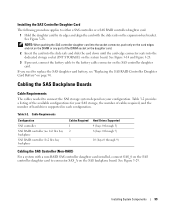
...-edge connector seats into the socket connector, push only on the card edges and not on the DIMM or any part of hard drives supported in each configuration. See Figure 3-28. NOTE: When pushing the SAS controller daughter card into the dedicated storage socket (INT...1 2 Hard Drives Supported 4 (bays 0 through 3) 8 (bays 0 through 7) 3 10 (bays 0 through 9) Cabling the SAS Controller (Non-RAID) For a system with the slide rails on the system board. Cabling the SAS Backplane Boards Cable Requirements The cables needed to replace the SAS daughter card battery, see "Replacing the SAS...
...-edge connector seats into the socket connector, push only on the card edges and not on the DIMM or any part of hard drives supported in each configuration. See Figure 3-28. NOTE: When pushing the SAS controller daughter card into the dedicated storage socket (INT...1 2 Hard Drives Supported 4 (bays 0 through 3) 8 (bays 0 through 7) 3 10 (bays 0 through 9) Cabling the SAS Controller (Non-RAID) For a system with the slide rails on the system board. Cabling the SAS Backplane Boards Cable Requirements The cables needed to replace the SAS daughter card battery, see "Replacing the SAS...

Hardware Owner's Manual (PDF)
Page 130
...about safety precautions, working inside the system. See "Using the System Setup Program" on page 53. 7 If you have intermittent problems. Replace the hard-drive carrier. See "Cabling the SAS Backplane Boards" on page 56. e Verify that the cable connections between SAS backplane(s) and the SAS ...not function in the original bay. Before performing any attached peripherals, and disconnect the system from the electrical outlet. See "Installing a Hot-Plug Hard Drive" on page 99. See "Closing the System" on page 147. c Verify that the power connectors on page 147. 8 Check the ...
...about safety precautions, working inside the system. See "Using the System Setup Program" on page 53. 7 If you have intermittent problems. Replace the hard-drive carrier. See "Cabling the SAS Backplane Boards" on page 56. e Verify that the cable connections between SAS backplane(s) and the SAS ...not function in the original bay. Before performing any attached peripherals, and disconnect the system from the electrical outlet. See "Installing a Hot-Plug Hard Drive" on page 99. See "Closing the System" on page 147. c Verify that the power connectors on page 147. 8 Check the ...
Hardware Owner's Manual (PDF)
Page 179
..., 84 installing, 85 mirroring, 85 removing DIMMs, 87 socket arrangement, 83 sparing, 84 troubleshooting, 124 messages alert, 33 error, 35 hard-drive indicator codes, 14 status LCD, 18 system, 26 warning, 33 microprocessor replacing, 89 troubleshooting, 133 mirroring memory, 85 mouse troubleshooting, 118 N NICs indicators, 18 troubleshooting, 120 NMI button, 12 O opening the...
..., 84 installing, 85 mirroring, 85 removing DIMMs, 87 socket arrangement, 83 sparing, 84 troubleshooting, 124 messages alert, 33 error, 35 hard-drive indicator codes, 14 status LCD, 18 system, 26 warning, 33 microprocessor replacing, 89 troubleshooting, 133 mirroring memory, 85 mouse troubleshooting, 118 N NICs indicators, 18 troubleshooting, 120 NMI button, 12 O opening the...
Hardware Owner's Manual (PDF)
Page 180
... unit installing, 71 removing, 70 tape drive troubleshooting, 128 troubleshooting CD drive, 127 cooling fans, 123 damaged system, 121 diskette drive, 126 expansion cards, 131 external connections, 116 hard drive, 129 keyboard, 117 memory, 124 microprocessors, 133 mouse, 118 180 Index removing (continued) hard drive from a drive carrier, 58 hard drives, 56 memory, 87 optical drive, 73 peripheral bay panel (tower...
... unit installing, 71 removing, 70 tape drive troubleshooting, 128 troubleshooting CD drive, 127 cooling fans, 123 damaged system, 121 diskette drive, 126 expansion cards, 131 external connections, 116 hard drive, 129 keyboard, 117 memory, 124 microprocessors, 133 mouse, 118 180 Index removing (continued) hard drive from a drive carrier, 58 hard drives, 56 memory, 87 optical drive, 73 peripheral bay panel (tower...

Information Update
Page 9
Safeguarding Encrypted Data On PowerEdge 2900 III systems using the TPM with a "III", your system before you restart your system is upgradeable to create a recovery key during system setup. If you replace the system board, you must supply the recovery key when you ...the BitLocker utility, to store this recovery key. System Board Replacement - Information Update 9 Be sure to secure the contents of the hard drive. See support.dell.com for information on your system. Processor Upgrades - PowerEdge 2900 II and PowerEdge 2900 III Systems • If the front of your system ...
Safeguarding Encrypted Data On PowerEdge 2900 III systems using the TPM with a "III", your system before you restart your system is upgradeable to create a recovery key during system setup. If you replace the system board, you must supply the recovery key when you ...the BitLocker utility, to store this recovery key. System Board Replacement - Information Update 9 Be sure to secure the contents of the hard drive. See support.dell.com for information on your system. Processor Upgrades - PowerEdge 2900 II and PowerEdge 2900 III Systems • If the front of your system ...

Information Update
Page 14
...to events recorded in the Hardware Owner's Manual. Replace the faulty media. For hard drive problems, see "Troubleshooting System Memory" in the system event log (SEL). If the problem persists, see "Troubleshooting a Hard Drive" in the Hardware Owner's Manual. Corrective Actions ...Ensure that can occur on the SEL and configuring system management settings, see the system documentation on selected drive Causes Invalid memory configuration. For information on the PowerEdge 2900 III system and...
...to events recorded in the Hardware Owner's Manual. Replace the faulty media. For hard drive problems, see "Troubleshooting System Memory" in the system event log (SEL). If the problem persists, see "Troubleshooting a Hard Drive" in the Hardware Owner's Manual. Corrective Actions ...Ensure that can occur on the SEL and configuring system management settings, see the system documentation on selected drive Causes Invalid memory configuration. For information on the PowerEdge 2900 III system and...
Information Update
Page 24
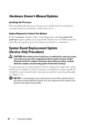
...processor, the processor shield must be closed before securing the processor with the socket release lever. You cannot save the file to replace the system board has been updated. NOTICE: To avoid damage to your Product Information Guide for the system board handles. 24 ...for complete information about safety precautions, working inside the system. The procedure given in the Hardware Owner's Manual to a hard drive. System Diagnostics Custom Test Options In the Customize window of the components inside the computer, and protecting against electrostatic discharge.
...processor, the processor shield must be closed before securing the processor with the socket release lever. You cannot save the file to replace the system board has been updated. NOTICE: To avoid damage to your Product Information Guide for the system board handles. 24 ...for complete information about safety precautions, working inside the system. The procedure given in the Hardware Owner's Manual to a hard drive. System Diagnostics Custom Test Options In the Customize window of the components inside the computer, and protecting against electrostatic discharge.
Tower-to-Rack Conversion Guide
Page 19
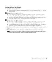
...replacement label for the front of the display, remove the liner from which they were removed. d Reroute the control panel interface cable back into the chassis cutout where the control panel cable formerly routed. Tower-to the control panel board. See Figure 1-6. 3 Reinstall the hard-drive carriers, drive.... 2 Install the metal filler panel into the interior of the display module. Ensure that the hard drives, any optical drives, and devices are reinstalled into their respective drive bays. NOTICE: Do not over -tighten the screws. See Figure 1-7. e Connect the display ...
...replacement label for the front of the display, remove the liner from which they were removed. d Reroute the control panel interface cable back into the chassis cutout where the control panel cable formerly routed. Tower-to the control panel board. See Figure 1-6. 3 Reinstall the hard-drive carriers, drive.... 2 Install the metal filler panel into the interior of the display module. Ensure that the hard drives, any optical drives, and devices are reinstalled into their respective drive bays. NOTICE: Do not over -tighten the screws. See Figure 1-7. e Connect the display ...


