
Service Manual
Page 3
Contents Chapter 1 System Overview 1-1 System Features 1-1 System Memory 1-7 Advanced Expansion Subsystem 1-7 Integrated Server Management 1-8 Video Controller 1-8 Integrated SCSI Controllers 1-8 SCSI Hard-Disk Drives 1-8 SCSI Configuration Guidelines 1-9 SCSI ID Numbers 1-9 Device Termination 1-9 SCSI Cable 1-...
Contents Chapter 1 System Overview 1-1 System Features 1-1 System Memory 1-7 Advanced Expansion Subsystem 1-7 Integrated Server Management 1-8 Video Controller 1-8 Integrated SCSI Controllers 1-8 SCSI Hard-Disk Drives 1-8 SCSI Configuration Guidelines 1-9 SCSI ID Numbers 1-9 Device Termination 1-9 SCSI Cable 1-...

Service Manual
Page 4
... 4-11 Power Supply 4-12 Power-Supply Paralleling Board 4-13 Control Panel 4-14 Cooling Fans 4-15 System Board Components 4-16 Expansion Cards 4-17 Support Panel 4-18 Memory, Microprocessor, and Termination Module 4-19 SIMM 4-20 Microprocessor and Heat Sink 4-22 Real-Time Clock Chip 4-25 vi
... 4-11 Power Supply 4-12 Power-Supply Paralleling Board 4-13 Control Panel 4-14 Cooling Fans 4-15 System Board Components 4-16 Expansion Cards 4-17 Support Panel 4-18 Memory, Microprocessor, and Termination Module 4-19 SIMM 4-20 Microprocessor and Heat Sink 4-22 Real-Time Clock Chip 4-25 vi

Service Manual
Page 5
... Submenu A-7 Advanced Chipset Configuration Submenu A-9 Plug and Play Configuration Submenu A-11 Security Menu A-12 Exit Menu A-14 Index Figures Figure 1-1. Power Supply Connectors 1-11 Figure 1-8. Memory Module and SIMM Sockets 1-7 Figure 1-7. Power Distribution 1-15 Figure 1-14. SCSI Backplane Board 1-21 vii System Board Components 1-16 Figure 1-15. Back Panel Features 1-6 Figure...
... Submenu A-7 Advanced Chipset Configuration Submenu A-9 Plug and Play Configuration Submenu A-11 Security Menu A-12 Exit Menu A-14 Index Figures Figure 1-1. Power Supply Connectors 1-11 Figure 1-8. Memory Module and SIMM Sockets 1-7 Figure 1-7. Power Distribution 1-15 Figure 1-14. SCSI Backplane Board 1-21 vii System Board Components 1-16 Figure 1-15. Back Panel Features 1-6 Figure...

Service Manual
Page 6
... Hard-Disk Drive Removal 4-10 Figure 4-10. Control Panel Removal 4-14 Figure 4-14. System Board Components 4-16 Figure 4-16. Memory Module and SIMM Sockets 4-20 Figure 4-20. System Board Removal 4-27 Figure 4-28. Main Menu A-3 Figure A-2. Advanced Menu A-6...Power-Supply Paralleling Board Removal 4-13 Figure 4-13. Removing a Microprocessor 4-24 Figure 4-25. Front-Panel Insert Removal 4-6 Figure 4-6. Memory, Microprocessor, and Termination Module Removal 4-19 Figure 4-19. Microprocessor Configuration 4-22 Figure 4-23. Security Menu A-12 Figure A-8. Expansion ...
... Hard-Disk Drive Removal 4-10 Figure 4-10. Control Panel Removal 4-14 Figure 4-14. System Board Components 4-16 Figure 4-16. Memory Module and SIMM Sockets 4-20 Figure 4-20. System Board Removal 4-27 Figure 4-28. Main Menu A-3 Figure A-2. Advanced Menu A-6...Power-Supply Paralleling Board Removal 4-13 Figure 4-13. Removing a Microprocessor 4-24 Figure 4-25. Front-Panel Insert Removal 4-6 Figure 4-6. Memory, Microprocessor, and Termination Module Removal 4-19 Figure 4-19. Microprocessor Configuration 4-22 Figure 4-23. Security Menu A-12 Figure A-8. Expansion ...

Service Manual
Page 9
... can have been designed for better serviceability and increased reliability, with 1 MB video memory standard System Overview 1-1 Contact Dell for the Dell PowerEdge 6100/200 system is 200 MHz derived from a system clock frequency of 66 MHz. Chapter 1 System Overview The Dell® PowerEdge® 6100 system covered in this manual is installed) • Optional, redundant hot-pluggable...
... can have been designed for better serviceability and increased reliability, with 1 MB video memory standard System Overview 1-1 Contact Dell for the Dell PowerEdge 6100/200 system is 200 MHz derived from a system clock frequency of 66 MHz. Chapter 1 System Overview The Dell® PowerEdge® 6100 system covered in this manual is installed) • Optional, redundant hot-pluggable...

Service Manual
Page 10
• BIOS in upgradable flash memory attached to the EISA bus • Integrated super I/O controller attached to the EISA bus, provides a bidirectional parallel port, two serial ports, and the diskette drive..., assume that monitors critical system volt- back of computer left side right side front of system features, see the "Dell PowerEdge 4100 and 6100 Systems Rack Kit Installation Guide" (P/N 40722). Computer Orientation NOTE: When reading the text in Figure 1-1. 1-2 Dell PowerEdge 6100/200 System Service Manual ages and temperatures, as well as shown in this chapter.
• BIOS in upgradable flash memory attached to the EISA bus • Integrated super I/O controller attached to the EISA bus, provides a bidirectional parallel port, two serial ports, and the diskette drive..., assume that monitors critical system volt- back of computer left side right side front of system features, see the "Dell PowerEdge 4100 and 6100 Systems Rack Kit Installation Guide" (P/N 40722). Computer Orientation NOTE: When reading the text in Figure 1-1. 1-2 Dell PowerEdge 6100/200 System Service Manual ages and temperatures, as well as shown in this chapter.

Service Manual
Page 12
Front/Left Internal View external drive bay (4) control panel internal drive bay (6) hard-disk drive security lock air intake panel (cooling fans are located behind the air intake panel) 1-4 Dell PowerEdge 6100/200 System Service Manual memory module secondary microprocessor module or terminator module primary microprocessor module expansion slot (10) support panel system board Figure 1-3.
Front/Left Internal View external drive bay (4) control panel internal drive bay (6) hard-disk drive security lock air intake panel (cooling fans are located behind the air intake panel) 1-4 Dell PowerEdge 6100/200 System Service Manual memory module secondary microprocessor module or terminator module primary microprocessor module expansion slot (10) support panel system board Figure 1-3.

Service Manual
Page 15
... SIMMs in different banks may differ in the Dell PowerEdge 6100/200 System Installation and Troubleshooting Guide. slots J9 to a total memory capacity of 2048 MB (2 GB). J16 bank 2 J12 bank 2 bank 1 bank 1 J5 J1 Figure 1-6. Memory Module and SIMM Sockets For more detailed information .... or double sided SIMMs. The SIMMs must be installed in the Dell PowerEdge 6100/200 System User's Guide describes the system configuration utility and provides instructions for information on the memory module (see "Adding Memory" in Chapter 8, "Installing System Board Options," in size. Slots ...
... SIMMs in different banks may differ in the Dell PowerEdge 6100/200 System Installation and Troubleshooting Guide. slots J9 to a total memory capacity of 2048 MB (2 GB). J16 bank 2 J12 bank 2 bank 1 bank 1 J5 J1 Figure 1-6. Memory Module and SIMM Sockets For more detailed information .... or double sided SIMMs. The SIMMs must be installed in the Dell PowerEdge 6100/200 System User's Guide describes the system configuration utility and provides instructions for information on the memory module (see "Adding Memory" in Chapter 8, "Installing System Board Options," in size. Slots ...

Service Manual
Page 16
... on the system board controls the SCSI backplane board. Maximum noninterlaced resolutions are normally used in the SCSI hard-disk drive bays. In the standard Dell PowerEdge 6100 system configuration, one Ultra/Wide SCSI host adapter on the system board. Video Controller The video subsystem (Cirrus Logic CL5424) is built in the SCSI... External Bays," in the other SCSI drives installed in the Installation and Troubleshooting Guide. NOTES: The externally accessible drive bays at the front of DRAM memory (the video memory size is connected to external SCSI devices.
... on the system board controls the SCSI backplane board. Maximum noninterlaced resolutions are normally used in the SCSI hard-disk drive bays. In the standard Dell PowerEdge 6100 system configuration, one Ultra/Wide SCSI host adapter on the system board. Video Controller The video subsystem (Cirrus Logic CL5424) is built in the SCSI... External Bays," in the other SCSI drives installed in the Installation and Troubleshooting Guide. NOTES: The externally accessible drive bays at the front of DRAM memory (the video memory size is connected to external SCSI devices.

Service Manual
Page 23
... +5 VDC -5 VDC +12 VDC -12 VDC P1 through P6 E1 through E4 memory module connector microprocessor module connectors MODULE #1 +3.3 VDC +12 VDC) MODULE #2 +12 VDC +12 VDC +12 VDC +12 VDC FAN1 FAN2 FAN3 FAN4 PSON +5 VFP +5 VDC fuse +5 VDC MOUSE +5 VDC KEYBD FRONT PANEL SCSI backplane board (for the PowerEdge 6100 system.
... +5 VDC -5 VDC +12 VDC -12 VDC P1 through P6 E1 through E4 memory module connector microprocessor module connectors MODULE #1 +3.3 VDC +12 VDC) MODULE #2 +12 VDC +12 VDC +12 VDC +12 VDC FAN1 FAN2 FAN3 FAN4 PSON +5 VFP +5 VDC fuse +5 VDC MOUSE +5 VDC KEYBD FRONT PANEL SCSI backplane board (for the PowerEdge 6100 system.

Service Manual
Page 24
...SERIAL1) serial port 2 connector (SERIAL2) video connector (MONITOR) parallel port connector (PARALLEL) jumpers and switches real-time clock memory module connector (MEMORY MODULE) front of system board secondary microprocessor module connector (PROCESSOR MODULE #2) primary microprocessor module connector (PROCESSOR MODULE #1) PCI connectors...8226; J5E1 • J4G1 • I2C • HD LED 2 • J2A3 • C5B1 1-16 Dell PowerEdge 6100/200 System Service Manual System Board Layout The subsections that follow provide service-related information about the system board components.
...SERIAL1) serial port 2 connector (SERIAL2) video connector (MONITOR) parallel port connector (PARALLEL) jumpers and switches real-time clock memory module connector (MEMORY MODULE) front of system board secondary microprocessor module connector (PROCESSOR MODULE #2) primary microprocessor module connector (PROCESSOR MODULE #1) PCI connectors...8226; J5E1 • J4G1 • I2C • HD LED 2 • J2A3 • C5B1 1-16 Dell PowerEdge 6100/200 System Service Manual System Board Layout The subsections that follow provide service-related information about the system board components.

Service Manual
Page 26
...) Normal BIOS boot operation. BIOS WRITE FLOPPY 0 (default) Enables BIOS update of flash memory. (Dell default) Enables 1.44-MB diskette drive size or autodetection. Disables BIOS update of flash memory. Disables 2.88-MB size detection. Table 1-2. Settings in CMOS and the RTC are reset... default position). (default) Reserved (do not change ). Enables recovery mode for BIOS flash memory (the BIOS WRITE jumper must also be in CMOS and the RTC are retained during reset. Enables forced 2.88-MB diskette drive size detection. 1-18 Dell PowerEdge 6100/200 System Service Manual
...) Normal BIOS boot operation. BIOS WRITE FLOPPY 0 (default) Enables BIOS update of flash memory. (Dell default) Enables 1.44-MB diskette drive size or autodetection. Disables BIOS update of flash memory. Disables 2.88-MB size detection. Table 1-2. Settings in CMOS and the RTC are reset... default position). (default) Reserved (do not change ). Enables recovery mode for BIOS flash memory (the BIOS WRITE jumper must also be in CMOS and the RTC are retained during reset. Enables forced 2.88-MB diskette drive size detection. 1-18 Dell PowerEdge 6100/200 System Service Manual
Service Manual
Page 33
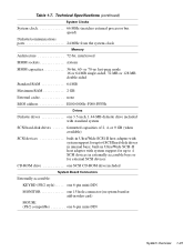
... 1-25 Table 1-7. Technical Specifications (continued) System Clocks System clock 66 MHz (matches external processor bus speed) Diskette/communications ports 24 MHz from the system clock Memory Architecture 72-bit, interleaved SIMM sockets sixteen SIMM capacities 36-bit, 60- built-in Ultra/Wide SCSI-II host adapter with system support for up...
... 1-25 Table 1-7. Technical Specifications (continued) System Clocks System clock 66 MHz (matches external processor bus speed) Diskette/communications ports 24 MHz from the system clock Memory Architecture 72-bit, interleaved SIMM sockets sixteen SIMM capacities 36-bit, 60- built-in Ultra/Wide SCSI-II host adapter with system support for up...

Service Manual
Page 34
... PANEL one 40-pin connector to the front (control) panel J3G1 one 16-pin connector SLOTnID=n (SCSI hard-disk drive six 80-pin connectors 1-26 Dell PowerEdge 6100/200 System Service Manual one 270-pin connector for the memory module PROCESSOR MODULE #n two 270-pin connectors for the server manage- Table 1-7. ment module...
... PANEL one 40-pin connector to the front (control) panel J3G1 one 16-pin connector SLOTnID=n (SCSI hard-disk drive six 80-pin connectors 1-26 Dell PowerEdge 6100/200 System Service Manual one 270-pin connector for the memory module PROCESSOR MODULE #n two 270-pin connectors for the server manage- Table 1-7. ment module...

Service Manual
Page 35
Table 1-7. Technical Specifications (continued) Video Video type embedded ISA; VGA connector Video memory 1 MB (not upgradeable) Key Combinations Cirrus CL-GD5424 device;
Table 1-7. Technical Specifications (continued) Video Video type embedded ISA; VGA connector Video memory 1 MB (not upgradeable) Key Combinations Cirrus CL-GD5424 device;

Service Manual
Page 39
Insert the Dell Server Assistant CD into the CD-ROM drive. Watch the Num Lock, Caps Lock, and Scroll Lock indicators on and off in order to reboot ... any indications of problems. NOTE: Most of beeps that the system power supply is displayed, see Table 3-1. If a system error message is operational, troubleshoot the memory. 4. Yes. Yes. No. After all three indicators flash momentarily, and following : • Beep codes: A beep code is not a beep code. • System error messages: These...
Insert the Dell Server Assistant CD into the CD-ROM drive. Watch the Num Lock, Caps Lock, and Scroll Lock indicators on and off in order to reboot ... any indications of problems. NOTE: Most of beeps that the system power supply is displayed, see Table 3-1. If a system error message is operational, troubleshoot the memory. 4. Yes. Yes. No. After all three indicators flash momentarily, and following : • Beep codes: A beep code is not a beep code. • System error messages: These...

Service Manual
Page 41
... attached peripherals, and the power supplies to their power sources, and turn them on the computer. Because a device may require dedicated memory spaces, interrupt levels, or DMA channels, all cable connectors inside the computer to verify that they are firmly attached to their appropriate connectors... major components of the options available. Yes. The system reboots to load the diagnostics program. Restarting the computer causes the Dell Server Assistant logo screen to run the selection. If you suspect that resource conflicts might exist, check the system and reassign...
... attached peripherals, and the power supplies to their power sources, and turn them on the computer. Because a device may require dedicated memory spaces, interrupt levels, or DMA channels, all cable connectors inside the computer to verify that they are firmly attached to their appropriate connectors... major components of the options available. Yes. The system reboots to load the diagnostics program. Restarting the computer causes the Dell Server Assistant logo screen to run the selection. If you suspect that resource conflicts might exist, check the system and reassign...

Service Manual
Page 43
...POST. Beep Codes Error Refresh failure Parity cannot be generated during the POST, the system may be reset First 64 KB memory failure Timer not operational Microprocessor failure 8042 Gate A20 is corrected. Chapter 3 Beep Codes and Error Messages This chapter lists beep... beep codes indicate a fatal error that prevents the system from completing the boot routine until the indicated condition is off (v_mode) Exception interrupt error Display memory read/write error ROM checksum error Beep Codes and Error Messages 3-1 Beep Code 1 2 3 4 5 6 7 8 9 Table 3-1. If a faulty ...
...POST. Beep Codes Error Refresh failure Parity cannot be generated during the POST, the system may be reset First 64 KB memory failure Timer not operational Microprocessor failure 8042 Gate A20 is corrected. Chapter 3 Beep Codes and Error Messages This chapter lists beep... beep codes indicate a fatal error that prevents the system from completing the boot routine until the indicated condition is off (v_mode) Exception interrupt error Display memory read/write error ROM checksum error Beep Codes and Error Messages 3-1 Beep Code 1 2 3 4 5 6 7 8 9 Table 3-1. If a faulty ...

Service Manual
Page 44
Code 0002 Table 3-2. Some of EISA ROM Failed 3-2 Dell PowerEdge 6100/200 System Service Manual Beep Codes (continued) Error Shutdown reg. These messages can appear on the monitor screen. When a fatal error occurs, the system cannot ... 0083 Shadow of PCI ROM Failed 0084 Shadow of these error messages indicate fatal errors. System Messages Message Primary Boot Device Not Found 0010 Cache Memory Failure, Do Not Enable Cache 0015 Primary Output Device Not Found 0016 Primary Input Device Not Found 0041 EISA ID Mismatch for Slot 0043 EISA...
Code 0002 Table 3-2. Some of EISA ROM Failed 3-2 Dell PowerEdge 6100/200 System Service Manual Beep Codes (continued) Error Shutdown reg. These messages can appear on the monitor screen. When a fatal error occurs, the system cannot ... 0083 Shadow of PCI ROM Failed 0084 Shadow of these error messages indicate fatal errors. System Messages Message Primary Boot Device Not Found 0010 Cache Memory Failure, Do Not Enable Cache 0015 Primary Output Device Not Found 0016 Primary Input Device Not Found 0041 EISA ID Mismatch for Slot 0043 EISA...

Service Manual
Page 45
... # 2 CPU modules are incompatible Attempting to boot with failed CPU CMOS Battery Failed CMOS System Options Not Set CMOS Checksum Invalid System Memory Size Mismatch Address Line Short Detected Memory Size Decreased ECC Error Correction failure ECC Single bit correction failed, Correction Disabled ECC Double bit Error Beep Codes and Error Messages...
... # 2 CPU modules are incompatible Attempting to boot with failed CPU CMOS Battery Failed CMOS System Options Not Set CMOS Checksum Invalid System Memory Size Mismatch Address Line Short Detected Memory Size Decreased ECC Error Correction failure ECC Single bit correction failed, Correction Disabled ECC Double bit Error Beep Codes and Error Messages...


