
Intel Xeon Processor E7-2800/4800/8800 Product Family - Information Update
Page 3
... handle (PowerEdge M910 II). Important Information The following new Dell PowerEdge systems support the Intel Xeon processor E7-2800/4800/8800 product family: • PowerEdge R810 II • PowerEdge R910 II • PowerEdge M910 II These systems are marked with a limited feature set. Figure 1. See Figure 1. Identifying new Dell PowerEdge Systems With Roman Numeral II PowerEdge R910 II PowerEdge R810 II PowerEdge M910 II...
... handle (PowerEdge M910 II). Important Information The following new Dell PowerEdge systems support the Intel Xeon processor E7-2800/4800/8800 product family: • PowerEdge R810 II • PowerEdge R910 II • PowerEdge M910 II These systems are marked with a limited feature set. Figure 1. See Figure 1. Identifying new Dell PowerEdge Systems With Roman Numeral II PowerEdge R910 II PowerEdge R810 II PowerEdge M910 II...

Dell PowerEdge M1000e Configuration Guide
Page 15
Front Panel Features-PowerEdge M910 1 2 6 5 4 3 1 blade-handle release button 2 hard drives (2) 3 blade status/identification indicator 4 USB connectors (3) 5 blade power button 6 blade power indicator About Your System 15 Blades Figure 1-7.
Front Panel Features-PowerEdge M910 1 2 6 5 4 3 1 blade-handle release button 2 hard drives (2) 3 blade status/identification indicator 4 USB connectors (3) 5 blade power button 6 blade power indicator About Your System 15 Blades Figure 1-7.

Hardware Owner's Manual
Page 5
..., M610x 132 Boot Settings Screen 133 Integrated Devices Screen 133 PCI IRQ Assignments Screen 135 Serial Communication Screen 135 Power Management Screen(PowerEdge M910, M710, M710HD, M610 and M610x Only 136 System Security Screen 137 Exit Screen 138 Entering the UEFI Boot Manager 139 UEFI Boot Manager Screen 139 ...
..., M610x 132 Boot Settings Screen 133 Integrated Devices Screen 133 PCI IRQ Assignments Screen 135 Serial Communication Screen 135 Power Management Screen(PowerEdge M910, M710, M710HD, M610 and M610x Only 136 System Security Screen 137 Exit Screen 138 Entering the UEFI Boot Manager 139 UEFI Boot Manager Screen 139 ...
Hardware Owner's Manual
Page 6
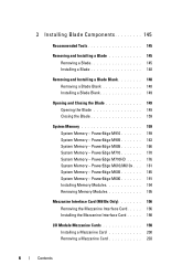
.../M610x . . . 181 System Memory - PowerEdge M905 163 System Memory - PowerEdge M710 170 System Memory - 3 Installing Blade Components 145 Recommended Tools 145 Removing and Installing a Blade 145 Removing a Blade 145 Installing a Blade 148... Closing the Blade 149 Opening the Blade 149 Closing the Blade 159 System Memory 159 System Memory - PowerEdge M605 185 System Memory - PowerEdge M805 166 System Memory - PowerEdge M910 159 System Memory - PowerEdge M600 191 Installing Memory Modules 194 Removing Memory Modules 195 Mezzanine Interface Card (M610x Only 196 Removing the...
.../M610x . . . 181 System Memory - PowerEdge M905 163 System Memory - PowerEdge M710 170 System Memory - 3 Installing Blade Components 145 Recommended Tools 145 Removing and Installing a Blade 145 Removing a Blade 145 Installing a Blade 148... Closing the Blade 149 Opening the Blade 149 Closing the Blade 159 System Memory 159 System Memory - PowerEdge M605 185 System Memory - PowerEdge M805 166 System Memory - PowerEdge M910 159 System Memory - PowerEdge M600 191 Installing Memory Modules 194 Removing Memory Modules 195 Mezzanine Interface Card (M610x Only 196 Removing the...
Hardware Owner's Manual
Page 7
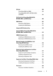
...Only 206 RAID Battery 207 Removing a RAID Battery 207 Installing the RAID Battery 212 Integrated NIC Hardware Key 213 Internal USB Key (PowerEdge M910, M710, M710HD, M610, and M610x Only 213 iDRAC6 Enterprise Card 214 Installing an iDRAC6 Enterprise Card 214 Removing an iDRAC6 Enterprise... Installing the LOM Riser Card 217 Expansion Cards and Expansion-Card Riser (PowerEdge M610x Only 217 Expansion Card Installation Guidelines 217 Installing an Expansion Card 218 Removing an Expansion Card 220 Expansion-Card Riser (PowerEdge M610x Only) . . . . 221 Removing the Expansion-Card Riser...
...Only 206 RAID Battery 207 Removing a RAID Battery 207 Installing the RAID Battery 212 Integrated NIC Hardware Key 213 Internal USB Key (PowerEdge M910, M710, M710HD, M610, and M610x Only 213 iDRAC6 Enterprise Card 214 Installing an iDRAC6 Enterprise Card 214 Removing an iDRAC6 Enterprise... Installing the LOM Riser Card 217 Expansion Cards and Expansion-Card Riser (PowerEdge M610x Only 217 Expansion Card Installation Guidelines 217 Installing an Expansion Card 218 Removing an Expansion Card 220 Expansion-Card Riser (PowerEdge M610x Only) . . . . 221 Removing the Expansion-Card Riser...
Hardware Owner's Manual
Page 8
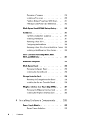
Removing a Processor 226 Installing a Processor 239 FlexMem Bridge (PowerEdge M910 Only) . . . . 241 HT Bridge Card (PowerEdge M905 Only) . . . . . 242 Blade System Board NVRAM Backup Battery. . . . . 245 Hard Drives 247 Hard Drive Installation ... System Board 258 Storage Controller Card 259 Removing the Storage Controller Board . . . . . 259 Installing the Storage Controller Board . . . . . 260 Midplane Interface Card (PowerEdge M610x) . . . . 261 Removing the Midplane Interface Card . . . . . 261 Installing the Midplane Interface Card 263 4 Installing Enclosure Components . . . . ....
Removing a Processor 226 Installing a Processor 239 FlexMem Bridge (PowerEdge M910 Only) . . . . 241 HT Bridge Card (PowerEdge M905 Only) . . . . . 242 Blade System Board NVRAM Backup Battery. . . . . 245 Hard Drives 247 Hard Drive Installation ... System Board 258 Storage Controller Card 259 Removing the Storage Controller Board . . . . . 259 Installing the Storage Controller Board . . . . . 260 Midplane Interface Card (PowerEdge M610x) . . . . 261 Removing the Midplane Interface Card . . . . . 261 Installing the Midplane Interface Card 263 4 Installing Enclosure Components . . . . ....
Hardware Owner's Manual
Page 11
6 Running System Diagnostics 303 Dell PowerEdge Diagnostics 303 System Diagnostics Features 303 When to Use the System Diagnostics 304 Running the System Diagnostics 304 Running the Embedded...PowerEdge M910 Jumper Settings 309 PowerEdge M905 Jumper Settings 310 PowerEdge M805 Jumper Settings 311 PowerEdge M710 Jumper Settings 312 PowerEdge M710HD Jumper Settings 313 PowerEdge M610/M610x Jumper Settings. . . . . 314 PowerEdge M600 Jumper Settings 315 System Board Connectors 316 PowerEdge M910 System Board 316 PowerEdge M905 System Board 318 PowerEdge M805 System Board 320 PowerEdge...
6 Running System Diagnostics 303 Dell PowerEdge Diagnostics 303 System Diagnostics Features 303 When to Use the System Diagnostics 304 Running the System Diagnostics 304 Running the Embedded...PowerEdge M910 Jumper Settings 309 PowerEdge M905 Jumper Settings 310 PowerEdge M805 Jumper Settings 311 PowerEdge M710 Jumper Settings 312 PowerEdge M710HD Jumper Settings 313 PowerEdge M610/M610x Jumper Settings. . . . . 314 PowerEdge M600 Jumper Settings 315 System Board Connectors 316 PowerEdge M910 System Board 316 PowerEdge M905 System Board 318 PowerEdge M805 System Board 320 PowerEdge...

Hardware Owner's Manual
Page 23
PowerEdge M910 1 2 6 5 4 3 1 blade handle release button 2 hard drives (2) 3 blade status/identification indicator 4 USB connectors (3) 5 blade power button 6 blade power indicator About Your System 23 Front Panel Features - Figure 1-7.
PowerEdge M910 1 2 6 5 4 3 1 blade handle release button 2 hard drives (2) 3 blade status/identification indicator 4 USB connectors (3) 5 blade power button 6 blade power indicator About Your System 23 Front Panel Features - Figure 1-7.
Hardware Owner's Manual
Page 30
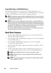
Hard-Drive Features • The PowerEdge M910 blades support up to two 2.5-inch SAS, SATA, or solid-state disk (SSD) hard drives. • The PowerEdge M905 and M805 blades support one or two hot-swappable 2.5-inch SAS hard drives. • The PowerEdge M710HD blade supports up to operate properly. NOTE:... the blade. 30 About Your System NOTE: These blades support only Dell-branded USB 2.0 drives. The drive must be horizontal and level to two hot-swappable 2.5-inch SAS or SSD hard drives. • The PowerEdge M710 blade supports up and selecting a boot device for the current boot...
Hard-Drive Features • The PowerEdge M910 blades support up to two 2.5-inch SAS, SATA, or solid-state disk (SSD) hard drives. • The PowerEdge M905 and M805 blades support one or two hot-swappable 2.5-inch SAS hard drives. • The PowerEdge M710HD blade supports up to operate properly. NOTE:... the blade. 30 About Your System NOTE: These blades support only Dell-branded USB 2.0 drives. The drive must be horizontal and level to two hot-swappable 2.5-inch SAS or SSD hard drives. • The PowerEdge M710 blade supports up and selecting a boot device for the current boot...

Hardware Owner's Manual
Page 113
...are clean and supported memory modules are identical and in a lock-step pair. See "General Memory Module Installation Guidelines - PowerEdge M910" on page 159. DIMMs disabled - The memory modules are Replace or reseat the not properly seated. Unsupported memory See...(s). Replace the memory modules. The memory module connectors may be exposed to dust. See "System Memory" on page 161. PowerEdge M910" on page 159. About Your System 113 Blade Messages (continued) Message Causes Corrective Actions DIMMs disabled - memory module(s). DIMMs...
...are clean and supported memory modules are identical and in a lock-step pair. See "General Memory Module Installation Guidelines - PowerEdge M910" on page 159. DIMMs disabled - The memory modules are Replace or reseat the not properly seated. Unsupported memory See...(s). Replace the memory modules. The memory module connectors may be exposed to dust. See "System Memory" on page 161. PowerEdge M910" on page 159. About Your System 113 Blade Messages (continued) Message Causes Corrective Actions DIMMs disabled - memory module(s). DIMMs...

Hardware Owner's Manual
Page 129
...and any installed expansion cards that have keyboards attached. System Date Sets the date on page 132. SATA Settings See "SATA Settings Screen (PowerEdge M610, M610x)" on the system's internal calendar. Integrated Devices See "Integrated Devices Screen" on the system's internal clock. System Setup ...or 102-key keyboards (does not apply to the keyboard or keyboard controller during the POST. Power Management See "Power Management Screen (PowerEdge M910, M710, M710HD, M610 and M610x Only)" on the system configuration. Select Do Not Report to suppress all error messages relating to ...
...and any installed expansion cards that have keyboards attached. System Date Sets the date on page 132. SATA Settings See "SATA Settings Screen (PowerEdge M610, M610x)" on the system's internal calendar. Integrated Devices See "Integrated Devices Screen" on the system's internal clock. System Setup ...or 102-key keyboards (does not apply to the keyboard or keyboard controller during the POST. Power Management See "Power Management Screen (PowerEdge M910, M710, M710HD, M610 and M610x Only)" on the system configuration. Select Do Not Report to suppress all error messages relating to ...
Hardware Owner's Manual
Page 131
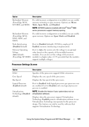
... per core is enabled. This feature can only be used by software that the modules support multiple voltages. Option Description Redundant Memory (PowerEdge M910, M710HD, and M600) If a valid memory configuration is installed, you can enable spare memory. NOTE: Disable this feature if your.... Options are Spare Mode and Disabled. If Enabled, memory interleaving is employed. Displays the bus speed of the processors. Redundant Memory (PowerEdge M910, M905, M805, and M605) If a valid memory configuration is installed, you can enable memory mirroring or spare memory. If set to...
... per core is enabled. This feature can only be used by software that the modules support multiple voltages. Option Description Redundant Memory (PowerEdge M910, M710HD, and M600) If a valid memory configuration is installed, you can enable spare memory. NOTE: Disable this feature if your.... Options are Spare Mode and Disabled. If Enabled, memory interleaving is employed. Displays the bus speed of the processors. Redundant Memory (PowerEdge M910, M905, M805, and M605) If a valid memory configuration is installed, you can enable memory mirroring or spare memory. If set to...

Hardware Owner's Manual
Page 133
... and the system has failed to boot, the system reattempts to do so. Using the System Setup Program and UEFI Boot Manager 133 Setting this (PowerEdge M910, M710, field to BIOS allows compatibility with non-UEFI M710HD, M610, and operating systems. M610x) NOTE: Setting this field to boot from hard drives in...
... and the system has failed to boot, the system reattempts to do so. Using the System Setup Program and UEFI Boot Manager 133 Setting this (PowerEdge M910, M710, field to BIOS allows compatibility with non-UEFI M710HD, M610, and operating systems. M610x) NOTE: Setting this field to boot from hard drives in...
Hardware Owner's Manual
Page 134
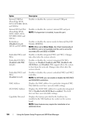
... the MAC address for Internal Dual SD Module (IDSDM). This field does not have user-selectable settings. Redundancy (Disabled default) (M910 and M710HD) Enables or disables the mirror mode for a particular integrated NIC. NOTE: Some features may require the installation of the... iSCSI Boot is enabled. Option Description Internal USB Port Enables or disables the system's internal USB port. (PowerEdge M910, M710, M710HD, M610, and M610x) Internal SD Card Port (PowerEdge M910, M905, M805, M710, M710HD, M610 and M610x) Enables or disables the system's internal SD card port...
... the MAC address for Internal Dual SD Module (IDSDM). This field does not have user-selectable settings. Redundancy (Disabled default) (M910 and M710HD) Enables or disables the mirror mode for a particular integrated NIC. NOTE: Some features may require the installation of the... iSCSI Boot is enabled. Option Description Internal USB Port Enables or disables the system's internal USB port. (PowerEdge M910, M710, M710HD, M610, and M610x) Internal SD Card Port (PowerEdge M910, M905, M805, M710, M710HD, M610 and M610x) Enables or disables the system's internal SD card port...

Hardware Owner's Manual
Page 135
... . Displays the failsafe baud rate used for console redirection through the IMC. I /O Acceleration Technology feature is set to Enabled, the I /OAT DMA Engine (Disabled default) (PowerEdge M910, M710, M610x, M610, M600) Embedded Video Controller (Enabled default) Description If set and the OS does not restart the system in the event of a timer...
... . Displays the failsafe baud rate used for console redirection through the IMC. I /O Acceleration Technology feature is set to Enabled, the I /OAT DMA Engine (Disabled default) (PowerEdge M910, M710, M610x, M610, M600) Embedded Video Controller (Enabled default) Description If set and the OS does not restart the system in the event of a timer...

Hardware Owner's Manual
Page 136
... Remote Terminal Type (VT 100/VT 220 default) Redirection After Boot (Enabled default) Description Select either VT 100/VT 220 or ANSI. Power Management Screen (PowerEdge M910, M710, M710HD, M610 and M610x Only) Option Power Management CPU Power and Performance Management Fan Power and Performance Management Memory Power and Performance Management Description...
... Remote Terminal Type (VT 100/VT 220 default) Redirection After Boot (Enabled default) Description Select either VT 100/VT 220 or ANSI. Power Management Screen (PowerEdge M910, M710, M710HD, M610 and M610x Only) Option Power Management CPU Power and Performance Management Fan Power and Performance Management Memory Power and Performance Management Description...

Hardware Owner's Manual
Page 159
... it is flush with four DIMMs per channel, for a total of the cover. This configuration permits the following maximum memory configurations: Up to 512 GB. PowerEdge M910 Your system supports DDR3 registered DIMMs (RDIMMS) only. 32 memory sockets are located on the system board, organized in the edges of the enclosure with...
... it is flush with four DIMMs per channel, for a total of the cover. This configuration permits the following maximum memory configurations: Up to 512 GB. PowerEdge M910 Your system supports DDR3 registered DIMMs (RDIMMS) only. 32 memory sockets are located on the system board, organized in the edges of the enclosure with...

Hardware Owner's Manual
Page 160
PowerEdge M910 B1 D1 B5 D5 B3 D3 B7 D7 B2 B6 D2 D6 B4 B8 D4 D8 A1 C1 A5 C5 A3 C3 A7 C7 A2 C2 A6 C6 A4 C4 A8 C8 160 Installing Blade Components Figure 3-12. Memory Locations -
PowerEdge M910 B1 D1 B5 D5 B3 D3 B7 D7 B2 B6 D2 D6 B4 B8 D4 D8 A1 C1 A5 C5 A3 C3 A7 C7 A2 C2 A6 C6 A4 C4 A8 C8 160 Installing Blade Components Figure 3-12. Memory Locations -

Hardware Owner's Manual
Page 161
... are installed. or dual-rank modules, the quad-rank modules must be installed in pairs, beginning with single- General Memory Module Installation Guidelines - PowerEdge M910 To ensure optimal performance of PowerEdge M910 Memory Configurations Total Physical Memory 4 GB 8 GB 16 GB 32 GB 64 GB 96 GB 128 GB 128 GB Memory Modules - Examples...
... are installed. or dual-rank modules, the quad-rank modules must be installed in pairs, beginning with single- General Memory Module Installation Guidelines - PowerEdge M910 To ensure optimal performance of PowerEdge M910 Memory Configurations Total Physical Memory 4 GB 8 GB 16 GB 32 GB 64 GB 96 GB 128 GB 128 GB Memory Modules - Examples...

Hardware Owner's Manual
Page 162
Examples of PowerEdge M910 Memory Configurations (continued) Total Physical Memory 128 GB 160 GB 192 GB 192 GB 256 GB 256 GB 384 GB 512 GB Memory Modules - Table 3-1. ...
Examples of PowerEdge M910 Memory Configurations (continued) Total Physical Memory 128 GB 160 GB 192 GB 192 GB 256 GB 256 GB 384 GB 512 GB Memory Modules - Table 3-1. ...


