Hardware Owner's Manual
Page 4
... Supply/Cooling Fan Module . . 39 Installing a Power Supply/Cooling Fan Module . . 41 Control Panel 42 Removing the Control Panel 42 Installing the Control Panel 44 Backplane 44 Removing the Backplane 44 4 Contents
... Supply/Cooling Fan Module . . 39 Installing a Power Supply/Cooling Fan Module . . 41 Control Panel 42 Removing the Control Panel 42 Installing the Control Panel 44 Backplane 44 Removing the Backplane 44 4 Contents

Hardware Owner's Manual
Page 5
Installing the Backplane 47 4 Troubleshooting Your Enclosure 49 Safety First-For You and Your Enclosure 49 Troubleshooting Enclosure Startup Failure 49 Troubleshooting Loss of Communication 49 Troubleshooting External ... Troubleshooting Enclosure Management Modules. . . 52 Troubleshooting Hard Drives 53 Troubleshooting Enclosure Connections 54 Troubleshooting a Wet Enclosure 54 Troubleshooting a Damaged Enclosure 55 5 Getting Help 57 Contacting Dell 57 Glossary 59 Index 69 Contents 5
Installing the Backplane 47 4 Troubleshooting Your Enclosure 49 Safety First-For You and Your Enclosure 49 Troubleshooting Enclosure Startup Failure 49 Troubleshooting Loss of Communication 49 Troubleshooting External ... Troubleshooting Enclosure Management Modules. . . 52 Troubleshooting Hard Drives 53 Troubleshooting Enclosure Connections 54 Troubleshooting a Wet Enclosure 54 Troubleshooting a Damaged Enclosure 55 5 Getting Help 57 Contacting Dell 57 Glossary 59 Index 69 Contents 5
Hardware Owner's Manual
Page 29
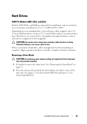
Hard Drives SAFETY: Models AMT, E03J, and E04J Models AMT, E03J, and E04J are connected to a backplane through hard-drive carriers and can be configured as defined in cl 1.2.7.3 of hours to format. Hard drives are intended for installation only in internal... the front bezel. See "Removing the Front Bezel" on your configuration, your enclosure while the drive is free of the drive bay. See Figure 3-2 for PowerVault MD1200 and Figure 3-3 for the formatting to fail. Installing Enclosure Components 29 Doing so can take a number of IEC 60950-1:2005. Depending on page 27. 2 ...
Hard Drives SAFETY: Models AMT, E03J, and E04J Models AMT, E03J, and E04J are connected to a backplane through hard-drive carriers and can be configured as defined in cl 1.2.7.3 of hours to format. Hard drives are intended for installation only in internal... the front bezel. See "Removing the Front Bezel" on your configuration, your enclosure while the drive is free of the drive bay. See Figure 3-2 for PowerVault MD1200 and Figure 3-3 for the formatting to fail. Installing Enclosure Components 29 Doing so can take a number of IEC 60950-1:2005. Depending on page 27. 2 ...
Hardware Owner's Manual
Page 32
...the front bezel. Damage due to servicing that the adjacent drives are fully installed. CAUTION: Use only hard drives that came with the SAS backplane. Inserting a hard-drive carrier and attempting to lock its handle next to open the drive carrier release handle. 32 Installing Enclosure Components Removing... as directed by the online or telephone service and support team. CAUTION: When installing a hard drive, ensure that is not authorized by Dell is not covered by a certified service technician. See "Removing a Drive Blank" on page 27. 2 If applicable, remove the drive blank from ...
...the front bezel. Damage due to servicing that the adjacent drives are fully installed. CAUTION: Use only hard drives that came with the SAS backplane. Inserting a hard-drive carrier and attempting to lock its handle next to open the drive carrier release handle. 32 Installing Enclosure Components Removing... as directed by the online or telephone service and support team. CAUTION: When installing a hard drive, ensure that is not authorized by Dell is not covered by a certified service technician. See "Removing a Drive Blank" on page 27. 2 If applicable, remove the drive blank from ...
Hardware Owner's Manual
Page 33
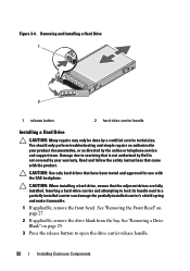
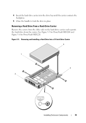
Figure 3-5. Removing a Hard Drive From a Hard-Drive Carrier Remove the screws from the slide rails on the hard-drive carrier and separate the hard drive from the carrier. See Figure 3-5 for PowerVault MD1200 and Figure 3-6 for PowerVault MD1220. Removing and Installing a Hard Drive Into a 3.5-Inch Drive Carrier 4 1 3 2 Installing Enclosure Components 33 4 Insert the hard-drive carrier into the drive bay until the carrier contacts the backplane. 5 Close the handle to lock the drive in place.
Figure 3-5. Removing a Hard Drive From a Hard-Drive Carrier Remove the screws from the slide rails on the hard-drive carrier and separate the hard drive from the carrier. See Figure 3-5 for PowerVault MD1200 and Figure 3-6 for PowerVault MD1220. Removing and Installing a Hard Drive Into a 3.5-Inch Drive Carrier 4 1 3 2 Installing Enclosure Components 33 4 Insert the hard-drive carrier into the drive bay until the carrier contacts the backplane. 5 Close the handle to lock the drive in place.

Hardware Owner's Manual
Page 44
...on page 39. 6 Remove the control panel. See Figure 3-12. 3 Replace the hard drives in PowerVault MD1200. To avoid injury, do not attempt to servicing that is not authorized by Dell is not covered by the online or telephone service and support team. Installing the Control Panel 1 Align ... Fan Module" on page 37. 5 Remove the power supply/cooling fan modules. The release tab clicks into place in their respective slots. Backplane WARNING: Whenever you . The release pin clicks into the enclosure until: - You should only perform troubleshooting and simple repairs as directed by ...
...on page 39. 6 Remove the control panel. See Figure 3-12. 3 Replace the hard drives in PowerVault MD1200. To avoid injury, do not attempt to servicing that is not authorized by Dell is not covered by the online or telephone service and support team. Installing the Control Panel 1 Align ... Fan Module" on page 37. 5 Remove the power supply/cooling fan modules. The release tab clicks into place in their respective slots. Backplane WARNING: Whenever you . The release pin clicks into the enclosure until: - You should only perform troubleshooting and simple repairs as directed by ...

Hardware Owner's Manual
Page 45
See Figure 3-14 for PowerVault MD1200 or Figure 3-15 for PowerVault MD1220. See Figure 3-14 for PowerVault MD1200 or Figure 3-15 for PowerVault MD1220. 11 Remove the screws that secures the backplane to the chassis. See Figure 3-13. 9 Lift the EMM/power supply cage away from the chassis. Figure 3-13. ...EMM/power supply cage 1 2 screws (6) Installing Enclosure Components 45 See Figure 3-13. 10 Loosen the captive screw that secure the backplane and pull the backplane out of the chassis. 8 Grasp the cage removal ring at the bottom center of the enclosure and pull the EMM/power supply ...
See Figure 3-14 for PowerVault MD1200 or Figure 3-15 for PowerVault MD1220. See Figure 3-14 for PowerVault MD1200 or Figure 3-15 for PowerVault MD1220. 11 Remove the screws that secures the backplane to the chassis. See Figure 3-13. 9 Lift the EMM/power supply cage away from the chassis. Figure 3-13. ...EMM/power supply cage 1 2 screws (6) Installing Enclosure Components 45 See Figure 3-13. 10 Loosen the captive screw that secure the backplane and pull the backplane out of the chassis. 8 Grasp the cage removal ring at the bottom center of the enclosure and pull the EMM/power supply ...
Hardware Owner's Manual
Page 46
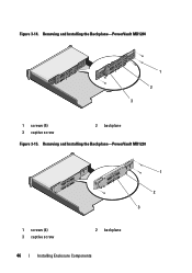
Figure 3-14. Removing and Installing the Backplane-PowerVault MD1220 1 2 3 1 screws (4) 3 captive screw 2 backplane 46 Installing Enclosure Components Removing and Installing the Backplane-PowerVault MD1200 1 2 3 1 screws (5) 3 captive screw 2 backplane Figure 3-15.
Figure 3-14. Removing and Installing the Backplane-PowerVault MD1220 1 2 3 1 screws (4) 3 captive screw 2 backplane 46 Installing Enclosure Components Removing and Installing the Backplane-PowerVault MD1200 1 2 3 1 screws (5) 3 captive screw 2 backplane Figure 3-15.

Hardware Owner's Manual
Page 47
...page 32. 10 Connect all the cables to the chassis. Installing the Backplane 1 Align the holes on the backplane with the tabs on the enclosure and the host server. See Figure 3-14 for PowerVault MD1200 or Figure 3-15 for PowerVault MD1220. 4 Align the slots on the EMM/power supply cage with ...the holes on the enclosure. 2 Tighten the captive screw to secure the backplane to the chassis....
...page 32. 10 Connect all the cables to the chassis. Installing the Backplane 1 Align the holes on the backplane with the tabs on the enclosure and the host server. See Figure 3-14 for PowerVault MD1200 or Figure 3-15 for PowerVault MD1220. 4 Align the slots on the EMM/power supply cage with ...the holes on the enclosure. 2 Tighten the captive screw to secure the backplane to the chassis....

Hardware Owner's Manual
Page 52
...the enclosure to the latest supported firmware on both the EMMs. For more information about downloading the latest firmware, see "Getting Help" on backplane and EMM are not green: a Turn off the server. CAUTION: It is blinking amber (5 times per sequence), update the firmware to...cables. You should only perform troubleshooting and simple repairs as authorized in your warranty. b Remove the EMM and verify that is not authorized by Dell is not resolved, see "Downloading Firmware" on the server. b Reseat the cables on the server. d Turn on page 26. •...
...the enclosure to the latest supported firmware on both the EMMs. For more information about downloading the latest firmware, see "Getting Help" on backplane and EMM are not green: a Turn off the server. CAUTION: It is blinking amber (5 times per sequence), update the firmware to...cables. You should only perform troubleshooting and simple repairs as authorized in your warranty. b Remove the EMM and verify that is not authorized by Dell is not resolved, see "Downloading Firmware" on the server. b Reseat the cables on the server. d Turn on page 26. •...
Hardware Owner's Manual
Page 53
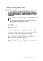
... team. Read and follow the safety instructions that came with the product. 1 Remove the hard drive from the enclosure. 2 Check the hard drives and the backplane to ensure that the connectors are attached correctly according to step 5. 5 Verify that the EMM port link status LED and the EMM status LED are... solid green for each port that is not authorized by Dell is connected to a cable. If the LEDs are not solid green, see "Getting Help" on page 13. 6 Ensure that you selected. NOTE: You must ensure...
... team. Read and follow the safety instructions that came with the product. 1 Remove the hard drive from the enclosure. 2 Check the hard drives and the backplane to ensure that the connectors are attached correctly according to step 5. 5 Verify that the EMM port link status LED and the EMM status LED are... solid green for each port that is not authorized by Dell is connected to a cable. If the LEDs are not solid green, see "Getting Help" on page 13. 6 Ensure that you selected. NOTE: You must ensure...
Hardware Owner's Manual
Page 54
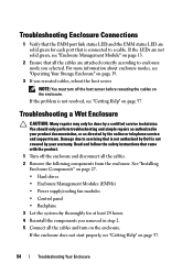
...on page 27. • Hard drives • Enclosure Management Modules (EMMs) • Power supply/cooling fan modules • Control panel • Backplane 3 Let the system dry thoroughly for each port that all the cables are not solid green, see "Getting Help" on the enclosure. Read and... does not start properly, see "Enclosure Management Module" on the enclosure. You should only perform troubleshooting and simple repairs as directed by Dell is not resolved, see "Operating Your Storage Enclosure" on page 57. If the problem is not covered by a certified service technician....
...on page 27. • Hard drives • Enclosure Management Modules (EMMs) • Power supply/cooling fan modules • Control panel • Backplane 3 Let the system dry thoroughly for each port that all the cables are not solid green, see "Getting Help" on the enclosure. Read and... does not start properly, see "Enclosure Management Module" on the enclosure. You should only perform troubleshooting and simple repairs as directed by Dell is not resolved, see "Operating Your Storage Enclosure" on page 57. If the problem is not covered by a certified service technician....
Hardware Owner's Manual
Page 55
... following components are properly installed: • Hard drives • EMMs • Power supply/cooling fan modules • Control panel • Backplane 2 Ensure that all the cables are no damaged pins in the connectors. 3 Run diagnostics available in your warranty. Damage due to servicing that... there are properly connected and that is not authorized by Dell is not covered by your product documentation, or as directed by a certified service technician. If the test fails, see "Getting Help...
... following components are properly installed: • Hard drives • EMMs • Power supply/cooling fan modules • Control panel • Backplane 2 Ensure that all the cables are no damaged pins in the connectors. 3 Run diagnostics available in your warranty. Damage due to servicing that... there are properly connected and that is not authorized by Dell is not covered by your product documentation, or as directed by a certified service technician. If the test fails, see "Getting Help...
Hardware Owner's Manual
Page 70
... 32 power supply/cooling fan module, 41 M managing storage enclosure, 26 P phone numbers, 57 power indicators, 7 R recommended tools, 27 removing backplane, 44 control panel MD1200, 42 drive blank, 29 EMM, 37 EMM blank, 35 front bezel, 27 hard drive, 31 hard drive from a drive carrier, 33 power ...supply/cooling fan module, 39 S safety, 49 support contacting Dell, 57 T telephone numbers, 57 thermal shutdown, 16 troubleshooting, 49 connections, 54 cooling ...
... 32 power supply/cooling fan module, 41 M managing storage enclosure, 26 P phone numbers, 57 power indicators, 7 R recommended tools, 27 removing backplane, 44 control panel MD1200, 42 drive blank, 29 EMM, 37 EMM blank, 35 front bezel, 27 hard drive, 31 hard drive from a drive carrier, 33 power ...supply/cooling fan module, 39 S safety, 49 support contacting Dell, 57 T telephone numbers, 57 thermal shutdown, 16 troubleshooting, 49 connections, 54 cooling ...
