
User Guide
Page 2
... Motherboard 1 Before You Begin...6 Parts NOT in the Kit 6 EVGA H55 Motherboard 7 Motherboard Specifications 7 Hardware Installation ...9 Safety Instructions...9 Preparing the Motherboard 10 Installing the CPU 10 Installing the CPU Fan 11 Installing System Memory (DIMMs 12 Installing the Motherboard 12 Installing the I/O Shield 13 Securing the Motherboard into a System Case 14 Connecting...
... Motherboard 1 Before You Begin...6 Parts NOT in the Kit 6 EVGA H55 Motherboard 7 Motherboard Specifications 7 Hardware Installation ...9 Safety Instructions...9 Preparing the Motherboard 10 Installing the CPU 10 Installing the CPU Fan 11 Installing System Memory (DIMMs 12 Installing the Motherboard 12 Installing the I/O Shield 13 Securing the Motherboard into a System Case 14 Connecting...
User Guide
Page 4
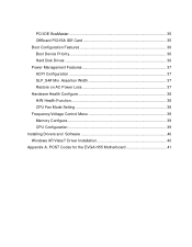
Assertion Width 37 Restore on AC Power Loss 37 Hardware Health Configure 38 H/W Health Function 38 CPU Fan Mode Setting 38 Frequency/Voltage Control Menu 39 Memory Configure 39 CPU Configuration 39 Installing Drivers and Software 40 Windows XP/Vista/7 Driver Installation 40 Appendix A. PCI IDE BusMaster 35 OffBoard PCI/ISA IDE Card 35 Boot Configuration Features 36 Boot Device Priority 36 Hard Disk Drives 36 Power Management Features 37 ACPI Configuration 37 SLP_S4# Min. POST Codes for the EVGA H55 Motherboard 41
Assertion Width 37 Restore on AC Power Loss 37 Hardware Health Configure 38 H/W Health Function 38 CPU Fan Mode Setting 38 Frequency/Voltage Control Menu 39 Memory Configure 39 CPU Configuration 39 Installing Drivers and Software 40 Windows XP/Vista/7 Driver Installation 40 Appendix A. PCI IDE BusMaster 35 OffBoard PCI/ISA IDE Card 35 Boot Configuration Features 36 Boot Device Priority 36 Hard Disk Drives 36 Power Management Features 37 ACPI Configuration 37 SLP_S4# Min. POST Codes for the EVGA H55 Motherboard 41
User Guide
Page 6
... right to install and connect your new EVGA H55 Motherboard. Before You Begin... However, it does not contain the following items that must be purchased separately to make the motherboard functional. Intel Socket 1156 Processor DDR3 System Memory Socket 1156 or Socket 775... Cooling fan PCI Express or PCI Graphics Card Power Supply EVGA assumes you will need to reinstall an operating system even though the current hard...
... right to install and connect your new EVGA H55 Motherboard. Before You Begin... However, it does not contain the following items that must be purchased separately to make the motherboard functional. Intel Socket 1156 Processor DDR3 System Memory Socket 1156 or Socket 775... Cooling fan PCI Express or PCI Graphics Card Power Supply EVGA assumes you will need to reinstall an operating system even though the current hard...
User Guide
Page 7
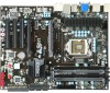
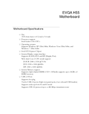
EVGA H55 Motherboard Motherboard Specifications Size ATX form factor of DDR3 memory. USB 2.0 Ports Supports hot plug Twelve USB 2.0 ports (Eight rear panel ports, four onboard USB headers) Supports wake-up from S1 and S3 mode ... Mbps transmission rate With Intel Core i3 CPU install support: D-SUB: 2048 x 1536 @75 Hz DVI: 1920 x 1200 @60Hz DP: 2560 x 1600 @60Hz System Memory support Supports triple channel DDR3-1333+. Officially supports up to 16GBs of 12 inch x 9.6 inch Processor support Intel Socket 1156 CPU's Operating systems...
EVGA H55 Motherboard Motherboard Specifications Size ATX form factor of DDR3 memory. USB 2.0 Ports Supports hot plug Twelve USB 2.0 ports (Eight rear panel ports, four onboard USB headers) Supports wake-up from S1 and S3 mode ... Mbps transmission rate With Intel Core i3 CPU install support: D-SUB: 2048 x 1536 @75 Hz DVI: 1920 x 1200 @60Hz DP: 2560 x 1600 @60Hz System Memory support Supports triple channel DDR3-1333+. Officially supports up to 16GBs of 12 inch x 9.6 inch Processor support Intel Socket 1156 CPU's Operating systems...
User Guide
Page 9
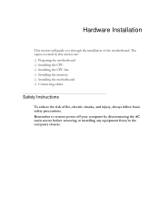
Remember to remove power off your computer by disconnecting the AC main source before removing or installing any equipment from/to the computer chassis. The topics covered in this section are: Preparing the motherboard Installing the CPU Installing the CPU fan Installing the memory Installing the motherboard Connecting cables Safety Instructions To reduce the risk of the motherboard. Hardware Installation This section will guide you through the installation of fire, electric shocks, and injury, always follow basic safety precautions.
Remember to remove power off your computer by disconnecting the AC main source before removing or installing any equipment from/to the computer chassis. The topics covered in this section are: Preparing the motherboard Installing the CPU Installing the CPU fan Installing the memory Installing the motherboard Connecting cables Safety Instructions To reduce the risk of the motherboard. Hardware Installation This section will guide you through the installation of fire, electric shocks, and injury, always follow basic safety precautions.
User Guide
Page 12
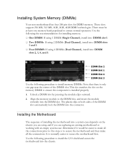
... into the chassis. The plastic clips at least one gap near the center of the DIMM slot. Use the following the recommendations for DDR3 memory. Installing the Motherboard The sequence of the DIMM slot automatically lock the DIMM into the DIMM slot. DIMM Slot 2 DIMM Slot 1 DIMM ...If using and if you are using 4 DIMMs (Dual Channel), install into a system case depends on the memory DIMM to ensure the component is only one memory bank populated to install memory DIMMs. Note that there is installed properly. 1. It is normally easier to secure the motherboard and then make...
... into the chassis. The plastic clips at least one gap near the center of the DIMM slot. Use the following the recommendations for DDR3 memory. Installing the Motherboard The sequence of the DIMM slot automatically lock the DIMM into the DIMM slot. DIMM Slot 2 DIMM Slot 1 DIMM ...If using and if you are using 4 DIMMs (Dual Channel), install into a system case depends on the memory DIMM to ensure the component is only one memory bank populated to install memory DIMMs. Note that there is installed properly. 1. It is normally easier to secure the motherboard and then make...
User Guide
Page 24
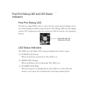
... connector indicate the system's status. POWER LED (Green): When the System is powered on: This LED is on. DIMM LED (Orange): When the Memory slot is functional: This LED is on. STANDBY LED (Blue): When the System is in Standby Mode: This LED is on as long as...
... connector indicate the system's status. POWER LED (Green): When the System is powered on: This LED is on. DIMM LED (Orange): When the Memory slot is functional: This LED is on. STANDBY LED (Blue): When the System is in Standby Mode: This LED is on as long as...

User Guide
Page 27
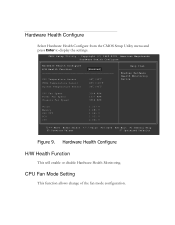
...; Hardware Health Configure Use this menu to view system vitals. Frequency/Voltage Control Use this menu to optimize system performance and configure clocks, voltages, memory timings, and more. Load Optimal Defaults Load default system settings. Discard Changes Use this command to abandon all setting changes and exit setup...
...; Hardware Health Configure Use this menu to view system vitals. Frequency/Voltage Control Use this menu to optimize system performance and configure clocks, voltages, memory timings, and more. Load Optimal Defaults Load default system settings. Discard Changes Use this command to abandon all setting changes and exit setup...

User Guide
Page 28
... Processor Intel(R) Core(TM) CPU Speed :3466MHz Count :1 670 @ 3.47GHz Help Item Use [ENTER] , [TAB] Or [SHIFT-TAB] to the previous menu, press Esc. System Memory Size :8120MB System Time System Date [13:37:00] [Fri 07/16/2010] Move Enter:Select +/-/:Value F10:Save ESC:Exit F1:General Help F7...
... Processor Intel(R) Core(TM) CPU Speed :3466MHz Count :1 670 @ 3.47GHz Help Item Use [ENTER] , [TAB] Or [SHIFT-TAB] to the previous menu, press Esc. System Memory Size :8120MB System Time System Date [13:37:00] [Fri 07/16/2010] Move Enter:Select +/-/:Value F10:Save ESC:Exit F1:General Help F7...
User Guide
Page 38
CPU Fan Speed Power Fan Speed Chassis Fan Speed :3264 RPM :1337 RPM :3864 RPM VCore Memory CPU VTT PCH +5V :1.337 V :1.481 V :1.021 V :1.031 V :4.961 V Move Enter:Select +/-/:Value F10:Save ESC:Exit F1:General Help F5:Previous Values F7:Optimized ...
CPU Fan Speed Power Fan Speed Chassis Fan Speed :3264 RPM :1337 RPM :3864 RPM VCore Memory CPU VTT PCH +5V :1.337 V :1.481 V :1.021 V :1.031 V :4.961 V Move Enter:Select +/-/:Value F10:Save ESC:Exit F1:General Help F5:Previous Values F7:Optimized ...

User Guide
Page 39
... Technology, CPU SpeedStep, or CPU power saving options. Copyright (C) 1985-2005, American Megatrends Frequency/Voltage Control Memory Configure CPU Configuration [Press Enter] [Press Enter] Item Help Target CPU Frequency: 3466 MHz (133x26) Target Memory Frequency: 1333 MHz (2:10) CPU Multiplier Setting [26] CPU Frequency Setting [Auto] PCIE Frequency Setting [100...
... Technology, CPU SpeedStep, or CPU power saving options. Copyright (C) 1985-2005, American Megatrends Frequency/Voltage Control Memory Configure CPU Configuration [Press Enter] [Press Enter] Item Help Target CPU Frequency: 3466 MHz (133x26) Target Memory Frequency: 1333 MHz (2:10) CPU Multiplier Setting [26] CPU Frequency Setting [Auto] PCIE Frequency Setting [100...
User Guide
Page 42
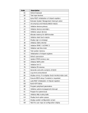
... System Management interrupt vector Uncompress and initialize BIOS module Initialize devices primary Initialize devices secondary Initialize output devices Allocate memory for ADM module Initialize silent boot module Display sign-on message Initialize USB controller Initialize DMAC-1 & DMAC-2 Initialize real... time clock Test system memory Initialization of chipset registers Detect coprocessor Update CMOS memory size Initialize NUM-LOCK Initialize Int-13 Initialize IPL devices Generate and write contents of ESCD Log...
... System Management interrupt vector Uncompress and initialize BIOS module Initialize devices primary Initialize devices secondary Initialize output devices Allocate memory for ADM module Initialize silent boot module Display sign-on message Initialize USB controller Initialize DMAC-1 & DMAC-2 Initialize real... time clock Test system memory Initialization of chipset registers Detect coprocessor Update CMOS memory size Initialize NUM-LOCK Initialize Int-13 Initialize IPL devices Generate and write contents of ESCD Log...

User Guide
Page 44
... HSF - Institute of Terms ACPI - EVGA Glossary of Electrical and Electronics Engineers IGP - Digital Video Interface FDC - Heat Sink Fan I/O - Integrated Drive Electronics IEEE - Alternate Frame Rendering APIC - Dual In-line Memory Module DRAM - For The Win! Gigahertz... GPU - Complementary Metal-Oxide Semiconductor CPU - Dynamic random access memory DVD - Graphics Processing Unit HDD - High Precision Event Timer HT - Interrupt Request JBOD - Basic Input Output System CD-ROM - Advanced Programmable Interrupt Controller BIOS - Central Processing Unit D-ICE...
... HSF - Institute of Terms ACPI - EVGA Glossary of Electrical and Electronics Engineers IGP - Digital Video Interface FDC - Heat Sink Fan I/O - Integrated Drive Electronics IEEE - Alternate Frame Rendering APIC - Dual In-line Memory Module DRAM - For The Win! Gigahertz... GPU - Complementary Metal-Oxide Semiconductor CPU - Dynamic random access memory DVD - Graphics Processing Unit HDD - High Precision Event Timer HT - Interrupt Request JBOD - Basic Input Output System CD-ROM - Advanced Programmable Interrupt Controller BIOS - Central Processing Unit D-ICE...