

Complete Owner's Guide (English)
Page 27
... any spills or spatters. Cleaning And Care 27 Disconnect the power cord before cleaning or leave the door open to the interior surfaces; Stainless Steel Trim-Kit Cleaners which are also dishwasher-proof. Touch Control Panel Wipe the panel with a cloth dampened slightly with a soft cloth. Do not scrub or use a mild... be cleaned with a damp cloth. Close door and press STOP/CLEAR. Turntable/Turntable Support The turntable and turntable support can be removed for stainless steel trim-kit. DO NOT USE ABRASIVE OR HARSH CLEANERS OR SCOURING PADS.
... any spills or spatters. Cleaning And Care 27 Disconnect the power cord before cleaning or leave the door open to the interior surfaces; Stainless Steel Trim-Kit Cleaners which are also dishwasher-proof. Touch Control Panel Wipe the panel with a cloth dampened slightly with a soft cloth. Do not scrub or use a mild... be cleaned with a damp cloth. Close door and press STOP/CLEAR. Turntable/Turntable Support The turntable and turntable support can be removed for stainless steel trim-kit. DO NOT USE ABRASIVE OR HARSH CLEANERS OR SCOURING PADS.

Complete Owner's Guide (English)
Page 29
Approx. 44.5 lb EI27MO45T EI30MO45T Trim Kit Dimensions 27"(W) x 18 1/16"(H) x 2 3/4"(D) 30"(W) x 18 1/16"(H) x 2 3/4"(D) * The International Electrotechnical Commission's standardized method for use in USA or Canada. Federal Communications Commission Authorized. DHHS - Specifications ...
Approx. 44.5 lb EI27MO45T EI30MO45T Trim Kit Dimensions 27"(W) x 18 1/16"(H) x 2 3/4"(D) 30"(W) x 18 1/16"(H) x 2 3/4"(D) * The International Electrotechnical Commission's standardized method for use in USA or Canada. Federal Communications Commission Authorized. DHHS - Specifications ...

Installation Instructions (All Languages)
Page 1
... A (1 3/16" length) QTY 2 4) Screw B (1 3/4" length) QTY 4 READ AND SAVE THESE INSTRUCTIONS FOR FUTURE REFERENCE. Important - Remove the turntable from the oven cavity. • Because the kit includes metal parts, caution should retain for local inspector's use and for this oven are 115-120 volts AC, 15 amps or larger. The electrical... to DISCONNECT THE PLUG of injury. • Do not remove permanently affixed labels, warnings, or plates from the electrical outlet before installing the built-in trim kit. IMPORTANT: SAVE FOR LOCAL ELECTRICAL INSPECTOR'S USE.
... A (1 3/16" length) QTY 2 4) Screw B (1 3/4" length) QTY 4 READ AND SAVE THESE INSTRUCTIONS FOR FUTURE REFERENCE. Important - Remove the turntable from the oven cavity. • Because the kit includes metal parts, caution should retain for local inspector's use and for this oven are 115-120 volts AC, 15 amps or larger. The electrical... to DISCONNECT THE PLUG of injury. • Do not remove permanently affixed labels, warnings, or plates from the electrical outlet before installing the built-in trim kit. IMPORTANT: SAVE FOR LOCAL ELECTRICAL INSPECTOR'S USE.

Installation Instructions (All Languages)
Page 2
... 20" (50.8 cm). I J 4" (10.2 cm) installation over an electric wall oven 2" (5.1 cm) minimum gap PRODUCT DIMENSIONS EI30M045T Trim Kit A B C D E 30" (76.2 cm) 18 1/16" (45.9 cm) 2 5/16" (5.9 cm) 24" (60.96 cm) 13 3/8" (33.9 cm) EI27M045T Trim Kit A B C D E 27" (68.6 cm) 18 1/16" (45.9 cm) 2 5/16" (5.9 cm) 24" (60.96 cm) 13 3/8" (33.9 cm...
... 20" (50.8 cm). I J 4" (10.2 cm) installation over an electric wall oven 2" (5.1 cm) minimum gap PRODUCT DIMENSIONS EI30M045T Trim Kit A B C D E 30" (76.2 cm) 18 1/16" (45.9 cm) 2 5/16" (5.9 cm) 24" (60.96 cm) 13 3/8" (33.9 cm) EI27M045T Trim Kit A B C D E 27" (68.6 cm) 18 1/16" (45.9 cm) 2 5/16" (5.9 cm) 24" (60.96 cm) 13 3/8" (33.9 cm...
Installation Instructions (All Languages)
Page 3
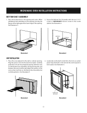
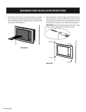
Plug the power cord into the control panel to the slots on the Bottom Duct Assembly. Snap the built in trim kit into the electrical outlet. See Illustration 5. Illustration 4 Shape on the Bottom Duct Assembly, but not fully pushed in place. Secure the Bottom Duct ...of the oven so that it will be tight against the lower edge of the opening . See Illustration 2. 2. Locate tabs on the built in trim kit to lock in . MICROWAVE OVEN INSTALLAITlluIsOtrNatioInN1STRUCTIONS BOTTOM DUCT ASSEMBLY 1. Slide the oven on control panel. Avoid pinching the cord between the oven and the ...
Plug the power cord into the control panel to the slots on the Bottom Duct Assembly. Snap the built in trim kit into the electrical outlet. See Illustration 5. Illustration 4 Shape on the Bottom Duct Assembly, but not fully pushed in place. Secure the Bottom Duct ...of the oven so that it will be tight against the lower edge of the opening . See Illustration 2. 2. Locate tabs on the built in trim kit to lock in . MICROWAVE OVEN INSTALLAITlluIsOtrNatioInN1STRUCTIONS BOTTOM DUCT ASSEMBLY 1. Slide the oven on control panel. Avoid pinching the cord between the oven and the ...
Installation Instructions (All Languages)
Page 4
Make sure that the feet of the oven are fitted into the cabinet so that the kit now rests flush with four screws B to guide the holes. Attach the built-in order to oven face. See Illustration 7. Adjust the frame ...is even. MICROWAVE OVEN INSTALLATION INSTRUCTIONS 3. See Illustration 6. 4. Pre-drill 4 holes using an ¹⁄₈" bit, using the kit to the cabinet. Important: Install top left mounting screw first in trim kit frame with the cabinet. Illustration 6 SCREW B SCREW B Illustration 7 SCREW B SCREW B TINS-B003MRR1 Push the position of the oven into...
Make sure that the feet of the oven are fitted into the cabinet so that the kit now rests flush with four screws B to guide the holes. Attach the built-in order to oven face. See Illustration 7. Adjust the frame ...is even. MICROWAVE OVEN INSTALLATION INSTRUCTIONS 3. See Illustration 6. 4. Pre-drill 4 holes using an ¹⁄₈" bit, using the kit to the cabinet. Important: Install top left mounting screw first in trim kit frame with the cabinet. Illustration 6 SCREW B SCREW B Illustration 7 SCREW B SCREW B TINS-B003MRR1 Push the position of the oven into...
Product Specifications Sheet (English)
Page 1
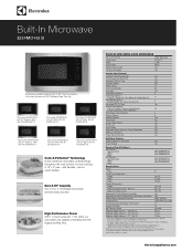
... Dimensions - Height 10-1/2" Width 17-3/8" Depth 18-5/8" Product Dimensions - Appliance must be evenly heated. Built-In Microwave EI24MO45I B Microwave includes choice of 30" or 27" Trim Kit available in combination with any Electrolux Electric Single Wall Oven and/or Warmer Drawer. (Not approved to be used in 3 colors (shown with 30" Stainless Steel...
... Dimensions - Height 10-1/2" Width 17-3/8" Depth 18-5/8" Product Dimensions - Appliance must be evenly heated. Built-In Microwave EI24MO45I B Microwave includes choice of 30" or 27" Trim Kit available in combination with any Electrolux Electric Single Wall Oven and/or Warmer Drawer. (Not approved to be used in 3 colors (shown with 30" Stainless Steel...

Product Specifications Sheet (English)
Page 2
... with another Electrolux built-in product, a minimum clearance of 2-7/8" required from bottom of Built-In Microwave cutout to top edge of 30" or 27" Trim Kit (ordered by individual part number and shipped separate). Built-In Microwave Specifications • Product Weight (Microwave with Trim Kit) - 51...product faceplates 30" or 27" Trim Kit Faceplate 18 1/16" (30") 30" (27") 27" Power cord location (right 24 " top rear) 16 1/4" min. 13 3/8 " 16 3/8" max. Appliance must be level and front of cabinet square for detailed instructions. Electrolux Major Appliances, N.A. mean we ...
... with another Electrolux built-in product, a minimum clearance of 2-7/8" required from bottom of Built-In Microwave cutout to top edge of 30" or 27" Trim Kit (ordered by individual part number and shipped separate). Built-In Microwave Specifications • Product Weight (Microwave with Trim Kit) - 51...product faceplates 30" or 27" Trim Kit Faceplate 18 1/16" (30") 30" (27") 27" Power cord location (right 24 " top rear) 16 1/4" min. 13 3/8 " 16 3/8" max. Appliance must be level and front of cabinet square for detailed instructions. Electrolux Major Appliances, N.A. mean we ...