

Printer Basics
Page 60
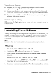
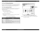
... posted for a minute or so. Wait until you are using a Macintosh and you do so. When connecting your Windows printer software or click Start or , select Programs or All Programs, select EPSON, and click EPSON Stylus Photo R260 Series Driver Update. Also make sure the USB cable is closed completely and no packing material remains in the...
... posted for a minute or so. Wait until you are using a Macintosh and you do so. When connecting your Windows printer software or click Start or , select Programs or All Programs, select EPSON, and click EPSON Stylus Photo R260 Series Driver Update. Also make sure the USB cable is closed completely and no packing material remains in the...
Printer Basics
Page 67
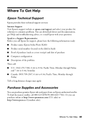
... Continue, then go to Epson or Epson Printers, then select Epson Printer Software Uninstall. Uninstalling Printer Software 67 For Macintosh OS X, make sure your printer software or program is securely connected and meets the system requirements on -screen instructions. 5. Click Start or , and select Programs or All Programs. 3. In the next window, select EPSON Stylus Photo R260 Series, and click OK...
... Continue, then go to Epson or Epson Printers, then select Epson Printer Software Uninstall. Uninstalling Printer Software 67 For Macintosh OS X, make sure your printer software or program is securely connected and meets the system requirements on -screen instructions. 5. Click Start or , and select Programs or All Programs. 3. In the next window, select EPSON Stylus Photo R260 Series, and click OK...
Printer Basics
Page 69
... Toll or long distance charges may apply. Speak to common problems. You can download drivers and documentation, get FAQs and troubleshooting advice, or e-mail Epson with your product for support, please have the following information ready: ■ Product name (Epson Stylus Photo R260) ■ Product serial number (located on the label in back) ■ Proof of...
... Toll or long distance charges may apply. Speak to common problems. You can download drivers and documentation, get FAQs and troubleshooting advice, or e-mail Epson with your product for support, please have the following information ready: ■ Product name (Epson Stylus Photo R260) ■ Product serial number (located on the label in back) ■ Proof of...
Service Manual
Page 24
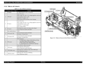
... 2-2. Motors & Sensors in the Printer Mechanism Operating Principles Overview 25 Motor/Sensor Name Function 1 Printhead F3-MACH head (6 colors x 90 nozzles) 2 CR motor Type: DC motor Drive voltage: 42V DC ± 5% (voltage applied to the driver) Coil resistance: 22.7Ω &#...Reflective photo interrupter 9 APG sensor Detecting items: APG position Type: Transmissive photo interrupter 10 CDR Guide sensor Detecting items: Up/Down status of the CDR Guide Type: Mechanical contact 11 CDR Tray sensor Detecting items: Presence of Motors & Sensors No. EPSON Stylus Photo R260/R265...
... 2-2. Motors & Sensors in the Printer Mechanism Operating Principles Overview 25 Motor/Sensor Name Function 1 Printhead F3-MACH head (6 colors x 90 nozzles) 2 CR motor Type: DC motor Drive voltage: 42V DC ± 5% (voltage applied to the driver) Coil resistance: 22.7Ω &#...Reflective photo interrupter 9 APG sensor Detecting items: APG position Type: Transmissive photo interrupter 10 CDR Guide sensor Detecting items: Up/Down status of the CDR Guide Type: Mechanical contact 11 CDR Tray sensor Detecting items: Presence of Motors & Sensors No. EPSON Stylus Photo R260/R265...
Service Manual
Page 25
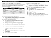
...to be reduced to one third the conventional size. „ Equips a 3.5inch Color TFT LCD as a system memory enabling a wide range of memory access. „ By employing a self-powered motor driver, the cost for supplying power to the RTC (5V) and USB HostVCC (...High Speed compatibility. † Operations to reduce power consumption The printer carries out the following boards. Revision B † Features of C653Main Board (R260/R265/R270) „ The newly employed SOC achieves throughput enhancement. EPSON Stylus Photo R260/R265/R270, R360/R380/R390 2.2 Electrical Circuit Operating Principles ...
...to be reduced to one third the conventional size. „ Equips a 3.5inch Color TFT LCD as a system memory enabling a wide range of memory access. „ By employing a self-powered motor driver, the cost for supplying power to the RTC (5V) and USB HostVCC (...High Speed compatibility. † Operations to reduce power consumption The printer carries out the following boards. Revision B † Features of C653Main Board (R260/R265/R270) „ The newly employed SOC achieves throughput enhancement. EPSON Stylus Photo R260/R265/R270, R360/R380/R390 2.2 Electrical Circuit Operating Principles ...
Service Manual
Page 27
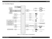
...EPSON Stylus Photo R260/R265/R270, R360/R380/R390 2.2.3 Circuit Block Diagram Flash-ROM (IC9) SDRAM (IC11) DDR-DRAM Data (IC7) Address Data Address RTC (IC3) CPU-ASIC (IC4) Serial Flash-ROM (IC5) LCD C658 Panel Board C658 Panel_B Board C658 STG Board CN4 CN3 CN1 USB (CN2) C653 PSB/PSE Board CN16 Motor Driver... (IC2) CN6 CN7 CN8 CN9 CN14 CN15 Head Driver (IC1) QM1, Q2, Q3 CN5 CN13 CN10 CN11 CN12 Operating Principles Figure 2-3. Circuit Block Diagram for R360/R380/...
...EPSON Stylus Photo R260/R265/R270, R360/R380/R390 2.2.3 Circuit Block Diagram Flash-ROM (IC9) SDRAM (IC11) DDR-DRAM Data (IC7) Address Data Address RTC (IC3) CPU-ASIC (IC4) Serial Flash-ROM (IC5) LCD C658 Panel Board C658 Panel_B Board C658 STG Board CN4 CN3 CN1 USB (CN2) C653 PSB/PSE Board CN16 Motor Driver... (IC2) CN6 CN7 CN8 CN9 CN14 CN15 Head Driver (IC1) QM1, Q2, Q3 CN5 CN13 CN10 CN11 CN12 Operating Principles Figure 2-3. Circuit Block Diagram for R360/R380/...
Service Manual
Page 28
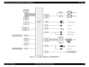
EPSON Stylus Photo R260/R265/R270, R360/R380/R390 Revision B Flash-ROM (IC1) SDRAM (IC2) RTC (IC3) Serial Flash-ROM (IC4) C653 Panel Board CN5 USB HOST (CN2) USB (CN1) C653 PSB/PSE Board CN3 CPU-ASIC (IC5) Motor Driver (IC8) CN8 CN7 CN6 CN4 CN14 CN13 Head Driver (IC7) Q2, Q5, Q6, Q7 CN16 CN10 CN11 CN12 CN15 Figure 2-4. Circuit Block Diagram for R260/R265/R270 CR Motor PF Motor PF Encoder Sensor APG Sensor PE Sensor CDR Guide Sensor CDR Tray Sensor Printhead CR Encoder Sensor PW Sensor C653 Head Board Operating Principles Electrical Circuit Operating Principles 29
EPSON Stylus Photo R260/R265/R270, R360/R380/R390 Revision B Flash-ROM (IC1) SDRAM (IC2) RTC (IC3) Serial Flash-ROM (IC4) C653 Panel Board CN5 USB HOST (CN2) USB (CN1) C653 PSB/PSE Board CN3 CPU-ASIC (IC5) Motor Driver (IC8) CN8 CN7 CN6 CN4 CN14 CN13 Head Driver (IC7) Q2, Q5, Q6, Q7 CN16 CN10 CN11 CN12 CN15 Figure 2-4. Circuit Block Diagram for R260/R265/R270 CR Motor PF Motor PF Encoder Sensor APG Sensor PE Sensor CDR Guide Sensor CDR Tray Sensor Printhead CR Encoder Sensor PW Sensor C653 Head Board Operating Principles Electrical Circuit Operating Principles 29
Service Manual
Page 32
...the window of the printer driver when a problem arises during various operations; "Difference in the Status Monitor 3 screen differs by destination. ON (0.8 sec.) - You can be checked with a LCD. ON (0.2 sec.) - OFF (0.4 sec.) Flashes as follows; Error Indication on EPSON Status Monitor 3 ... so on. 3.2.1 Error Indication Method The Stylus Photo R360/R380/R390 are displayed on the LCD. • Figure 1-1. EPSON Stylus Photo R260/R265/R270, R360/R380/R390 3.2 Error/Warning Indications This section describes how the printer indicates an error/warning status with the LCD...
...the window of the printer driver when a problem arises during various operations; "Difference in the Status Monitor 3 screen differs by destination. ON (0.8 sec.) - You can be checked with a LCD. ON (0.2 sec.) - OFF (0.4 sec.) Flashes as follows; Error Indication on EPSON Status Monitor 3 ... so on. 3.2.1 Error Indication Method The Stylus Photo R360/R380/R390 are displayed on the LCD. • Figure 1-1. EPSON Stylus Photo R260/R265/R270, R360/R380/R390 3.2 Error/Warning Indications This section describes how the printer indicates an error/warning status with the LCD...

Service Manual
Page 35
...Remedy Panel Board/ Panel FFC P/S ASSY USB cable Printer driver Main Board 1. When some parts need to be replaced or repaired, make sure to the printer and 1. using the Adjustment Program. Troubleshooting for the Stylus Photo R360/R380/R390/ R260/ R265/R270? 1. Replace the Panel FFC. ...Troubleshooting Troubleshooting by the LCD or STM3 screen. Is the P/S ASSY connector cable not connected to the Panel Board 1. EPSON Stylus Photo R260/R265/R270, R360/R380/R390 Revision B 3.3 Troubleshooting by Error Message The following tables provide troubleshooting procedure for each error ...
...Remedy Panel Board/ Panel FFC P/S ASSY USB cable Printer driver Main Board 1. When some parts need to be replaced or repaired, make sure to the printer and 1. using the Adjustment Program. Troubleshooting for the Stylus Photo R360/R380/R390/ R260/ R265/R270? 1. Replace the Panel FFC. ...Troubleshooting Troubleshooting by the LCD or STM3 screen. Is the P/S ASSY connector cable not connected to the Panel Board 1. EPSON Stylus Photo R260/R265/R270, R360/R380/R390 Revision B 3.3 Troubleshooting by Error Message The following tables provide troubleshooting procedure for each error ...

Service Manual
Page 54
... . Replace the Main Board. EPSON Stylus Photo R260/R265/R270, R360/R380/R390 Revision B 3.4.4 Problems with another one . Troubleshooting USB Connection Errors Possible Cause Check Point Remedy The printer driver has not been installed correctly. Does the USB communication between the printer and PC return to My Computer...electricity or etc.) Unsupported memory card Is the memory card a type not supported by be read the files? Is the printer driver associated with a new one . Is the Main Board damaged or broken? Replace the USB cable with Other Devices? Can...
... . Replace the Main Board. EPSON Stylus Photo R260/R265/R270, R360/R380/R390 Revision B 3.4.4 Problems with another one . Troubleshooting USB Connection Errors Possible Cause Check Point Remedy The printer driver has not been installed correctly. Does the USB communication between the printer and PC return to My Computer...electricity or etc.) Unsupported memory card Is the memory card a type not supported by be read the files? Is the printer driver associated with a new one . Is the Main Board damaged or broken? Replace the USB cable with Other Devices? Can...
Service Manual
Page 57
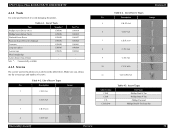
...Driver (No.1) Phillips Screw Driver (No.2) Flathead Screw Driver Precision Screw Driver #1 (flathead) Tweezers Long-nose pliers Acetate tape Metal straightedge 2 pins (thinner than Ø2mm) Note *: Commercially available Supplier* EPSON EPSON EPSON EPSON EPSON EPSON EPSON - EPSON Stylus Photo R260/R265/R270, R360/R380/R390 4.1.2 Tools Use only specified tools to avoid damaging the printer... Abbreviation C.B.S C.B.P C.P. Part No. 1080530 1080532 1080527 1080525 1080561 1080564 1003963 - 4.1.3 Screws The screws used in the printer are as shown in the table below. Table 4-1.
...Driver (No.1) Phillips Screw Driver (No.2) Flathead Screw Driver Precision Screw Driver #1 (flathead) Tweezers Long-nose pliers Acetate tape Metal straightedge 2 pins (thinner than Ø2mm) Note *: Commercially available Supplier* EPSON EPSON EPSON EPSON EPSON EPSON EPSON - EPSON Stylus Photo R260/R265/R270, R360/R380/R390 4.1.2 Tools Use only specified tools to avoid damaging the printer... Abbreviation C.B.S C.B.P C.P. Part No. 1080530 1080532 1080527 1080525 1080561 1080564 1003963 - 4.1.3 Screws The screws used in the printer are as shown in the table below. Table 4-1.
Service Manual
Page 68
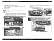
... Slide the Panel Unit upward to remove it upwards and disengage the two hooks. EPSON Stylus Photo R260/R265/R270, R360/R380/R390 4.2.6 Panel Unit † Parts/Components need to be removed in advance Paper Support / Printer Cover / Front Cover / Right Housing / Left Housing / USB Housing / Upper...8226;"4.1.8 Sharp Metal Edges (Danger!)" (p.62) 1. Panel Unit Slide, while pulling upward and disengage the hook [Backside] Removal Direction Screw Driver Figure 4-24. Removing the Connectors (Panel Unit) Revision B 2. Before starting, see the page given below to disengage the two hooks...
... Slide the Panel Unit upward to remove it upwards and disengage the two hooks. EPSON Stylus Photo R260/R265/R270, R360/R380/R390 4.2.6 Panel Unit † Parts/Components need to be removed in advance Paper Support / Printer Cover / Front Cover / Right Housing / Left Housing / USB Housing / Upper...8226;"4.1.8 Sharp Metal Edges (Danger!)" (p.62) 1. Panel Unit Slide, while pulling upward and disengage the hook [Backside] Removal Direction Screw Driver Figure 4-24. Removing the Connectors (Panel Unit) Revision B 2. Before starting, see the page given below to disengage the two hooks...
Service Manual
Page 73
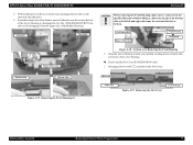
... „ Removing the Slot Cover (R360/R380/R390 only) 1. From the bottom side of the Printer, insert a flathead screw driver into the hole of the Lower Housing to disengage the two tabs. (With R260/R265/R270, the tabs can be disengaged from the upper side of the bottom ribs on the... inner left and right sides may be scratched heavily or broken. [Left inner side] Removal Direction Front Housing Bottom Rib Figure 4-38. EPSON Stylus Photo R260/R265/R270, R360/R380/R390 ...
... „ Removing the Slot Cover (R360/R380/R390 only) 1. From the bottom side of the Printer, insert a flathead screw driver into the hole of the Lower Housing to disengage the two tabs. (With R260/R265/R270, the tabs can be disengaged from the upper side of the bottom ribs on the... inner left and right sides may be scratched heavily or broken. [Left inner side] Removal Direction Front Housing Bottom Rib Figure 4-38. EPSON Stylus Photo R260/R265/R270, R360/R380/R390 ...
Service Manual
Page 76
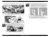
... Revision B „ When putting the Head FFC through the Ferrite Core, first straighten the fold of the pair of the USB Cable together with a screw driver or similar tool, and slide the FFC Holder upward to damage them. Routing the Head FFC (2) „ Screw the USB Board in the order given... Holder pulling the FFC out from the Middle Housing. Reinstalling the FFC Holder Disassembly/Assembly Removing Control Boards 77 FFC Holder Removal Direction Push Screw driver Positioning Pin FFC Holder Figure 4-47. EPSON Stylus Photo R260/R265/R270, R360/R380/R390 3.
... Revision B „ When putting the Head FFC through the Ferrite Core, first straighten the fold of the pair of the USB Cable together with a screw driver or similar tool, and slide the FFC Holder upward to damage them. Routing the Head FFC (2) „ Screw the USB Board in the order given... Holder pulling the FFC out from the Middle Housing. Reinstalling the FFC Holder Disassembly/Assembly Removing Control Boards 77 FFC Holder Removal Direction Push Screw driver Positioning Pin FFC Holder Figure 4-47. EPSON Stylus Photo R260/R265/R270, R360/R380/R390 3.
Service Manual
Page 90
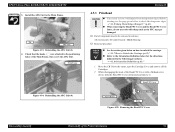
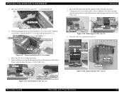
.... • "4.1.7 How to Unlock the Carriage (p.62)" „ Refer to avoid injury from sharp metal edges. Head FFC Cover Screw Driver Removal Direction Hook Figure 4-95. Reinstalling the APG Unit (3) 4. Removing the Head FFC Cover Disassembly/Assembly Disassembly of the Main Frame, then...the Cartridge Cover and remove all Ink Cartridges. 2. Check that the hooks ( ) are attached to the positioning holes of the Printer Mechanism 91 EPSON Stylus Photo R260/R265/R270, R360/R380/R390 3. While disengaging the hook of the Head FFC Cover with sharp ends as the FFC may get ...
.... • "4.1.7 How to Unlock the Carriage (p.62)" „ Refer to avoid injury from sharp metal edges. Head FFC Cover Screw Driver Removal Direction Hook Figure 4-95. Reinstalling the APG Unit (3) 4. Removing the Head FFC Cover Disassembly/Assembly Disassembly of the Main Frame, then...the Cartridge Cover and remove all Ink Cartridges. 2. Check that the hooks ( ) are attached to the positioning holes of the Printer Mechanism 91 EPSON Stylus Photo R260/R265/R270, R360/R380/R390 3. While disengaging the hook of the Head FFC Cover with sharp ends as the FFC may get ...
Service Manual
Page 91
Hook (2) Hook (2) [Left rear side] Figure 4-99. Rear side of the Printer Mechanism 92 Removing the FFC for CSIC Figure 4-96. Move the CR Unit to the home position). 8. Move the CR Unit to the left ... Hook (1) Revision B 7. Removing the CSIC Assy (2) 9. FFC for CSIC 4. Insert a flathead screw driver through the hole on the Head Board. Removing the CSIC Assy (3) Disassembly/Assembly Disassembly of CSIC Assy Removal Direction CSIC Assy Hook Connector Figure 4-100. EPSON Stylus Photo R260/R265/R270, R360/R380/R390 3. Disconnect the FFC from the connector ( ) on the...
Hook (2) Hook (2) [Left rear side] Figure 4-99. Rear side of the Printer Mechanism 92 Removing the FFC for CSIC Figure 4-96. Move the CR Unit to the home position). 8. Move the CR Unit to the left ... Hook (1) Revision B 7. Removing the CSIC Assy (2) 9. FFC for CSIC 4. Insert a flathead screw driver through the hole on the Head Board. Removing the CSIC Assy (3) Disassembly/Assembly Disassembly of CSIC Assy Removal Direction CSIC Assy Hook Connector Figure 4-100. EPSON Stylus Photo R260/R265/R270, R360/R380/R390 3. Disconnect the FFC from the connector ( ) on the...
Service Manual
Page 123
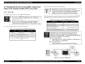
... PFP Base scale 1453980 Matte Paper-Heavyweight BRS --- (A4) Premium Glossy Photo Paper PFP --- (4 x 6) † Specified Scanner to perform the adjustment C A U T IO N „ Install the driver of about 2 minutes is necessary to be dried more than the ones ... Test Pattern Scanner PC Figure 5-11. System Configuration Banding Reduction System (BRS) Adjustment/ Paper Feed Amount Profile (PFP) Correction Printer 124 EPSON Stylus Photo R260/R265/R270, R360/R380/R390 Revision B 5.3 Banding Reduction System (BRS) Adjustment/ Paper Feed Amount Profile (PFP) Correction 5.3.1...
... PFP Base scale 1453980 Matte Paper-Heavyweight BRS --- (A4) Premium Glossy Photo Paper PFP --- (4 x 6) † Specified Scanner to perform the adjustment C A U T IO N „ Install the driver of about 2 minutes is necessary to be dried more than the ones ... Test Pattern Scanner PC Figure 5-11. System Configuration Banding Reduction System (BRS) Adjustment/ Paper Feed Amount Profile (PFP) Correction Printer 124 EPSON Stylus Photo R260/R265/R270, R360/R380/R390 Revision B 5.3 Banding Reduction System (BRS) Adjustment/ Paper Feed Amount Profile (PFP) Correction 5.3.1...
Service Manual
Page 129
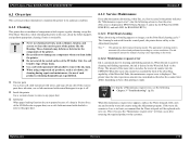
... the Pump. The appropriate cleaning mode is because the "Maintenance request error" will be activated from the control panel, the printer driver utility or the Adjustment program. If the exterior parts have ink stain, use of the PF Roller Unit. If the waste... ink counter using compressed air products; This printer takes the ink evaporation amount into the EEPROM. EPSON Stylus Photo R260/R265/R270, R360/R380/R390 Revision B 6.1 Overview This section provides information to maintain the printer in friction force of the printer like the Housing. These chemicals may occur ...
... the Pump. The appropriate cleaning mode is because the "Maintenance request error" will be activated from the control panel, the printer driver utility or the Adjustment program. If the exterior parts have ink stain, use of the PF Roller Unit. If the waste... ink counter using compressed air products; This printer takes the ink evaporation amount into the EEPROM. EPSON Stylus Photo R260/R265/R270, R360/R380/R390 Revision B 6.1 Overview This section provides information to maintain the printer in friction force of the printer like the Housing. These chemicals may occur ...


