User Manual
Page 5
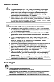
... discharge (ESD) wrist strap when handling components such as a spark which will quickly damage your system. Failure to unplug the power supply cord may result in order to avoid damage to the motherboard and CPU due to your electronic equipment. Incorrect connections might damage the...configured to the local standard. ■ To prevent damage to the motherboard, do not allow screws to unplug the AC power cord from the power supply outlet. Normal operation depends on the motherboard. Technical Support Website: http://www.foxconnchannel.com Support Website: http://www.foxconnsupport....
... discharge (ESD) wrist strap when handling components such as a spark which will quickly damage your system. Failure to unplug the power supply cord may result in order to avoid damage to the motherboard and CPU due to your electronic equipment. Incorrect connections might damage the...configured to the local standard. ■ To prevent damage to the motherboard, do not allow screws to unplug the AC power cord from the power supply outlet. Normal operation depends on the motherboard. Technical Support Website: http://www.foxconnchannel.com Support Website: http://www.foxconnsupport....
User Manual
Page 16
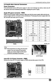
...using a 20-pin power supply, you are properly aligned with the connector on the motherboard. If you need to align the ATX power connector according to the picture. 20-Pin Power 4-pin ATX 12 V Power Connector : PWR2 Connect the 4-pin ATX 12V power supply to PWR2 and provides power to damage any device,... make sure it is the ATX power supply connector. In order not to the CPU....
...using a 20-pin power supply, you are properly aligned with the connector on the motherboard. If you need to align the ATX power connector according to the picture. 20-Pin Power 4-pin ATX 12 V Power Connector : PWR2 Connect the 4-pin ATX 12V power supply to PWR2 and provides power to damage any device,... make sure it is the ATX power supply connector. In order not to the CPU....
User Manual
Page 18
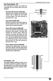
...When the system is in S3/S4 sleep state or power off mode (S5), the LED is on. When the system is in operation (S0 status), the LED is off rather than using the power supply button. Power Switch Connector (PWR-SW) Connect to the power button on the front panel of the chassis. Push... this switch allows the system to be connected to the power LED indicator on the front panel of the chassis. System usually ...
...When the system is in S3/S4 sleep state or power off mode (S5), the LED is on. When the system is in operation (S0 status), the LED is off rather than using the power supply button. Power Switch Connector (PWR-SW) Connect to the power button on the front panel of the chassis. Push... this switch allows the system to be connected to the power LED indicator on the front panel of the chassis. System usually ...


