User Manual
Page 5
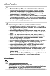
CAUTION Installation Precautions ■ Electrostatic discharge (ESD) is turned off before installing or removing CPU, memory, expansion cards or other peripherals. Failure to unplug the power supply cord may result in serious damage to your computer : ■ ... http://www.foxconnsupport.com/inquiry.aspx CPU Support List: http://www.foxconnsupport.com/cpusupportlist.aspx Memory, VGA Compatibility List: http://www.foxconnsupport.com/complist.aspx Normally it comes out as a motherboard, CPU or memory. ■ Ensure that the DC power supply is the sudden and momentary electric current ...
CAUTION Installation Precautions ■ Electrostatic discharge (ESD) is turned off before installing or removing CPU, memory, expansion cards or other peripherals. Failure to unplug the power supply cord may result in serious damage to your computer : ■ ... http://www.foxconnsupport.com/inquiry.aspx CPU Support List: http://www.foxconnsupport.com/cpusupportlist.aspx Memory, VGA Compatibility List: http://www.foxconnsupport.com/complist.aspx Normally it comes out as a motherboard, CPU or memory. ■ Ensure that the DC power supply is the sudden and momentary electric current ...
User Manual
Page 6
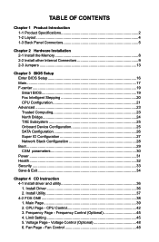
... (Optional 45 4. CPU Control 42 3. Limit Setting 45 5. Table of Contents Chapter 1 Product Introduction 1-1 Product Specifications 2 1-2 Layout...4 1-3 Back Panel Connectors 5 Chapter 2 Hardware Installation 2-1 Install the Memory 8 2-2 Install other Internal Connectors 9 2-3 Jumpers 13 Chapter 3 BIOS Setup Enter BIOS Setup 16 Main...17 F-center...19 Smart BIOS 19 Fox Intelligent Stepping 20 CPU...
... (Optional 45 4. CPU Control 42 3. Limit Setting 45 5. Table of Contents Chapter 1 Product Introduction 1-1 Product Specifications 2 1-2 Layout...4 1-3 Back Panel Connectors 5 Chapter 2 Hardware Installation 2-1 Install the Memory 8 2-2 Install other Internal Connectors 9 2-3 Jumpers 13 Chapter 3 BIOS Setup Enter BIOS Setup 16 Main...17 F-center...19 Smart BIOS 19 Fox Intelligent Stepping 20 CPU...
User Manual
Page 9
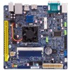
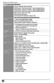
PRODUCT INTRODUCTION 1-1 Product Specifications CPU Support Intel® Bay Trail-D processor Intel® Celeron Dual-Core proessor J1800 (D180S/D180S-D) Intel® Celeron Quad-Core proessor J1900 (D190S/D190S-D) Intel® Pentium Quad-Core proessor J2900 (D290S/D290S-D) Max ...to 10W 22nm process technology For the latest CPU information, please visit: http://www.foxconnsupport.com/cpusupportlist.aspx Memory 1 x 204-pin SO-DDR3/DDR3L DIMM Support up to 8GB of system memory Support DDR3L /DDR3 1333MHz architecture Expansion Slots 1 x PCI Express X16 slot (Run PCI-E X1 Mode) ...
PRODUCT INTRODUCTION 1-1 Product Specifications CPU Support Intel® Bay Trail-D processor Intel® Celeron Dual-Core proessor J1800 (D180S/D180S-D) Intel® Celeron Quad-Core proessor J1900 (D190S/D190S-D) Intel® Pentium Quad-Core proessor J2900 (D290S/D290S-D) Max ...to 10W 22nm process technology For the latest CPU information, please visit: http://www.foxconnsupport.com/cpusupportlist.aspx Memory 1 x 204-pin SO-DDR3/DDR3L DIMM Support up to 8GB of system memory Support DDR3L /DDR3 1333MHz architecture Expansion Slots 1 x PCI Express X16 slot (Run PCI-E X1 Mode) ...
User Manual
Page 14
This chapter includes the following information : ■ Install the Memory ■ Install other Internal Connectors ■ Jumpers Caution should be exercised during the installation of jumpers. Chapter 2 Hardware Installation This chapter introduces the hardware installation process, including memory, slots, pin headers and the mounting of these modules. Please refer to the motherboard layout prior to any installation and read the contents in this chapter carefully.
This chapter includes the following information : ■ Install the Memory ■ Install other Internal Connectors ■ Jumpers Caution should be exercised during the installation of jumpers. Chapter 2 Hardware Installation This chapter introduces the hardware installation process, including memory, slots, pin headers and the mounting of these modules. Please refer to the motherboard layout prior to any installation and read the contents in this chapter carefully.
User Manual
Page 15
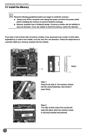
...Step 1: Plug the pin side of the memory module into the sockets. 204-Pin HARDWARE INSTALLATION 2-1 Install the Memory Read the following guidelines before installing the memory to prevent hardware damage. ■ Memory modules have a foolproof design. If you begin to install the memory : ■ Always turn off the computer...unplug the power cord from the power outlet before you are unable to insert the memory, switch the direction. Step 2: The clips at front side of the socket will snap into place when the memory moule is securely inserted and pressed. 8 If you take a look at both ...
...Step 1: Plug the pin side of the memory module into the sockets. 204-Pin HARDWARE INSTALLATION 2-1 Install the Memory Read the following guidelines before installing the memory to prevent hardware damage. ■ Memory modules have a foolproof design. If you begin to install the memory : ■ Always turn off the computer...unplug the power cord from the power outlet before you are unable to insert the memory, switch the direction. Step 2: The clips at front side of the socket will snap into place when the memory moule is securely inserted and pressed. 8 If you take a look at both ...
User Manual
Page 23
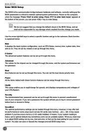
... this menu, and the system performance can be viewed or set up through this menu. However, it may cause problem if you have more memory or I /O cards, less memory ...etc.), still, it may sometimes come out an unstable system. It means, if your CPU/System. Use the arrow right/left keys to... and software, correctly setting up the BIOS parameters is heavy, set to optimal default may offer better performance in some ways (such as CPU Name, memory size, system date, time and so on the computer, when the message "Press to enter setup, Press to enter boot menu" appears at the bottom...
... this menu, and the system performance can be viewed or set up through this menu. However, it may cause problem if you have more memory or I /O cards, less memory ...etc.), still, it may sometimes come out an unstable system. It means, if your CPU/System. Use the arrow right/left keys to... and software, correctly setting up the BIOS parameters is heavy, set to optimal default may offer better performance in some ways (such as CPU Name, memory size, system date, time and so on the computer, when the message "Press to enter setup, Press to enter boot menu" appears at the bottom...

User Manual
Page 24
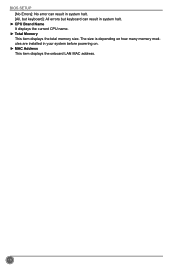
... BIOS Version Build Date and Time Halt On CPU Brand Name: Intel(R) Celeron(R) CPU J1900 @ 1.99GHz Total Memory MAC Address Power Health Security Save&Exit [Sun 09/01/2013] [00:03:38] Administrator D180S/D190S/D290S Series 01.00.02.1060 DB1F1D03 x64 12/24/2013 11:45:02 Set the Date...
... BIOS Version Build Date and Time Halt On CPU Brand Name: Intel(R) Celeron(R) CPU J1900 @ 1.99GHz Total Memory MAC Address Power Health Security Save&Exit [Sun 09/01/2013] [00:03:38] Administrator D180S/D190S/D290S Series 01.00.02.1060 DB1F1D03 x64 12/24/2013 11:45:02 Set the Date...
User Manual
Page 25
The size is depending on how many memory modules are installed in system halt. ► CPU Brand Name It displays the current CPU name. ► Total Memory This item displays the total memory size. BIOS SETUP [No Errors]: No error can result in system halt. [All, but keyboard]: All errors but keyboard can result in your system before powering on. ► MAC Address This item displays the onboard LAN MAC address. 18
The size is depending on how many memory modules are installed in system halt. ► CPU Brand Name It displays the current CPU name. ► Total Memory This item displays the total memory size. BIOS SETUP [No Errors]: No error can result in system halt. [All, but keyboard]: All errors but keyboard can result in your system before powering on. ► MAC Address This item displays the onboard LAN MAC address. 18
User Manual
Page 27
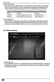
... Spread Spectrum → ←: Select Screen ↑ ↓/Click: Select Item Enter/Dbl Click: Select +/-: Change Opt. System Status Normal No Memory No Display Power LED Status Always On Continue blinking On (1sec.), Off (1sec.) Continue blinking On (2sec.), Off (2sec.) Stop Blinking Condition Always ...On Reboot & Memory OK Reboot & Display OK ► Smart Boot Menu When PC starts, it can always leave this function, it will ask you had better ...
... Spread Spectrum → ←: Select Screen ↑ ↓/Click: Select Item Enter/Dbl Click: Select +/-: Change Opt. System Status Normal No Memory No Display Power LED Status Always On Continue blinking On (1sec.), Off (1sec.) Continue blinking On (2sec.), Off (2sec.) Stop Blinking Condition Always ...On Reboot & Memory OK Reboot & Display OK ► Smart Boot Menu When PC starts, it can always leave this function, it will ask you had better ...
User Manual
Page 28
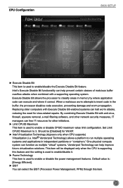
... This item is used to enable or disable CPUID maximum value limit configuration. When a malicious worm attempts to run multiple operating systems and applications in memory by where application code can select the EIST (Processor Power Management, PPM) through this feature and the setting is used to enable/disable it cannot...
... This item is used to enable or disable CPUID maximum value limit configuration. When a malicious worm attempts to run multiple operating systems and applications in memory by where application code can select the EIST (Processor Power Management, PPM) through this feature and the setting is used to enable/disable it cannot...
User Manual
Page 31
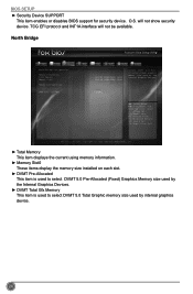
... support for security device. North Bridge Main F-center Advanced Boot Power Health Security Save&Exit North Bridge Configuration Memory Information Total Memory Memory Slot0 Memory Configuration 1024 MB (DDR3/DDR3L 1333) 1024 MB (DDR3/DDR3L 1333) DVMT Pre-Allocated DVMT Total Gfx ...Click: Select +/-: Change Opt. O.S. Copyright (C) 2013 American Megatrends, Inc. ► Total Memory This item displays the current using memory information. ► Memory Slot0 These items display the memory size installed on each slot. ► DVMT Pre-Allocated This item is used to select ...
... support for security device. North Bridge Main F-center Advanced Boot Power Health Security Save&Exit North Bridge Configuration Memory Information Total Memory Memory Slot0 Memory Configuration 1024 MB (DDR3/DDR3L 1333) 1024 MB (DDR3/DDR3L 1333) DVMT Pre-Allocated DVMT Total Gfx ...Click: Select +/-: Change Opt. O.S. Copyright (C) 2013 American Megatrends, Inc. ► Total Memory This item displays the current using memory information. ► Memory Slot0 These items display the memory size installed on each slot. ► DVMT Pre-Allocated This item is used to select ...
User Manual
Page 52
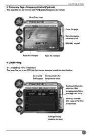
... high limit value of the CPU temperature Set high limit by manual. Limit Setting 4.1 Limit Setting - 3. page Close this page Select the option you set memory and PCI Express frequencies by dragging the lever 45 Go to set CPU high limit temperature and enable the alert function. CD INSTRUCTION Go to...
... high limit value of the CPU temperature Set high limit by manual. Limit Setting 4.1 Limit Setting - 3. page Close this page Select the option you set memory and PCI Express frequencies by dragging the lever 45 Go to set CPU high limit temperature and enable the alert function. CD INSTRUCTION Go to...
User Manual
Page 55
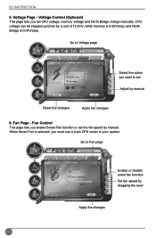
...page Enable or disable smart fan function Set fan speed by manual Reset the changes Apply the changes 6. Fan Page - Go to set CPU voltage, memory voltage and North Bridge voltage manually. Fan Control This page lets you enable Smart Fan function or set the fan speed by a unit of 12....5mV, while memory is 0.05V/step, and North Bridge is selected, you set Adjust by dragging the lever Apply the changes 48 Voltage Page - Voltage Control (Optional) ...
...page Enable or disable smart fan function Set fan speed by manual Reset the changes Apply the changes 6. Fan Page - Go to set CPU voltage, memory voltage and North Bridge voltage manually. Fan Control This page lets you enable Smart Fan function or set the fan speed by a unit of 12....5mV, while memory is 0.05V/step, and North Bridge is selected, you set Adjust by dragging the lever Apply the changes 48 Voltage Page - Voltage Control (Optional) ...
