User Manual
Page 5
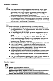
... or its components. CAUTION Installation Precautions ■ Electrostatic discharge (ESD) is the sudden and momentary electric current that the DC power supply is turned off before installing or removing CPU, memory, expansion cards or other peripherals. Incorrect connections might damage the motherboard. &#...not allow screws to come in order to avoid damage to the motherboard and CPU due to unplug the AC power cord from the power supply outlet. Technical Support Website: http://www.foxconnchannel.com Support Website: http://www.foxconnsupport.com Worldwide online contact Support:...
... or its components. CAUTION Installation Precautions ■ Electrostatic discharge (ESD) is the sudden and momentary electric current that the DC power supply is turned off before installing or removing CPU, memory, expansion cards or other peripherals. Incorrect connections might damage the motherboard. &#...not allow screws to come in order to avoid damage to the motherboard and CPU due to unplug the AC power cord from the power supply outlet. Technical Support Website: http://www.foxconnchannel.com Support Website: http://www.foxconnsupport.com Worldwide online contact Support:...
User Manual
Page 16
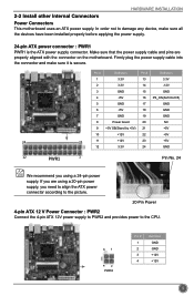
... into the connector and make sure all the devices have been installed properly before applying the power supply. 24-pin ATX power connector : PWR1 PWR1 is secure. Make sure that the power supply cable and pins are using a 24-pin power supply. Pin # Definition Pin # Definition 1 3.3V 13 3.3V 2 3.3V 14 -12V 3 GND 15 GND 4 +5V 16...
... into the connector and make sure all the devices have been installed properly before applying the power supply. 24-pin ATX power connector : PWR1 PWR1 is secure. Make sure that the power supply cable and pins are using a 24-pin power supply. Pin # Definition Pin # Definition 1 3.3V 13 3.3V 2 3.3V 14 -12V 3 GND 15 GND 4 +5V 16...
User Manual
Page 18
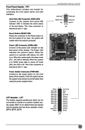
...LED is directional with +/- Push this switch allows the system to be connected to a printer or a scanner. This 2-pin connector is off. Power LED Connector (PWR-LED) Connect to the chassis front panel IDE indicator LED. sign. When the system is in operation (S0 status), the LED... and the parallel port has three operation mode: [SPP], [EPP], [ECP]. When the system is in S3/S4 sleep state or power off rather than using the power supply button. Front Panel Header : FP1 This motherboard includes one header for connecting the front panel switch and LED Indicators.
...LED is directional with +/- Push this switch allows the system to be connected to a printer or a scanner. This 2-pin connector is off. Power LED Connector (PWR-LED) Connect to the chassis front panel IDE indicator LED. sign. When the system is in operation (S0 status), the LED... and the parallel port has three operation mode: [SPP], [EPP], [ECP]. When the system is in S3/S4 sleep state or power off rather than using the power supply button. Front Panel Header : FP1 This motherboard includes one header for connecting the front panel switch and LED Indicators.


