User Manual
Page 1
D180S/D190S/D290S Series Motherboard User's Manual
D180S/D190S/D290S Series Motherboard User's Manual
User Manual
Page 2
...physical injury may not be caused by inappropriate waste handling of this product is the intellectual property of Foxconn, Inc. Symbol description: Note: Refers to the physical motherboard for the environment and human health, which could otherwise be treated as household waste. By ensuring this... is disposed of correctly, you will help you to use of this product may exist. Version: User's Manual V1.0 for D180S/D190S/D290S Series motherboard. More information: If you want more detailed information about our products, please visit: http://www.foxconnchannel.com © All rights...
...physical injury may not be caused by inappropriate waste handling of this product is the intellectual property of Foxconn, Inc. Symbol description: Note: Refers to the physical motherboard for the environment and human health, which could otherwise be treated as household waste. By ensuring this... is disposed of correctly, you will help you to use of this product may exist. Version: User's Manual V1.0 for D180S/D190S/D290S Series motherboard. More information: If you want more detailed information about our products, please visit: http://www.foxconnchannel.com © All rights...
User Manual
Page 3
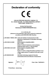
... information technology equipment ■ EN 61000-3-2/:2000 Electromagnetic compatibility (EMC) Part 3: Limits Section 2: Limits for harmonic current emissions (equipment input current declares that the product Motherboard D180S/D190S/D290S Series is in conformity with (reference to the specification under which conformity is declared in accordance with 89/336 EEC-EMC Directive) ■...
... information technology equipment ■ EN 61000-3-2/:2000 Electromagnetic compatibility (EMC) Part 3: Limits Section 2: Limits for harmonic current emissions (equipment input current declares that the product Motherboard D180S/D190S/D290S Series is in conformity with (reference to the specification under which conformity is declared in accordance with 89/336 EEC-EMC Directive) ■...
User Manual
Page 4
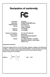
Operation is subject to comply with Part 15 of the FCC Rules. Declaration of Product: Manufacturer: Address: FCC Class B Subassembly Motherboard HON HAI PRECISION INDUSTRY COMPANY LTD 66 , CHUNG SHAN RD., TU-CHENG INDUSTRIAL DISTRICT, TAIPEI HSIEN, TAIWAN, R.O.C. Tested to the... 714-738-8868 714-738-8838 Equipment Classification: Type of conformity Trade Name: Model Name: Responsible Party: Address: Telephone: Facsimile: FOXCONN D180S/D190S/D290S Series PCE Industry Inc. 458 E. Supplementary Information: This device complies with FCC standards. Lambert Rd.
Operation is subject to comply with Part 15 of the FCC Rules. Declaration of Product: Manufacturer: Address: FCC Class B Subassembly Motherboard HON HAI PRECISION INDUSTRY COMPANY LTD 66 , CHUNG SHAN RD., TU-CHENG INDUSTRIAL DISTRICT, TAIPEI HSIEN, TAIWAN, R.O.C. Tested to the... 714-738-8868 714-738-8838 Equipment Classification: Type of conformity Trade Name: Model Name: Responsible Party: Address: Telephone: Facsimile: FOXCONN D180S/D190S/D290S Series PCE Industry Inc. 458 E. Supplementary Information: This device complies with FCC standards. Lambert Rd.
User Manual
Page 5
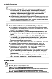
... (ESD) is turned off before installing or removing CPU, memory, expansion cards or other peripherals. Normal operation depends on the motherboard. Please wear an electrostatic discharge (ESD) wrist strap when handling components such as a spark which will quickly damage your CPU ...■ We cannot guarantee that flows between two objects at different electrical potentials. Incorrect connections might damage the motherboard. ■ When handling the motherboard, avoid touching any installation steps or have a problem related to high temperature. It is suggested to select high...
... (ESD) is turned off before installing or removing CPU, memory, expansion cards or other peripherals. Normal operation depends on the motherboard. Please wear an electrostatic discharge (ESD) wrist strap when handling components such as a spark which will quickly damage your CPU ...■ We cannot guarantee that flows between two objects at different electrical potentials. Incorrect connections might damage the motherboard. ■ When handling the motherboard, avoid touching any installation steps or have a problem related to high temperature. It is suggested to select high...
User Manual
Page 8
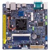
Chapter 1 Product Introduction Thank you need for buying Foxconn D180S/D190S/D290S Series motherboard. Foxconn products are engineered to maximize computing power, providing only what you for break-through performance. This chapter includes the following information: ■ Product Specifications ■ Layout ■ Back Panel Connectors
Chapter 1 Product Introduction Thank you need for buying Foxconn D180S/D190S/D290S Series motherboard. Foxconn products are engineered to maximize computing power, providing only what you for break-through performance. This chapter includes the following information: ■ Product Specifications ■ Layout ■ Back Panel Connectors
User Manual
Page 11
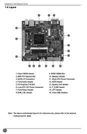
Front Panel Header 8. Front USB Headers Note : The above motherboard layout is for reference only, please refer to the physical motherboard for detail. 4 SATA 2.0 Connectors 4. PCI Express X16 Slot 6. 4-pin ATX 12V Power Connector 7. DDR3 DIMM Slot 10. Clear CMOS Header 2. Front Audio Header 5. DDR_VSL Header 9. System_Fan Header 14. LPT Header 16. F_COM Header 15. Speaker Header 11. 24-pin ATX Power Connector 12. INTR Header 13. PRODUCT INTRODUCTION 1-2 Layout 3 2 1 4 16 5 15 14 13 6 7 8 9 10 11 12 1. MINI PCI Express Slot 3.
Front Panel Header 8. Front USB Headers Note : The above motherboard layout is for reference only, please refer to the physical motherboard for detail. 4 SATA 2.0 Connectors 4. PCI Express X16 Slot 6. 4-pin ATX 12V Power Connector 7. DDR3 DIMM Slot 10. Clear CMOS Header 2. Front Audio Header 5. DDR_VSL Header 9. System_Fan Header 14. LPT Header 16. F_COM Header 15. Speaker Header 11. 24-pin ATX Power Connector 12. INTR Header 13. PRODUCT INTRODUCTION 1-2 Layout 3 2 1 4 16 5 15 14 13 6 7 8 9 10 11 12 1. MINI PCI Express Slot 3.
User Manual
Page 14
Caution should be exercised during the installation of jumpers. Please refer to the motherboard layout prior to any installation and read the contents in this chapter carefully. Chapter 2 Hardware Installation This chapter introduces the hardware installation process, including memory, slots, pin headers and the mounting of these modules. This chapter includes the following information : ■ Install the Memory ■ Install other Internal Connectors ■ Jumpers
Caution should be exercised during the installation of jumpers. Please refer to the motherboard layout prior to any installation and read the contents in this chapter carefully. Chapter 2 Hardware Installation This chapter introduces the hardware installation process, including memory, slots, pin headers and the mounting of these modules. This chapter includes the following information : ■ Install the Memory ■ Install other Internal Connectors ■ Jumpers
User Manual
Page 16
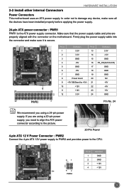
... 3.3V 24 GND 12 PWR1 1 Pin No. 24 We recommend you using a 20-pin power supply, you are properly aligned with the connector on the motherboard. If you need to align the ATX power connector according to the picture. 20-Pin Power 4-pin ATX 12 V Power Connector : PWR2 Connect the 4-pin... supply. In order not to the CPU. 31 42 PWR2 Pin # 1 2 3 4 Definition GND GND +12V +12V 9 HARDWARE INSTALLATION 2-2 Install other Internal Connectors Power Connectors This motherboard uses an ATX power supply.
... 3.3V 24 GND 12 PWR1 1 Pin No. 24 We recommend you using a 20-pin power supply, you are properly aligned with the connector on the motherboard. If you need to align the ATX power connector according to the picture. 20-Pin Power 4-pin ATX 12 V Power Connector : PWR2 Connect the 4-pin... supply. In order not to the CPU. 31 42 PWR2 Pin # 1 2 3 4 Definition GND GND +12V +12V 9 HARDWARE INSTALLATION 2-2 Install other Internal Connectors Power Connectors This motherboard uses an ATX power supply.
User Manual
Page 18
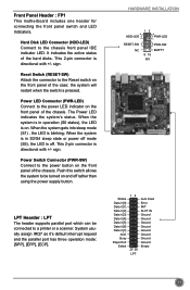
... Connector (PWR-SW) Connect to the chassis front panel IDE indicator LED. It indicates the active status of the chassis. Front Panel Header : FP1 This motherboard includes one header for connecting the front panel switch and LED Indicators. Hard Disk LED Connector (HDD-LED) Connect to the power button on the...
... Connector (PWR-SW) Connect to the chassis front panel IDE indicator LED. It indicates the active status of the chassis. Front Panel Header : FP1 This motherboard includes one header for connecting the front panel switch and LED Indicators. Hard Disk LED Connector (HDD-LED) Connect to the power button on the...
User Manual
Page 19
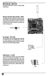
...automatically turned off after the system enters S3, S4 and S5 sleeping states. 1 GND POWER SENSE CONTROL SYS_FAN COM Header : F_COM This motherboard supports one end to connect with the external RS232 device and another end with 10-pin female connector to a security switch on the chassis.... INTRUDERJ 1 GND INTR Fan Header : SYS_FAN The fan speed can be controlled and monitored in the motherboard. The system can be connected to connect with a 9-pin D-sub connector at one serial RS232 COM port for legacy compatibility. User must purchase...
...automatically turned off after the system enters S3, S4 and S5 sleeping states. 1 GND POWER SENSE CONTROL SYS_FAN COM Header : F_COM This motherboard supports one end to connect with the external RS232 device and another end with 10-pin female connector to a security switch on the chassis.... INTRUDERJ 1 GND INTR Fan Header : SYS_FAN The fan speed can be controlled and monitored in the motherboard. The system can be connected to connect with a 9-pin D-sub connector at one serial RS232 COM port for legacy compatibility. User must purchase...
User Manual
Page 20
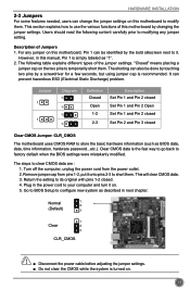
... The shorting can also be identified by the bold silkscreen next to it onto pins 2-3 to your computer and turn it on this motherboard by a screwdriver for a few seconds, but using jumper cap is simply labeled as BIOS data, date, time information, hardware password...etc.).... Description of this motherboard to its original with pins 1-2 closed Clear CMOS Jumper: CLR_CMOS The motherboard uses CMOS RAM to modifying any jumper on this manual, Pin 1 is recommended. The steps to factory...
... The shorting can also be identified by the bold silkscreen next to it onto pins 2-3 to your computer and turn it on this motherboard by a screwdriver for a few seconds, but using jumper cap is simply labeled as BIOS data, date, time information, hardware password...etc.).... Description of this motherboard to its original with pins 1-2 closed Clear CMOS Jumper: CLR_CMOS The motherboard uses CMOS RAM to modifying any jumper on this manual, Pin 1 is recommended. The steps to factory...
User Manual
Page 21
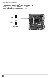
HARDWARE INSTALLATION Voltage DDR Select Header: DDR_VSL This motherboard uses this jumper to select the voltage for DDR. Set the jumper to pins 2-3, the DDR3 Power is 1.35V. Set the jumper to pins 1-2, the DDR3 Power is 1.5V. 1 1.35V 2 3 1 1.5V 2 3 DDR_VSL 14
HARDWARE INSTALLATION Voltage DDR Select Header: DDR_VSL This motherboard uses this jumper to select the voltage for DDR. Set the jumper to pins 2-3, the DDR3 Power is 1.35V. Set the jumper to pins 1-2, the DDR3 Power is 1.5V. 1 1.35V 2 3 1 1.5V 2 3 DDR_VSL 14
User Manual
Page 27
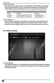
... Version 2.16.1242. The LED is located at the front panel, and it . 20 This also prevents user without password trying to get into your motherboard to comply with FCC regulation. But if overclocking is selected, then pressing [F7] has no function.
... Version 2.16.1242. The LED is located at the front panel, and it . 20 This also prevents user without password trying to get into your motherboard to comply with FCC regulation. But if overclocking is selected, then pressing [F7] has no function.

User Manual
Page 29
... Intel SpeedStep® technology (EIST) allows the system to select the C-State mode. 22 There are some system requirements must be met, including CPU, chipset, motherboard, BIOS and operation system. Please refer to Intel Website for more information. ► CPU C3 Report This item is used to enable or disable CPU...
... Intel SpeedStep® technology (EIST) allows the system to select the C-State mode. 22 There are some system requirements must be met, including CPU, chipset, motherboard, BIOS and operation system. Please refer to Intel Website for more information. ► CPU C3 Report This item is used to enable or disable CPU...

User Manual
Page 33
... Host Controller Interface (AHCI) specification describes the register level interface for a Host Controller for USB devices on legacy OS. The specification includes a description of your motherboard supporting AHCI, and you have a SATA device, which also supports AHCI, then you can select AHCI to get its specification. If your SATA ports. [Native...
... Host Controller Interface (AHCI) specification describes the register level interface for a Host Controller for USB devices on legacy OS. The specification includes a description of your motherboard supporting AHCI, and you have a SATA device, which also supports AHCI, then you can select AHCI to get its specification. If your SATA ports. [Native...
User Manual
Page 38
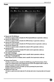
F1: General Help F2: Previous Values F3: Optimized Defaults F4: Save & Exit ESC/Right Click: Exit Version 2.16.1242. When enable, the suspend power of motherboard. Disabled: Normal ACPI function. ► Restore AC Power Loss This item is used to enable or disable the EuP(Energy-using Products) feature. RTC is ...
F1: General Help F2: Previous Values F3: Optimized Defaults F4: Save & Exit ESC/Right Click: Exit Version 2.16.1242. When enable, the suspend power of motherboard. Disabled: Normal ACPI function. ► Restore AC Power Loss This item is used to enable or disable the EuP(Energy-using Products) feature. RTC is ...
User Manual
Page 41
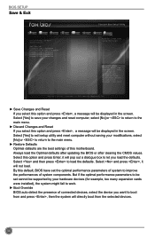
... Restore Defaults Optimal defaults are the best settings of connected devices, select the device you want to let you select this motherboard. Select [Yes] to exit setup utility and reset computer without saving your hardware devices (for example, too many expansion ... Advanced Boot Save Changes and Reset Discard Changes and Reset Restore Defaults Boot Override Foxconn MS USB2.0 Reade9144 UEFI: Foxconn MS USB2.0 Reade9144 Foxconn CF USB2.0 Reade9144 Foxconn SM USB2.0 Reade9144 Foxconn SD USB2.0 Reade9144 Power Health Security Save&Exit Reset the system after clearing the...
... Restore Defaults Optimal defaults are the best settings of connected devices, select the device you want to let you select this motherboard. Select [Yes] to exit setup utility and reset computer without saving your hardware devices (for example, too many expansion ... Advanced Boot Save Changes and Reset Discard Changes and Reset Restore Defaults Boot Override Foxconn MS USB2.0 Reade9144 UEFI: Foxconn MS USB2.0 Reade9144 Foxconn CF USB2.0 Reade9144 Foxconn SM USB2.0 Reade9144 Foxconn SD USB2.0 Reade9144 Power Health Security Save&Exit Reset the system after clearing the...
User Manual
Page 42
This chapter includes the following information: ■ Install driver and utility ■ FOX ONE ■ FOX LiveUpdate ■ FOX LOGO ■ AMI DMI Chapter 4 CD Instruction The utility CD that comes with the motherboard contains useful software and several utility drivers that enhance the motherboard features.
This chapter includes the following information: ■ Install driver and utility ■ FOX ONE ■ FOX LiveUpdate ■ FOX LOGO ■ AMI DMI Chapter 4 CD Instruction The utility CD that comes with the motherboard contains useful software and several utility drivers that enhance the motherboard features.
User Manual
Page 44
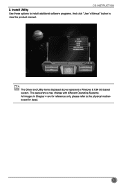
Install Utility Use these options to install additional software programs. And click "User's Manual" button to the physical motherboard for detail. 37 The Driver and Utility items displayed above represent a Windows 8.1(64 bit) based system. The appearance may change with different Operating Systems. All images in Chapter 4 are for reference only, please refer to view the product manual. CD INSTRUCTION 2.
Install Utility Use these options to install additional software programs. And click "User's Manual" button to the physical motherboard for detail. 37 The Driver and Utility items displayed above represent a Windows 8.1(64 bit) based system. The appearance may change with different Operating Systems. All images in Chapter 4 are for reference only, please refer to view the product manual. CD INSTRUCTION 2.


