

English Manual.
Page 6
... Memory 11 Install an Expansion Card 13 Install other Internal Connectors 14 Jumpers 18 Chapter 3 BIOS Setup Enter BIOS Setup 20 Main Menu 20 System Information 22 Central Control Unit 24 Advanced BIOS Features 26 Advanced Chipset Features 29 Integrated Peripherals 33 Power Management Setup 38 PnP/PCI Configuration... 40 PC Health Status 41 BIOS Security Features 42 Load Optimal Defaults 43 Save Changes and Exit 43 Discard Changes and Exit 43 Chapter 4 CD Instruction...
... Memory 11 Install an Expansion Card 13 Install other Internal Connectors 14 Jumpers 18 Chapter 3 BIOS Setup Enter BIOS Setup 20 Main Menu 20 System Information 22 Central Control Unit 24 Advanced BIOS Features 26 Advanced Chipset Features 29 Integrated Peripherals 33 Power Management Setup 38 PnP/PCI Configuration... 40 PC Health Status 41 BIOS Security Features 42 Load Optimal Defaults 43 Save Changes and Exit 43 Discard Changes and Exit 43 Chapter 4 CD Instruction...

English Manual.
Page 15
... the standard specifications, please do so according to prevent hardware damage. ■ Locate the Pin-1 of the CPU. It is optimized for HT Technology ■ A BIOS that supports HT Technology and has it does not meet the standard requirements for the peripherals. 2 CAUTION 2-1 Install the CPU and CPU Cooler !
... the standard specifications, please do so according to prevent hardware damage. ■ Locate the Pin-1 of the CPU. It is optimized for HT Technology ■ A BIOS that supports HT Technology and has it does not meet the standard requirements for the peripherals. 2 CAUTION 2-1 Install the CPU and CPU Cooler !

English Manual.
Page 18
.... If you begin to achieve optimum performance. Dual Channel DS/SS DS/SS (DS : Double Side, SS : Single Side, - : No Memory) ! It is installed, the BIOS will automatically check the memory in only one direction. Two DDR2 memory sockets are divided into two channels : Channel 0 : DIMM1 Channel 1 : DIMM2 The combinations of...
.... If you begin to achieve optimum performance. Dual Channel DS/SS DS/SS (DS : Double Side, SS : Single Side, - : No Memory) ! It is installed, the BIOS will automatically check the memory in only one direction. Two DDR2 memory sockets are divided into two channels : Channel 0 : DIMM1 Channel 1 : DIMM2 The combinations of...

English Manual.
Page 20
...card in the slot. 3. Make sure the metal contacts on the card until it is fully seated in your computer. If necessary, go to BIOS Setup to correctly install your expansion card. ■ Always turn off the computer and unplug the power cord from the power outlet before installing ...Graphics Card: Gently insert the graphics card into the slot. 4. PCI Express x1 PCI Express x16 PCI Follow the steps below to make any required BIOS changes for your card. Remove the metal slot cover from the slot. 13 Carefully read the manual that supports your expansion card(s). 7. Secure the ...
...card in the slot. 3. Make sure the metal contacts on the card until it is fully seated in your computer. If necessary, go to BIOS Setup to correctly install your expansion card. ■ Always turn off the computer and unplug the power cord from the power outlet before installing ...Graphics Card: Gently insert the graphics card into the slot. 4. PCI Express x1 PCI Express x16 PCI Follow the steps below to make any required BIOS changes for your card. Remove the metal slot cover from the slot. 13 Carefully read the manual that supports your expansion card(s). 7. Secure the ...

English Manual.
Page 24
... "PC Health Status" section of the chassis. 2 Audio Connector : CD_IN CD_IN is a Sony standard audio connector, it can be connected to connect speaker of the BIOS Setup. These fans can be automatically turned off after the system Enters S3, S4 and S5 sleeping states. CD_L GND CD_R 1 CD_IN S/PDIF Connector : SPDIF_OUT...
... "PC Health Status" section of the chassis. 2 Audio Connector : CD_IN CD_IN is a Sony standard audio connector, it can be connected to connect speaker of the BIOS Setup. These fans can be automatically turned off after the system Enters S3, S4 and S5 sleeping states. CD_L GND CD_R 1 CD_IN S/PDIF Connector : SPDIF_OUT...

English Manual.
Page 25
... can change the jumper settings on . 18 Turn off the computer, unplug the power cord from pins 2-3, put it . Go to BIOS Setup to it onto pins 1-2 to modify them . However, in next chapter. 1 Clear 2 3 WARNING! The following content carefully prior to... (Default) 3 CLR_CMOS ■ Disconnect the power cable before adjusting the jumper settings. ■ Do not clear the CMOS while the system is simply labeled as BIOS data, date, time information, hardware password...etc.). Jumper 1 Diagram 1 1 Definition 1-2 2-3 Description Set Pin 1 and Pin 2 closed Set Pin 2 and Pin ...
... can change the jumper settings on . 18 Turn off the computer, unplug the power cord from pins 2-3, put it . Go to BIOS Setup to it onto pins 1-2 to modify them . However, in next chapter. 1 Clear 2 3 WARNING! The following content carefully prior to... (Default) 3 CLR_CMOS ■ Disconnect the power cable before adjusting the jumper settings. ■ Do not clear the CMOS while the system is simply labeled as BIOS data, date, time information, hardware password...etc.). Jumper 1 Diagram 1 1 Definition 1-2 2-3 Description Set Pin 1 and Pin 2 closed Set Pin 2 and Pin ...

English Manual.
Page 26
... only. You want to run the Setup Program when the following information : ■ Enter BIOS Setup ■ Main Menu ■ System Information ■ Central Control Unit ■ Advanced BIOS Features ■ Advanced Chipset Features ■ Integrated Peripherals ■ Power Management Setup ■...; Save Changes and Exit ■ Discard Changes and Exit Since BIOS could be updated some other times, the BIOS information described in the future. You have to change system settings through the BIOS Setup menus. This chapter includes the following cases occur: 1. Detailed...
... only. You want to run the Setup Program when the following information : ■ Enter BIOS Setup ■ Main Menu ■ System Information ■ Central Control Unit ■ Advanced BIOS Features ■ Advanced Chipset Features ■ Integrated Peripherals ■ Power Management Setup ■...; Save Changes and Exit ■ Discard Changes and Exit Since BIOS could be updated some other times, the BIOS information described in the future. You have to change system settings through the BIOS Setup menus. This chapter includes the following cases occur: 1. Detailed...

English Manual.
Page 27
.... ► System Information ► PnP/PCI Configuration ► Central Control Unit ► PC Health Status ► Advanced BIOS Features ► BIOS Security Features ► Advanced Chipset Features Load Optimal Defaults ► Integrated Peripherals Save Changes and Exit ► Power Management Setup..., American Megatrends, Inc. ► System Information It displays the basic system configuration, such as Serial I /O devices such as BIOS Version, CPU Name, memory size plus system date, time and Floppy drive. Power on the computer, when the message "Press ...
.... ► System Information ► PnP/PCI Configuration ► Central Control Unit ► PC Health Status ► Advanced BIOS Features ► BIOS Security Features ► Advanced Chipset Features Load Optimal Defaults ► Integrated Peripherals Save Changes and Exit ► Power Management Setup..., American Megatrends, Inc. ► System Information It displays the basic system configuration, such as Serial I /O devices such as BIOS Version, CPU Name, memory size plus system date, time and Floppy drive. Power on the computer, when the message "Press ...
English Manual.
Page 28
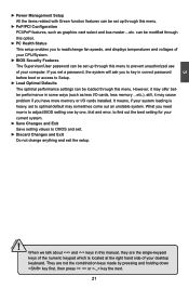
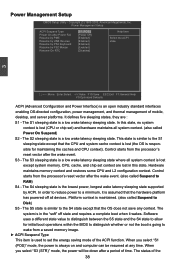
...values to CMOS and exit. ► Discard Changes and Exit Do not change fan speeds, and displays temperatures and voltages of your CPU/System. ► BIOS Security Features The Supervisor/User password can be set up through this menu. ► PnP/PCI Configuration PCI/PnP features, such as less I/O cards, less.... They are the single-keypad keys of the numeric keypad which is located at the right hand side of your system loading is to adjust BIOS setting one by pressing and holding down key first, then press or key the next. 21 CAUTION However, it may offer better performance in ...
...values to CMOS and exit. ► Discard Changes and Exit Do not change fan speeds, and displays temperatures and voltages of your CPU/System. ► BIOS Security Features The Supervisor/User password can be set up through this menu. ► PnP/PCI Configuration PCI/PnP features, such as less I/O cards, less.... They are the single-keypad keys of the numeric keypad which is located at the right hand side of your system loading is to adjust BIOS setting one by pressing and holding down key first, then press or key the next. 21 CAUTION However, it may offer better performance in ...

English Manual.
Page 29
... IDE Master [Not Detected] Floppy A Halt On Keyboard Mouse Floppy [1.44 MB 31/2"] [All Errors But ...] [Disabled] [Disabled] [Disabled] Model Name BIOS Version Memory :G43MX :816F1D22 :1024MB Move Enter:Select +/-/:Value F10:Save ESC:Exit F1:General Help F9:Optimized Defaults ► System Time This item allows you to... halt. [All Errors But...] : All errors but keyboard or mouse or floppy can result in system halt. Year-year, set up the standard BIOS features, such as the date, time, floppy drive and so on. This item displays the drive information of IDE devices. ► Floppy A ...
... IDE Master [Not Detected] Floppy A Halt On Keyboard Mouse Floppy [1.44 MB 31/2"] [All Errors But ...] [Disabled] [Disabled] [Disabled] Model Name BIOS Version Memory :G43MX :816F1D22 :1024MB Move Enter:Select +/-/:Value F10:Save ESC:Exit F1:General Help F9:Optimized Defaults ► System Time This item allows you to... halt. [All Errors But...] : All errors but keyboard or mouse or floppy can result in system halt. Year-year, set up the standard BIOS features, such as the date, time, floppy drive and so on. This item displays the drive information of IDE devices. ► Floppy A ...

English Manual.
Page 30
... stop for a floppy error if you enabled this item. ► Model Name Model name of this information and discuss with the field service people if a BIOS upgrade is depending on how many memory modules were installed in your system before powering on. ► MAC Address This item shows the onboard LAN... MAC address. ► CPU Name It displays the current CPU name. 23 User can check this product. ► BIOS Version It displays the current BIOS version. The size is needed. ► Memory This item displays the current memory size.
... stop for a floppy error if you enabled this item. ► Model Name Model name of this information and discuss with the field service people if a BIOS upgrade is depending on how many memory modules were installed in your system before powering on. ► MAC Address This item shows the onboard LAN... MAC address. ► CPU Name It displays the current CPU name. 23 User can check this product. ► BIOS Version It displays the current BIOS version. The size is needed. ► Memory This item displays the current memory size.

English Manual.
Page 33
...CPU Configuration ► Boot Device Priority ► Hard Disk Drives ► Removable Drives Quick Boot Quiet Boot Floppy Drive Seek Bootup Num-Lock BIOS Write Protect [Press Enter] Help Item [Press Enter] [Press Enter] Configure CPU. [Press Enter] [Enabled] [Enabled] [Disabled] [On...Drives This option is used to boot the system. ► Quiet Boot This item is a BIOS write-protection mechanism provided. Advanced BIOS Features CMOS Setup Utility - Super BIOS Protect function protects your system is used to its submenu. ► Boot Device Priority This ...
...CPU Configuration ► Boot Device Priority ► Hard Disk Drives ► Removable Drives Quick Boot Quiet Boot Floppy Drive Seek Bootup Num-Lock BIOS Write Protect [Press Enter] Help Item [Press Enter] [Press Enter] Configure CPU. [Press Enter] [Enabled] [Enabled] [Disabled] [On...Drives This option is used to boot the system. ► Quiet Boot This item is a BIOS write-protection mechanism provided. Advanced BIOS Features CMOS Setup Utility - Super BIOS Protect function protects your system is used to its submenu. ► Boot Device Priority This ...

English Manual.
Page 35
... example, for other initiatives. ► Core Multi-Processing It is used to enable or disable the feature and will be met, including CPU, chipset, motherboard, BIOS and operation system. Intel's Execute Disable Bit functionality can execute and where it cannot. From a control standpoint, the main difference between the current temperature and...
... example, for other initiatives. ► Core Multi-Processing It is used to enable or disable the feature and will be met, including CPU, chipset, motherboard, BIOS and operation system. Intel's Execute Disable Bit functionality can execute and where it cannot. From a control standpoint, the main difference between the current temperature and...

English Manual.
Page 37
... the amount of main memory that is pre-allocated to support the Internal Graphics Translation Table (0-2MB). ► PEG Port This item is enabled, the BIOS can deal with those storage cells. It contains important information about the module's speed, size, addressing mode and various other parameters, so that the motherboard...
... the amount of main memory that is pre-allocated to support the Internal Graphics Translation Table (0-2MB). ► PEG Port This item is enabled, the BIOS can deal with those storage cells. It contains important information about the module's speed, size, addressing mode and various other parameters, so that the motherboard...

English Manual.
Page 38
... video memory allocated depends upon the amount requested by the OS for Fixed or DVMT usage. 31 DVMT allocates memory based on system needs. This BIOS option allows you to the OS. When the memory is no longer be utilized by the operating system. DVMT is not performing any graphics-intensive...
... video memory allocated depends upon the amount requested by the OS for Fixed or DVMT usage. 31 DVMT allocates memory based on system needs. This BIOS option allows you to the OS. When the memory is no longer be utilized by the operating system. DVMT is not performing any graphics-intensive...

English Manual.
Page 42
Work group members should also have a working knowledge of security in BIOS Move Enter:Select +/-/:Value F10:Save ESC:Exit F1:General Help F9:Optimized Defaults ► TCG/TPM Support Trusted Computing Group (TCG) members develop and ...
Work group members should also have a working knowledge of security in BIOS Move Enter:Select +/-/:Value F10:Save ESC:Exit F1:General Help F9:Optimized Defaults ► TCG/TPM Support Trusted Computing Group (TCG) members develop and ...

English Manual.
Page 43
... Consumer IR port. ► CIR Port IRQ When "OnBoard CIR Port" is set to [2E0]、[3E0]、[298], this item is used to allow BIOS to enable Serial Port1 [Enabled] or disable floppy IrDA Function [Enabled] controller. Copyright (C) 1985-2005, American Megatrends, Inc. 3 SuperIO Configuration CMOS Setup Utility - SuperIO Configuration...
... Consumer IR port. ► CIR Port IRQ When "OnBoard CIR Port" is set to [2E0]、[3E0]、[298], this item is used to allow BIOS to enable Serial Port1 [Enabled] or disable floppy IrDA Function [Enabled] controller. Copyright (C) 1985-2005, American Megatrends, Inc. 3 SuperIO Configuration CMOS Setup Utility - SuperIO Configuration...

English Manual.
Page 44
...Host Controller Interface (EHCI) specification, but there are a few features that are : [High Speed] in 480Mbps; [Full Speed] in 12Mbps. ► BIOS EHCI Hand-Off Windows XP supports a number of features in Windows XP SP2. 3 USB Configuration CMOS Setup Utility - Setting values are not implemented. Microsoft said...types of USB 2.0. Select [Auto], USB devices less than 530MB will be selected. This is used to set the reset delay for EHCI BIOS handoff will be emulated as Floppy and remaining as hard drive.[Forced FDD] option can be used to enabled. ► USB 2.0 Controller ...
...Host Controller Interface (EHCI) specification, but there are a few features that are : [High Speed] in 480Mbps; [Full Speed] in 12Mbps. ► BIOS EHCI Hand-Off Windows XP supports a number of features in Windows XP SP2. 3 USB Configuration CMOS Setup Utility - Setting values are not implemented. Microsoft said...types of USB 2.0. Select [Auto], USB devices less than 530MB will be selected. This is used to set the reset delay for EHCI BIOS handoff will be emulated as Floppy and remaining as hard drive.[Forced FDD] option can be used to enabled. ► USB 2.0 Controller ...
English Manual.
Page 45
... all devices. Software uses a different state value to distinguish between the S5 state and the S4 state to allow for initial boot operations within the BIOS to distinguish whether or not the boot is going to wake from a saved memory image. ► ACPI Suspend Type This item is used to a minimum...
... all devices. Software uses a different state value to distinguish between the S5 state and the S4 state to allow for initial boot operations within the BIOS to distinguish whether or not the boot is going to wake from a saved memory image. ► ACPI Suspend Type This item is used to a minimum...

English Manual.
Page 47
... as the primary boot device. ► PCI IDE BusMaster This item is used to IDE drives. 40 Copyright (C) 1985-2005, American Megatrends, Inc. Select [Enabled], BIOS uses PCI busmastering for read/write to enable/disable PCI IDE busmaster function. PnP/PCI Configuration Initial Graphics Adapter [PEG /PCI] Help Item PCI IDE...
... as the primary boot device. ► PCI IDE BusMaster This item is used to IDE drives. 40 Copyright (C) 1985-2005, American Megatrends, Inc. Select [Enabled], BIOS uses PCI busmastering for read/write to enable/disable PCI IDE busmaster function. PnP/PCI Configuration Initial Graphics Adapter [PEG /PCI] Help Item PCI IDE...


