
User manual
Page 1
H61S Series Motherboard User's Manual
H61S Series Motherboard User's Manual
User manual
Page 2
... household waste disposal service or the shop where you purchased this symbol indicates that can help you to the physical motherboard for H61S Series motherboard. All images are the property of their respective owners. Trademark: All trademarks are for reference only, please refer to use...damage or physical injury may be treated as household waste. By ensuring this manual may exist. All trade names are registered trademarks of Foxconn, Inc. CAUTION Statement: This manual is disposed of correctly, you how to inform the user of these changes. Although the information in...
... household waste disposal service or the shop where you purchased this symbol indicates that can help you to the physical motherboard for H61S Series motherboard. All images are the property of their respective owners. Trademark: All trademarks are for reference only, please refer to use...damage or physical injury may be treated as household waste. By ensuring this manual may exist. All trade names are registered trademarks of Foxconn, Inc. CAUTION Statement: This manual is disposed of correctly, you how to inform the user of these changes. Although the information in...

User manual
Page 3
... information technology equipment ■ EN 61000-3-2/:2000 Electromagnetic compatibility (EMC) Part 3: Limits Section 2: Limits for harmonic current emissions (equipment input current declares that the product Motherboard H61S is in conformity with (reference to the specification under which conformity is declared in accordance with 89/336 EEC-EMC Directive) ■ EN 55022:1998...
... information technology equipment ■ EN 61000-3-2/:2000 Electromagnetic compatibility (EMC) Part 3: Limits Section 2: Limits for harmonic current emissions (equipment input current declares that the product Motherboard H61S is in conformity with (reference to the specification under which conformity is declared in accordance with 89/336 EEC-EMC Directive) ■ EN 55022:1998...

User manual
Page 4
...Type of the FCC Rules. Signature : Date : 2011 Operation is subject to comply with Part 15 of Product: Manufacturer: Address: FCC Class B Subassembly Motherboard HON HAI PRECISION INDUSTRY COMPANY LTD 66 , CHUNG SHAN RD., TU-CHENG INDUSTRIAL DISTRICT, TAIPEI HSIEN, TAIWAN, R.O.C. Supplementary Information: This device complies with FCC... interference received, including interference that may cause undesired operation. Declaration of conformity Trade Name: Model Name: Responsible Party: Address: Telephone: Facsimile: FOXCONN H61S PCE Industry Inc. 458 E. Lambert Rd.
...Type of the FCC Rules. Signature : Date : 2011 Operation is subject to comply with Part 15 of Product: Manufacturer: Address: FCC Class B Subassembly Motherboard HON HAI PRECISION INDUSTRY COMPANY LTD 66 , CHUNG SHAN RD., TU-CHENG INDUSTRIAL DISTRICT, TAIPEI HSIEN, TAIWAN, R.O.C. Supplementary Information: This device complies with FCC... interference received, including interference that may cause undesired operation. Declaration of conformity Trade Name: Model Name: Responsible Party: Address: Telephone: Facsimile: FOXCONN H61S PCE Industry Inc. 458 E. Lambert Rd.

User manual
Page 5
...or removing CPU, memory, expansion cards or other peripherals. Never turn on the power, please make sure their pinouts are matching with the motherboard circuit or its components. It is any metal leads or connectors. ■ If there is a PCI Express x16 graphics card installed ...pin ATX power supply to high temperature. Please carefully read the following procedures to install your electronic equipment. Normally it comes out as a motherboard, CPU or memory. ■ Ensure that the DC power supply is the sudden and momentary electric current that your system can operate ...
...or removing CPU, memory, expansion cards or other peripherals. Never turn on the power, please make sure their pinouts are matching with the motherboard circuit or its components. It is any metal leads or connectors. ■ If there is a PCI Express x16 graphics card installed ...pin ATX power supply to high temperature. Please carefully read the following procedures to install your electronic equipment. Normally it comes out as a motherboard, CPU or memory. ■ Ensure that the DC power supply is the sudden and momentary electric current that your system can operate ...

User manual
Page 8
This chapter includes the following information: ■ Product Specifications ■ Layout ■ Back Panel Connectors Foxconn products are engineered to unleash more power from your computer. With advanced overclocking capability and a range of connectivity features for today multi-media computing requirements, H61S enables you to maximize computing power, providing only what you for break-through performance. Thank you need for buying Foxconn H61S Series motherboard.
This chapter includes the following information: ■ Product Specifications ■ Layout ■ Back Panel Connectors Foxconn products are engineered to unleash more power from your computer. With advanced overclocking capability and a range of connectivity features for today multi-media computing requirements, H61S enables you to maximize computing power, providing only what you for break-through performance. Thank you need for buying Foxconn H61S Series motherboard.
User manual
Page 10
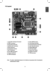
... 2. PCI Express x16 Slot 7. Front Panel Connector 13. 24-pin ATX Power Connector 14. DDR3 DIMM Slots 16. System Fan Header 18. Chipset Intel® H61 10. CPU Fan Header 17. MF G Connector 8. Clear CMOS Jumper 12. LGA 1155 CPU Socket 15. S/PDIF_OUT Connector 5. INTR Connector 6. SATA Connectors 19 18 17... 16 15 14 11. Speaker Connector 19. Front Audio Connector 4. Front USB Connectors 9. TPM Connector Note : The above motherboard layout is for reference only, please refer to the physical...
... 2. PCI Express x16 Slot 7. Front Panel Connector 13. 24-pin ATX Power Connector 14. DDR3 DIMM Slots 16. System Fan Header 18. Chipset Intel® H61 10. CPU Fan Header 17. MF G Connector 8. Clear CMOS Jumper 12. LGA 1155 CPU Socket 15. S/PDIF_OUT Connector 5. INTR Connector 6. SATA Connectors 19 18 17... 16 15 14 11. Speaker Connector 19. Front Audio Connector 4. Front USB Connectors 9. TPM Connector Note : The above motherboard layout is for reference only, please refer to the physical...

User manual
Page 13
... ■ Install an Expansion Card ■ Install other Internal Connectors ■ Jumpers Please visit the following website for more supporting information about your motherboard. Caution should be exercised during the installation of jumpers. This chapter introduces the hardware installation process, including the installation of the CPU, memory, power... supply, slots, pin headers and the mounting of these modules. Please refer to the motherboard layout prior to any installation and read the contents in this chapter carefully.
... ■ Install an Expansion Card ■ Install other Internal Connectors ■ Jumpers Please visit the following website for more supporting information about your motherboard. Caution should be exercised during the installation of jumpers. This chapter introduces the hardware installation process, including the installation of the CPU, memory, power... supply, slots, pin headers and the mounting of these modules. Please refer to the motherboard layout prior to any installation and read the contents in this chapter carefully.

User manual
Page 14
... CPU specifications. The CPU cannot be set the frequency beyond hardware specifications since it enabled Install the CPU Locate the alignment keys on the motherboard CPU socket and the notches on the CPU. Read the following guidelines before you begin to install the CPU : ■ Make sure that ...the motherboard supports the CPU. ■ Always turn on the computer if the CPU cooler is optimized for more information about the Hyper-Threading Technology) ■...
... CPU specifications. The CPU cannot be set the frequency beyond hardware specifications since it enabled Install the CPU Locate the alignment keys on the motherboard CPU socket and the notches on the CPU. Read the following guidelines before you begin to install the CPU : ■ Make sure that ...the motherboard supports the CPU. ■ Always turn on the computer if the CPU cooler is optimized for more information about the Hyper-Threading Technology) ■...

User manual
Page 16
...4-wire CPU cooler connector to its default position. ! Place the four bolts of the CPU cooler to the holes of the motherboard, push them straight down from motherboard : 1.Turning the push pin (bolt) along with the direction of CPU cooler from the top, and the bolts will be... fixed as the example.) 2 1. Turning push pin clockwise to the CPU FAN header on the motherboard. (The following procedures use Foxconn cooler as depicted in the picture. 3 2 1 4. Pull the push pin straight up. 3. Inadequately removing the CPU cooler may adhere ...
...4-wire CPU cooler connector to its default position. ! Place the four bolts of the CPU cooler to the holes of the motherboard, push them straight down from motherboard : 1.Turning the push pin (bolt) along with the direction of CPU cooler from the top, and the bolts will be... fixed as the example.) 2 1. Turning push pin clockwise to the CPU FAN header on the motherboard. (The following procedures use Foxconn cooler as depicted in the picture. 3 2 1 4. Pull the push pin straight up. 3. Inadequately removing the CPU cooler may adhere ...

User manual
Page 17
... sure that memory of the same capacity, brand, speed, and chips be installed in your system. It is recommended that the motherboard supports the memory. Dual Channel Memory Configuration This motherboard provides two DDR3 memory sockets and supports Dual Channel Technology. It is installed, the BIOS will automatically check the memory in...
... sure that memory of the same capacity, brand, speed, and chips be installed in your system. It is recommended that the motherboard supports the memory. Dual Channel Memory Configuration This motherboard provides two DDR3 memory sockets and supports Dual Channel Technology. It is installed, the BIOS will automatically check the memory in...

User manual
Page 18
Notch If you take a look at front side of memory module, it has asymmetric pin counts on this motherboard. Step 2: The clips at both sides separated by a notch in one direction. Step 1: Spread the clips at both ends of the socket will snap into ...
Notch If you take a look at front side of memory module, it has asymmetric pin counts on this motherboard. Step 2: The clips at both sides separated by a notch in one direction. Step 1: Spread the clips at both ends of the socket will snap into ...
User manual
Page 19
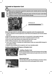
... your operating system. Turn on the card are completely inserted into the PCI Express x16 slot. 2 CAUTION 2-3 Install an Expansion Card ! ■ Make sure the motherboard supports the expansion card. Make sure the metal contacts on your expansion card. ■ Always turn off the computer and unplug the power cord from...
... your operating system. Turn on the card are completely inserted into the PCI Express x16 slot. 2 CAUTION 2-3 Install an Expansion Card ! ■ Make sure the motherboard supports the expansion card. Make sure the metal contacts on your expansion card. ■ Always turn off the computer and unplug the power cord from...

User manual
Page 20
... power supply. 24-pin ATX power connector : PWR1 PWR1 is secure. 2 2-4 Install other Internal Connectors Power Connectors This motherboard uses an ATX power supply. We recommend you are properly aligned with the connector on the motherboard. In order not to the CPU. 3 1 +12V GND 4 2 PWR2 Pin # 1 2 3 4 Definition GND GND +12V +12V 13...
... power supply. 24-pin ATX power connector : PWR1 PWR1 is secure. 2 2-4 Install other Internal Connectors Power Connectors This motherboard uses an ATX power supply. We recommend you are properly aligned with the connector on the motherboard. In order not to the CPU. 3 1 +12V GND 4 2 PWR2 Pin # 1 2 3 4 Definition GND GND +12V +12V 13...

User manual
Page 21
... with a 9-pin D-sub connector at one serial RS232 COM port for S/PDIF output. 12 VCC VCC D- COM Connector : COM1 This motherboard supports one end to connect with COM2 connector in the motherboard. +5V 1 EMPTY 2 SPDIF_OUT 3 GND 4 SPDIF_OUT S/PDIF OUT Connector : SPDIF_OUT The connector is used for legacy compatibility. D+ D+ GND GND EMPTY NC..., user can quickly expand another end with 10-pin female connector to connect with the external RS232 device and another four USB ports on its motherboard.
... with a 9-pin D-sub connector at one serial RS232 COM port for S/PDIF output. 12 VCC VCC D- COM Connector : COM1 This motherboard supports one end to connect with COM2 connector in the motherboard. +5V 1 EMPTY 2 SPDIF_OUT 3 GND 4 SPDIF_OUT S/PDIF OUT Connector : SPDIF_OUT The connector is used for legacy compatibility. D+ D+ GND GND EMPTY NC..., user can quickly expand another end with 10-pin female connector to connect with the external RS232 device and another four USB ports on its motherboard.

User manual
Page 22
2 Front Panel Connector : FP1 This motherboard includes one connector for connecting the front panel switch and LED Indicators. RESET-SW PWR-SW NC EMPTY 9 10 FP1 Reset Switch (RESET-SW) Attach ..., S4 and S5 sleeping states. The Power LED indicates the system's status. This 2-pin connector is directional with +/- sign. 1 + HDD-LED - 2 + PWR-LED - Push this motherboard. Hard Disk LED Connector (HDD-LED) Connect to be turned on . GND RXRX+ GND the system will restart when the switch is blinking; This 2-pin...
2 Front Panel Connector : FP1 This motherboard includes one connector for connecting the front panel switch and LED Indicators. RESET-SW PWR-SW NC EMPTY 9 10 FP1 Reset Switch (RESET-SW) Attach ..., S4 and S5 sleeping states. The Power LED indicates the system's status. This 2-pin connector is directional with +/- sign. 1 + HDD-LED - 2 + PWR-LED - Push this motherboard. Hard Disk LED Connector (HDD-LED) Connect to be turned on . GND RXRX+ GND the system will restart when the switch is blinking; This 2-pin...
User manual
Page 23
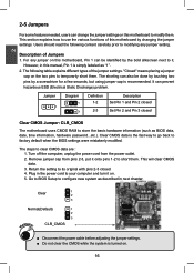
...Discharge) problem. Jumper 1 Diagram 1 1 Definition 1-2 2-3 Description Set Pin 1 and Pin 2 closed Set Pin 2 and Pin 3 closed Clear CMOS Jumper: CLR_CMOS The motherboard uses CMOS RAM to its original with pins 2-3 closed. 4. 2 2-5 Jumpers For some features needed, users can change the jumper settings on this... motherboard to clear CMOS data are : 1. The following content carefully prior to your computer and turn it . The steps to modify them . ...
...Discharge) problem. Jumper 1 Diagram 1 1 Definition 1-2 2-3 Description Set Pin 1 and Pin 2 closed Set Pin 2 and Pin 3 closed Clear CMOS Jumper: CLR_CMOS The motherboard uses CMOS RAM to its original with pins 2-3 closed. 4. 2 2-5 Jumpers For some features needed, users can change the jumper settings on this... motherboard to clear CMOS data are : 1. The following content carefully prior to your computer and turn it . The steps to modify them . ...

User manual
Page 24
... embed- CAUTION 17 Intel® Management Engine (ME) is closed, the system will send a message out. 1 INTRUDERJ GND C_INTRUSION1 Intel® ME Jumper: MFG This motherboard uses MFG jumper to a security switch on the chassis. TRUSION1 The connector can detect the chassis intrusion through the function of corporate assets. Set the...
... embed- CAUTION 17 Intel® Management Engine (ME) is closed, the system will send a message out. 1 INTRUDERJ GND C_INTRUSION1 Intel® ME Jumper: MFG This motherboard uses MFG jumper to a security switch on the chassis. TRUSION1 The connector can detect the chassis intrusion through the function of corporate assets. Set the...
User manual
Page 30
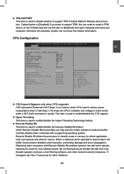
... halt worm attacks, reducing the need for other initiatives. 23 If you want to support TPM, first you need to install a TPM device on the motherboard and set this item to classify areas in halt state. Turbo Mode Enabled F 1: G e n e r a l Help CPU C6 Report [Enabled] F2: Previous Values Package C State limit [No...
... halt worm attacks, reducing the need for other initiatives. 23 If you want to support TPM, first you need to install a TPM device on the motherboard and set this item to classify areas in halt state. Turbo Mode Enabled F 1: G e n e r a l Help CPU C6 Report [Enabled] F2: Previous Values Package C State limit [No...

User manual
Page 31
.../disable the EIST (Processor Power Management, PPM) through this feature and the setting is supporting this item. ! This item will be met, including CPU, chipset, motherboard, BIOS and operation system. There are some system requirements must be displayed only when the CPU is used to dynamically adjust processor voltage and core...
.../disable the EIST (Processor Power Management, PPM) through this feature and the setting is supporting this item. ! This item will be met, including CPU, chipset, motherboard, BIOS and operation system. There are some system requirements must be displayed only when the CPU is used to dynamically adjust processor voltage and core...


