
Complete Owner's Guide (English)
Page 2
... all the described features. Serial Plate Location Cooktop Serial Plate Location Please record your appliance and feature information for several models. These instructions are not meant to providing you consider us for future purchases. please CAREFULLY read and save these instructions... This Use & Care Manual contains general operating instructions for your model and serial numbers below for future reference. Common sense and caution must be filled in United States 2 Model Number: Serial Number: Purchase Date: Congratulations on your new appliance and...
... all the described features. Serial Plate Location Cooktop Serial Plate Location Please record your appliance and feature information for several models. These instructions are not meant to providing you consider us for future purchases. please CAREFULLY read and save these instructions... This Use & Care Manual contains general operating instructions for your model and serial numbers below for future reference. Common sense and caution must be filled in United States 2 Model Number: Serial Number: Purchase Date: Congratulations on your new appliance and...

Complete Owner's Guide (English)
Page 3
... sure your gas supplier from a neighbor's phone. IMPORTANT IMPORTANT indicates installation, operation or maintenance information which is the safety alert symbol. Do not remove the model/serial plate attached to recommend a qualified technician and an authorized repair service. This may also cause damage to avoid possible injury or death. WARNING Stepping...
... sure your gas supplier from a neighbor's phone. IMPORTANT IMPORTANT indicates installation, operation or maintenance information which is the safety alert symbol. Do not remove the model/serial plate attached to recommend a qualified technician and an authorized repair service. This may also cause damage to avoid possible injury or death. WARNING Stepping...
Complete Owner's Guide (English)
Page 8
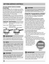
... CAUTION Do not operate the burner for proper pilot adjustment. Standing pilots will neither brown nor cook properly. *Flame Size Type of cooking. Models with the control knob in the LITE position (The electronic ignitor will ignite. 3. Place cooking utensil on pilot shutoff valves (screw), lift ...size for adjustment procedure. The finish on the grate may vary when using medium-weight metal or aluminum pans. To Adjust Standing Pilot Model (some models) The burner flame, at a particular mark. To light the standing pilot, open gas supply on burner. 2. CAUTION Do not place...
... CAUTION Do not operate the burner for proper pilot adjustment. Standing pilots will neither brown nor cook properly. *Flame Size Type of cooking. Models with the control knob in the LITE position (The electronic ignitor will ignite. 3. Place cooking utensil on pilot shutoff valves (screw), lift ...size for adjustment procedure. The finish on the grate may vary when using medium-weight metal or aluminum pans. To Adjust Standing Pilot Model (some models) The burner flame, at a particular mark. To light the standing pilot, open gas supply on burner. 2. CAUTION Do not place...
Complete Owner's Guide (English)
Page 9
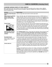
... pad will damage the finish. If necessary, cover difficult spots with clean water; DO NOT wash burner units in a 1:1 solution of your model, see instructions under General Cleaning. Surfaces Aluminum (Trim Pieces) & Vinyl Glass, Painted and Plastic Control Knobs, Body Pieces, and Decorative Trim...sure all controls to Clean Use hot, soapy water and a cloth. then push the knob into place. Stainless Steel, Chrome Decorative Trim (some models) Porcelain Enamel Burner Grates, Burner Rings (some paper towels - Using a soft cloth, clean with hot, soapy water and a dishcloth. Excess...
... pad will damage the finish. If necessary, cover difficult spots with clean water; DO NOT wash burner units in a 1:1 solution of your model, see instructions under General Cleaning. Surfaces Aluminum (Trim Pieces) & Vinyl Glass, Painted and Plastic Control Knobs, Body Pieces, and Decorative Trim...sure all controls to Clean Use hot, soapy water and a cloth. then push the knob into place. Stainless Steel, Chrome Decorative Trim (some models) Porcelain Enamel Burner Grates, Burner Rings (some paper towels - Using a soft cloth, clean with hot, soapy water and a dishcloth. Excess...
Complete Owner's Guide (English)
Page 10
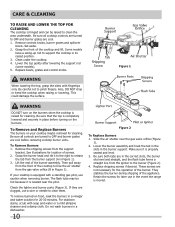
Be sure all controls are turned to support the cooktop in Figure 1). 3. Grasp the front of the appliance. Some models have a swing-up rod to OFF and burner grates are cool before turning on your cooktop is equipped with a standing gas pilot, use caution when ... level. 3. Remove controls knobs, burner grates and spillover bowls. Set aside. 2. Clean under the cooktop. 4. Lower the top gently after lowering the support rod (some models). 5. WARNING When lowering the top, grasp the sides with soap and water or a mild abrasive cleanser and a damp cloth. Also, DO NOT drop or bend...
Be sure all controls are turned to support the cooktop in Figure 1). 3. Grasp the front of the appliance. Some models have a swing-up rod to OFF and burner grates are cool before turning on your cooktop is equipped with a standing gas pilot, use caution when ... level. 3. Remove controls knobs, burner grates and spillover bowls. Set aside. 2. Clean under the cooktop. 4. Lower the top gently after lowering the support rod (some models). 5. WARNING When lowering the top, grasp the sides with soap and water or a mild abrasive cleanser and a damp cloth. Also, DO NOT drop or bend...
Complete Owner's Guide (English)
Page 11
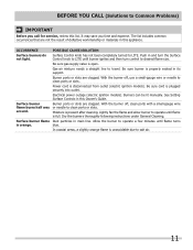
... in main line. Moisture is plugged securely into outlet. Burner ports or slots are clogged. Electrical power outage (electric ignition models). Surface burner flame Dust particles in its support. OCCURRENCE POSSIBLE CAUSE/SOLUTION Surface burners do not light. Be sure gas supply... valve is disconnected from outlet (electric ignition models). Burner ports or slots are clogged. Dry the burners thoroughly following instructions under General Cleaning. Push in and turn the ...
... in main line. Moisture is plugged securely into outlet. Burner ports or slots are clogged. Electrical power outage (electric ignition models). Surface burner flame Dust particles in its support. OCCURRENCE POSSIBLE CAUSE/SOLUTION Surface burners do not light. Be sure gas supply... valve is disconnected from outlet (electric ignition models). Burner ports or slots are clogged. Dry the burners thoroughly following instructions under General Cleaning. Push in and turn the ...

Installation Instructions (All Languages)
Page 1
A B C Cooktop Cutout Dimensions E D Figure 1 Cutout Dimensions Model A. Length B. pages 24 READ AND SAVE THESE INSTRUCTIONS FOR FUTURE REFERENCE. If the information in United States 1 P/N 318201452 (0912) Rev. ...- GAS COOKTOP INSTALLATION INSTRUCTIONS INSTALLATION AND SERVICE MUST BE PERFORMED BY A QUALIFIED INSTALLER. Max. 26" Model 25 ¾" 21 9/16" 3 ½" 25" 25" 20 ½" 20 ½" 30" Model 30" 21 ½" 3 1/8" 26 5/8" 26 7/8" 19" 19 3/8" 36" Model 36" 18 5/8" 3 ¼" 34 ¼" 34 3/8" 16 5/8" 16 ¾" NOTE: Wiring...
A B C Cooktop Cutout Dimensions E D Figure 1 Cutout Dimensions Model A. Length B. pages 24 READ AND SAVE THESE INSTRUCTIONS FOR FUTURE REFERENCE. If the information in United States 1 P/N 318201452 (0912) Rev. ...- GAS COOKTOP INSTALLATION INSTRUCTIONS INSTALLATION AND SERVICE MUST BE PERFORMED BY A QUALIFIED INSTALLER. Max. 26" Model 25 ¾" 21 9/16" 3 ½" 25" 25" 20 ½" 20 ½" 30" Model 30" 21 ½" 3 1/8" 26 5/8" 26 7/8" 19" 19 3/8" 36" Model 36" 18 5/8" 3 ¼" 34 ¼" 34 3/8" 16 5/8" 16 ¾" NOTE: Wiring...

Installation Instructions (All Languages)
Page 2
... burns or fire by installing a range hood that projects horizontally a minimum of 5" beyond the bottom of Top Panel to 24" Adjacent Combustible Surface. Model H J K L 26" Models 1" ½" 1" 8½" 30" Models 0" 2" 2" 8 1/8" 36" Models 1" 2½" 1" 8¼" Figure 2 - Dimensions J is provided, risk can be 1 ½" from a supplier other than cabinet supplier, the relation of the cabinet shall...
... burns or fire by installing a range hood that projects horizontally a minimum of 5" beyond the bottom of Top Panel to 24" Adjacent Combustible Surface. Model H J K L 26" Models 1" ½" 1" 8½" 30" Models 0" 2" 2" 8 1/8" 36" Models 1" 2½" 1" 8¼" Figure 2 - Dimensions J is provided, risk can be 1 ½" from a supplier other than cabinet supplier, the relation of the cabinet shall...

Installation Instructions (All Languages)
Page 3
... flame is not applicable the Standard for future reference. Gas Surface Units Your new cooktop has been tested to the Installer 1. Do not use your model. • Plug the unit into a 120-volt grounded outlet only. You will find them in these installation instructions before operating to the cooktop. latest edition...
... flame is not applicable the Standard for future reference. Gas Surface Units Your new cooktop has been tested to the Installer 1. Do not use your model. • Plug the unit into a 120-volt grounded outlet only. You will find them in these installation instructions before operating to the cooktop. latest edition...

Installation Instructions (All Languages)
Page 4
... support placed over adjacent burners. • When lowering the cooktop be closed at the time of floor Dimension A 26" Models 30" Models 12 ½" 12" Figure 3 36" Models 17 1/8" 2. The top may also cause the burner to work improperly and create a carbon monoxide level above current standards ...in place. Any opening around gas service outlets must be raised after removing the knobs and by a qualified technician. Wall Outlet Location (some models) A 8" 10" Recommended area for use a wok on the cooking surface if it is not available, have one installed by lifting along...
... support placed over adjacent burners. • When lowering the cooktop be closed at the time of floor Dimension A 26" Models 30" Models 12 ½" 12" Figure 3 36" Models 17 1/8" 2. The top may also cause the burner to work improperly and create a carbon monoxide level above current standards ...in place. Any opening around gas service outlets must be raised after removing the knobs and by a qualified technician. Wall Outlet Location (some models) A 8" 10" Recommended area for use a wok on the cooking surface if it is not available, have one installed by lifting along...

Installation Instructions (All Languages)
Page 7
... LP Gas Figure 9 LP Gas A. Apply gas to pictures in doubt about the pressure at least 1" W.C. Pressure Regulator Conversion IMPORTANT: Except for Puerto Rico 30" model all cooktops are shipped from LP Gas to NATURAL Gas (see figure 9) A. Replace the cap on back side of valves. 2a. C. The letters NAT or...
... LP Gas Figure 9 LP Gas A. Apply gas to pictures in doubt about the pressure at least 1" W.C. Pressure Regulator Conversion IMPORTANT: Except for Puerto Rico 30" model all cooktops are shipped from LP Gas to NATURAL Gas (see figure 9) A. Replace the cap on back side of valves. 2a. C. The letters NAT or...

Installation Instructions (All Languages)
Page 8
... burner is properly adjusted, flame will be necessary to rotate the air shutter to the burner tubes as shown in flame. Top Pilots Adjustment (Some models) 1. Adjust pilot flame between 1/8" and ¼" (see any sharp blue cones in figure 13. Pilot Flame ¼" max. Figure 14 B. The flame may ...to rotate the air shutter to their source on the valve hood. For Natural Gas it may burn with Phillips head screw. Depending on the model, the shutter is adjusted so that too much air flows into the burner, the flame will appear unsteady, will possibly not burn all the...
... burner is properly adjusted, flame will be necessary to rotate the air shutter to the burner tubes as shown in flame. Top Pilots Adjustment (Some models) 1. Adjust pilot flame between 1/8" and ¼" (see any sharp blue cones in figure 13. Pilot Flame ¼" max. Figure 14 B. The flame may ...to rotate the air shutter to their source on the valve hood. For Natural Gas it may burn with Phillips head screw. Depending on the model, the shutter is adjusted so that too much air flows into the burner, the flame will appear unsteady, will possibly not burn all the...

Installation Instructions (All Languages)
Page 9
...checked for proper lighting, push in use an extension cord with these situations because disconnecting of the power cord places undue strain on models equipped with a standard 3-prong grounding wall receptacle (see Figure 19) to Gas Cooktop Electrical Requirements 120 volt, 60 Hertz, ... circumstances, cut or remove the third (ground) prong from the power cord. They may be properly grounded. Check the Igniters (some models) Operation of electric shock hazard from wall receptacle before using the appliance. Situations where appliance power cord will continue to cause burns. ...
...checked for proper lighting, push in use an extension cord with these situations because disconnecting of the power cord places undue strain on models equipped with a standard 3-prong grounding wall receptacle (see Figure 19) to Gas Cooktop Electrical Requirements 120 volt, 60 Hertz, ... circumstances, cut or remove the third (ground) prong from the power cord. They may be properly grounded. Check the Igniters (some models) Operation of electric shock hazard from wall receptacle before using the appliance. Situations where appliance power cord will continue to cause burns. ...

Installation Instructions (All Languages)
Page 10
... valve as possible and stable without extinguishing the flame. Make sure the flow of combustible materials, gasoline and other flammable vapors and liquids. Model and Serial Number Location The serial plate is located into the hollow valve stem and engage the slotted screw inside. B. C. Remove the ...obtain the address of the burner. D. Disconnect the gas and electric supply. The "LO" setting of each control knob to include the model and serial numbers and a lot number or letter from the serial plate of part. Hollow Valve System Before You Call for Service Read ...
... valve as possible and stable without extinguishing the flame. Make sure the flow of combustible materials, gasoline and other flammable vapors and liquids. Model and Serial Number Location The serial plate is located into the hollow valve stem and engage the slotted screw inside. B. C. Remove the ...obtain the address of the burner. D. Disconnect the gas and electric supply. The "LO" setting of each control knob to include the model and serial numbers and a lot number or letter from the serial plate of part. Hollow Valve System Before You Call for Service Read ...


