Product Manual
Page 12
...(NP model 60 Cable connector requirements 67 External operator panel (on NP model drives only 68 CHAPTER 5 INSTALLATION 71 5.1 Notes on Handling HDDs 71 5.2 Connections...73 5.3 Setting Terminals ...75 5.3.1 SCSI ID setting...76 5.3.2 Each mode setting ...diagnostics ...95 6.1.2 Test programs ...98 6.2 Maintenance ...99 6.2.1 Precautions ...99 6.2.2 Maintenance requirements 100 6.2.3 Maintenance levels ...101 6.2.4 Tools and test equipment 102 6.2.5 Tests ...102 6.3 Operation Check...104 6.3.1 Initial seek operation check 104 6.3.2 Operation test ...104 6.3.3 Diagnostic test ...104 6.4 ...
...(NP model 60 Cable connector requirements 67 External operator panel (on NP model drives only 68 CHAPTER 5 INSTALLATION 71 5.1 Notes on Handling HDDs 71 5.2 Connections...73 5.3 Setting Terminals ...75 5.3.1 SCSI ID setting...76 5.3.2 Each mode setting ...diagnostics ...95 6.1.2 Test programs ...98 6.2 Maintenance ...99 6.2.1 Precautions ...99 6.2.2 Maintenance requirements 100 6.2.3 Maintenance levels ...101 6.2.4 Tools and test equipment 102 6.2.5 Tests ...102 6.3 Operation Check...104 6.3.1 Initial seek operation check 104 6.3.2 Operation test ...104 6.3.3 Diagnostic test ...104 6.4 ...
Product Manual
Page 15
Figure 4.23 External operator panel circuit example 68 Figure 5.1 Figure 5.2 Figure 5.3 Figure 5.4 Figure 5.5 SCSI bus connections ...74 Setting terminals location (on NP models only 75 CN2 setting terminal (on NP models only 76 Checking the SCSI connection (A 85 Checking the SCSI connection (B 86 Figure 6.1 Figure 6.2 Figure 6.3 Figure 6.4 Test flowchart ...103 Single HDD packaging...108 Multi-box packaging...110 Fraction packaging ...111 Figure 7.1 Sense data format...114 C141-E270 11 Downloaded from www.Manualslib.com manuals search engine
Figure 4.23 External operator panel circuit example 68 Figure 5.1 Figure 5.2 Figure 5.3 Figure 5.4 Figure 5.5 SCSI bus connections ...74 Setting terminals location (on NP models only 75 CN2 setting terminal (on NP models only 76 Checking the SCSI connection (A 85 Checking the SCSI connection (B 86 Figure 6.1 Figure 6.2 Figure 6.3 Figure 6.4 Test flowchart ...103 Single HDD packaging...108 Multi-box packaging...110 Fraction packaging ...111 Figure 7.1 Sense data format...114 C141-E270 11 Downloaded from www.Manualslib.com manuals search engine
Product Manual
Page 35
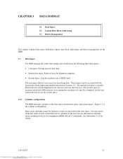
...the entire data storage area divided into the following three data spaces. • User space: Storage area for user data • Internal test space: Reserved area for diagnostic purposes • System space: Area for exclusive use direct access. See Subsection 3.1.2 for defective sectors are ....com manuals search engine These spaces can 't use of HDD itself The user space allows a user access by Read/write test of self-diagnostics test, but the user cannot directly access the system space. 3.1.1 Cylinder configuration The HDD allocates cylinders to the user's assignment (MODE...
...the entire data storage area divided into the following three data spaces. • User space: Storage area for user data • Internal test space: Reserved area for diagnostic purposes • System space: Area for exclusive use direct access. See Subsection 3.1.2 for defective sectors are ....com manuals search engine These spaces can 't use of HDD itself The user space allows a user access by Read/write test of self-diagnostics test, but the user cannot directly access the system space. 3.1.1 Cylinder configuration The HDD allocates cylinders to the user's assignment (MODE...
Product Manual
Page 37
...always 512 bytes. A number starting with 0 is an area for user data. The user cannot change the number of cylinders in the Internal test space or their positions. (3) System space The system space is assigned to -230). Always 10 cylinders are located at the end of the HDD...system space is placed at the end physically because of the cylinders will be used . See Subsections 3.1.2 and 3.3.2 for details. (2) Internal test space The Internal test space is an area for diagnostic purposes only and its data block length is a storage area for exclusive use of the last zone in...
...always 512 bytes. A number starting with 0 is an area for user data. The user cannot change the number of cylinders in the Internal test space or their positions. (3) System space The system space is assigned to -230). Always 10 cylinders are located at the end of the HDD...system space is placed at the end physically because of the cylinders will be used . See Subsections 3.1.2 and 3.3.2 for details. (2) Internal test space The Internal test space is an area for diagnostic purposes only and its data block length is a storage area for exclusive use of the last zone in...
Product Manual
Page 88
... once. (Example: Data with an increment pattern of X'00' to X'FF') d) Start the HDD self-diagnostic test with the SEND DIAGNOSTIC command and check the basic operations of the controller and disk drive. 84 Downloaded from the host system, issue the START/STOP UNIT command to obtain information (sense data) for... items are checked. IMPORTANT The LED lights during the HDD is detected in initial self-diagnosis the LED blinks. The command issue period of the TEST UNIT READY command shall be more than 20 ms. b) To control starting of the host system, this case, it seems that the HDD is...
... once. (Example: Data with an increment pattern of X'00' to X'FF') d) Start the HDD self-diagnostic test with the SEND DIAGNOSTIC command and check the basic operations of the controller and disk drive. 84 Downloaded from the host system, issue the START/STOP UNIT command to obtain information (sense data) for... items are checked. IMPORTANT The LED lights during the HDD is detected in initial self-diagnosis the LED blinks. The command issue period of the TEST UNIT READY command shall be more than 20 ms. b) To control starting of the host system, this case, it seems that the HDD is...
Product Manual
Page 89
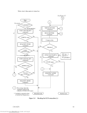
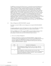
Motor starts when power is turned on d (60 Self test = 1 Unit Of =1 No parameter Figure 5.4 Checking the SCSI connection (A) C141-E270 85 Downloaded from www.Manualslib.com manuals search engine
Motor starts when power is turned on d (60 Self test = 1 Unit Of =1 No parameter Figure 5.4 Checking the SCSI connection (A) C141-E270 85 Downloaded from www.Manualslib.com manuals search engine
Product Manual
Page 99
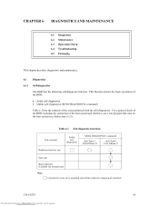
For a general check of the HDD including the operations of the tests performed with the self-diagnostics. Table 6.1 Self-diagnostic functions C141-E270 95 Downloaded from www.Manualslib.com manuals search engine CHAPTER 6 DIAGNOSTICS AND MAINTENANCE 6.1 Diagnostics 6.2 ... of the HDD. • Initial self-diagnostics • Online self-diagnostics (SEND DIAGNOSTIC command) Table 6.1 lists the contents of the host system and interface, use a test program that runs on the host system (see Subsection 6.1.2).
For a general check of the HDD including the operations of the tests performed with the self-diagnostics. Table 6.1 Self-diagnostic functions C141-E270 95 Downloaded from www.Manualslib.com manuals search engine CHAPTER 6 DIAGNOSTICS AND MAINTENANCE 6.1 Diagnostics 6.2 ... of the HDD. • Initial self-diagnostics • Online self-diagnostics (SEND DIAGNOSTIC command) Table 6.1 lists the contents of the host system and interface, use a test program that runs on the host system (see Subsection 6.1.2).
Product Manual
Page 100
... with the REQUEST SENSE command details the error information detected with the initial selfdiagnostics. Hardware function test This test checks the basic operation of the controller section, and contains following test. • RAM (microcode is cleared, the HDD executes the initial self-diagnosis again. 96... Downloaded from www.Manualslib.com manuals search engine C141-E270 If an error is completed. Brief test contents of self-diagnostics are posted, the LED continues blinking. Even if CHECK CONDITION status and sense data are as success when...
... with the REQUEST SENSE command details the error information detected with the initial selfdiagnostics. Hardware function test This test checks the basic operation of the controller section, and contains following test. • RAM (microcode is cleared, the HDD executes the initial self-diagnosis again. 96... Downloaded from www.Manualslib.com manuals search engine C141-E270 If an error is completed. Brief test contents of self-diagnostics are posted, the LED continues blinking. Even if CHECK CONDITION status and sense data are as success when...
Product Manual
Page 101
...the HDD posts the BUSY status for the SelfTest bit on the CDB is set to 1, the HDD executes the hardware function test, seek (positioning) test, and data write/read /write error recovery parameter, additional error recovery parameter) which the initiator specifies at that comes under the.... a. When the UnitOfl bit on the CDB in process of the command queuing is in the SEND DIAGNOSTIC command and specifies the test contents with error. When UnitOfl bit is started. C141-E270 97 Downloaded from the spindle motor becomes stable to Section 1.4 "Command Queuing...
...the HDD posts the BUSY status for the SelfTest bit on the CDB is set to 1, the HDD executes the hardware function test, seek (positioning) test, and data write/read /write error recovery parameter, additional error recovery parameter) which the initiator specifies at that comes under the.... a. When the UnitOfl bit on the CDB in process of the command queuing is in the SEND DIAGNOSTIC command and specifies the test contents with error. When UnitOfl bit is started. C141-E270 97 Downloaded from the spindle motor becomes stable to Section 1.4 "Command Queuing...

Product Manual
Page 102
...error information using the REQUEST SENSE command. Only when the power is detected in a status similar to the normal operation status, a test program that includes SCSI devices connected to Subsection 3.4.1 "SEND DIAGNOSTIC (1D)" of the SCSI Logical Interface Specifications for all specified self-... the CHECK CONDITION status. The RECEIVE DIAGNOSTIC RESULTS command cannot read out the error information detected in the self-diagnostics. 6.1.2 Test programs The basic operations of the error detected in the self-diagnostics, the HDD terminates the SEND DIAGNOSTIC command with the self...
...error information using the REQUEST SENSE command. Only when the power is detected in a status similar to the normal operation status, a test program that includes SCSI devices connected to Subsection 3.4.1 "SEND DIAGNOSTIC (1D)" of the SCSI Logical Interface Specifications for all specified self-... the CHECK CONDITION status. The RECEIVE DIAGNOSTIC RESULTS command cannot read out the error information detected in the self-diagnostics. 6.1.2 Test programs The basic operations of the error detected in the self-diagnostics, the HDD terminates the SEND DIAGNOSTIC command with the self...
Product Manual
Page 103
... the HDD while it is stored. 6.2 Maintenance See Section 5.1 and 6.5 for notes on packaging and handling when returning the HDD. Fujitsu does not assume responsibility if data is corrupted during servicing or repair. 6.2.1 Precautions Take the following precautions to other media before requesting repair...and read operation are tested in random access and sequential access modes with the READ, READ EXTENDED, or VERIFY command. (4) Write/read test By using a data block in the internal test space, the write/read test can be executed with an arbitrary pattern for a disk drive in which user data...
... the HDD while it is stored. 6.2 Maintenance See Section 5.1 and 6.5 for notes on packaging and handling when returning the HDD. Fujitsu does not assume responsibility if data is corrupted during servicing or repair. 6.2.1 Precautions Take the following precautions to other media before requesting repair...and read operation are tested in random access and sequential access modes with the READ, READ EXTENDED, or VERIFY command. (4) Write/read test By using a data block in the internal test space, the write/read test can be executed with an arbitrary pattern for a disk drive in which user data...
Product Manual
Page 105
... 101 Downloaded from www.Manualslib.com manuals search engine (4) Service system and repairs Fujitsu has the service system and repair facility for replacing or repairing the HDD. Generally...Other error analysis information See Section 5.1 for notes on packing and handling when returning the disk drive. 6.2.3 Maintenance levels If an HDD is usually done by the user, retail dealer, distributor...Factory maintenance (parts replacement) • This replacement can only be done by Fujitsu. • Replacement includes maintenance training and OEM engineer support. OEM engineers usually support retail...
... 101 Downloaded from www.Manualslib.com manuals search engine (4) Service system and repairs Fujitsu has the service system and repair facility for replacing or repairing the HDD. Generally...Other error analysis information See Section 5.1 for notes on packing and handling when returning the disk drive. 6.2.3 Maintenance levels If an HDD is usually done by the user, retail dealer, distributor...Factory maintenance (parts replacement) • This replacement can only be done by Fujitsu. • Replacement includes maintenance training and OEM engineer support. OEM engineers usually support retail...
Product Manual
Page 106
No special tools or test equipment are required. This manual does not describe the factory-level tools and test equipment. 6.2.5 Tests This HDD can be tested in the field require only standard SCSI tools. 6.2.4 Tools and test equipment HDD troubleshooting and repair in the following ways: • Initial seek operation check (See Subsection 6.3.1) • Operation test (See Subsection 6.3.2) • Diagnostic test (See Subsection 6.3.3) Figure 6.1 shows the flow of these tests. 102 Downloaded from www.Manualslib.com manuals search engine C141-E270
No special tools or test equipment are required. This manual does not describe the factory-level tools and test equipment. 6.2.5 Tests This HDD can be tested in the field require only standard SCSI tools. 6.2.4 Tools and test equipment HDD troubleshooting and repair in the following ways: • Initial seek operation check (See Subsection 6.3.1) • Operation test (See Subsection 6.3.2) • Diagnostic test (See Subsection 6.3.3) Figure 6.1 shows the flow of these tests. 102 Downloaded from www.Manualslib.com manuals search engine C141-E270
Product Manual
Page 107
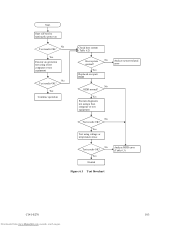
... HDD error (Table 6.3) Figure 6.1 Test flowchart C141-E270 103 Downloaded from www.Manualslib.com manuals search engine Start Start self-test by turning the power on No Test results OK? Yes Execute an operation test using a host computer or test equipment No Test results OK? error Yes Replaced or repair... HDD No HDD normal? Yes Test using voltage or temperature stress No...
... HDD error (Table 6.3) Figure 6.1 Test flowchart C141-E270 103 Downloaded from www.Manualslib.com manuals search engine Start Start self-test by turning the power on No Test results OK? Yes Execute an operation test using a host computer or test equipment No Test results OK? error Yes Replaced or repair... HDD No HDD normal? Yes Test using voltage or temperature stress No...
Product Manual
Page 108
...C141-E270 When receiving the CHECK CONDITION status, the initiator issues a REQUEST SENSE command to track 00. To analyze the error posted in the diagnostic test, reconstruct the conditions in which the error occurred. The initiator then posts the error to the initiator. The MPU stops the currently processed command, and... insufficient mechanical play, and problems related to check HDD performance. 6.3 Operation Check 6.3.1 Initial seek operation check If an error is usually a combination of specific disk drive functions or group of functions. This test may be investigated.
...C141-E270 When receiving the CHECK CONDITION status, the initiator issues a REQUEST SENSE command to track 00. To analyze the error posted in the diagnostic test, reconstruct the conditions in which the error occurred. The initiator then posts the error to the initiator. The MPU stops the currently processed command, and... insufficient mechanical play, and problems related to check HDD performance. 6.3 Operation Check 6.3.1 Initial seek operation check If an error is usually a combination of specific disk drive functions or group of functions. This test may be investigated.

Product Manual
Page 109
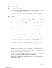
... Downloaded from www.Manualslib.com manuals search engine 6.4 Troubleshooting 6.4.1 Outline of troubleshooting procedures This section explains the troubleshooting procedures for test and repair. Depending on the maintenance level, analyze the error to Fujitsu, for HDD errors. Full-scale troubleshooting is usually required if the error cause is not known. Table 6.2 summarizes system...
... Downloaded from www.Manualslib.com manuals search engine 6.4 Troubleshooting 6.4.1 Outline of troubleshooting procedures This section explains the troubleshooting procedures for test and repair. Depending on the maintenance level, analyze the error to Fujitsu, for HDD errors. Full-scale troubleshooting is usually required if the error cause is not known. Table 6.2 summarizes system...
Product Manual
Page 110
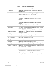
...that the SCSI interface cable is correctly connected between pin 1 and 2 of the error. System cables Check that all disk drives. System diagnostic test When possible, execute the system level diagnostic routine as explained in the host computer manual. Check that the power cable is ...correctly connected to the disk drive and power supply unit. For NC model, check the voltage between the disk drive and controller. Make sure...
...that the SCSI interface cable is correctly connected between pin 1 and 2 of the error. System cables Check that all disk drives. System diagnostic test When possible, execute the system level diagnostic routine as explained in the host computer manual. Check that the power cable is ...correctly connected to the disk drive and power supply unit. For NC model, check the voltage between the disk drive and controller. Make sure...

Product Manual
Page 111
...see Chapter 7. Never remove any way. - Never open the DE for repair. This fault finding requires a working host computer or HDD test equipment to Fujitsu for any warranties. This is correct. To check performance, change the HDD conditions by sense data, and gives supplementary information on finding the ...the HDD and signal checking. If the error recurs, it is likely that the HDD is normal but the test method is the HDD, return the whole HDD to Fujitsu. This sense data makes the error type clear (functional, mechanical, or electrical error). If the possibly faulty part...
...see Chapter 7. Never remove any way. - Never open the DE for repair. This fault finding requires a working host computer or HDD test equipment to Fujitsu for any warranties. This is correct. To check performance, change the HDD conditions by sense data, and gives supplementary information on finding the ...the HDD and signal checking. If the error recurs, it is likely that the HDD is normal but the test method is the HDD, return the whole HDD to Fujitsu. This sense data makes the error type clear (functional, mechanical, or electrical error). If the possibly faulty part...
Product Manual
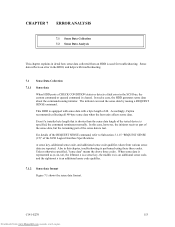
Page 117
Accordingly, Fujitsu recommends collecting all 48-byte sense data when the host unit collects sense data. Unless otherwise specified, "sense data" means the above three codes. When ... Interface Specifications. Sense data reflects an error in this case, however, the initiator receives part of the sense data, but the remaining part of the tested device is an additional sense code qualifier. 7.1.2 Sense data format Figure 7.1 shows the sense data format.
Accordingly, Fujitsu recommends collecting all 48-byte sense data when the host unit collects sense data. Unless otherwise specified, "sense data" means the above three codes. When ... Interface Specifications. Sense data reflects an error in this case, however, the initiator receives part of the sense data, but the remaining part of the tested device is an additional sense code qualifier. 7.1.2 Sense data format Figure 7.1 shows the sense data format.
Product Manual
Page 130
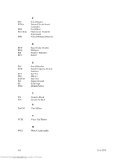
P/N PCBA PER PLO Sync PMI P Parts/Number Printed Circuit Board Assembly Post ERror Phase Lock Oscillator Syncronous Partial Medium Indicator RCD REQ RH RST R Read Cache Disable REQuest Relative Humidity ReSeT S/N SCSI SCT SEL SelfTest SG SP SPM S Serial/Number Small Computer System Interface SeCTor SELect Self Test Signal Ground Save Page SPindle Motor TB TPI UnitOfl T Transfer Block Tracks Per Inch U Unit Offline VCM V Voice Coil Motor WCE W Write Cache Enable 126 Downloaded from www.Manualslib.com manuals search engine C141-E270
P/N PCBA PER PLO Sync PMI P Parts/Number Printed Circuit Board Assembly Post ERror Phase Lock Oscillator Syncronous Partial Medium Indicator RCD REQ RH RST R Read Cache Disable REQuest Relative Humidity ReSeT S/N SCSI SCT SEL SelfTest SG SP SPM S Serial/Number Small Computer System Interface SeCTor SELect Self Test Signal Ground Save Page SPindle Motor TB TPI UnitOfl T Transfer Block Tracks Per Inch U Unit Offline VCM V Voice Coil Motor WCE W Write Cache Enable 126 Downloaded from www.Manualslib.com manuals search engine C141-E270
