
Product Manual
Page 9
Command Processing 3. MANUAL ORGANIZATION PRODUCT MANUAL (This manual) SAS INTERFACE MANUAL 1. Specifications 3. Diagnostics and Maintenance 7. Command Specifications 5. General Description 2. Error Analysis 1. Disk Media Management C141-E252 5 SAS Interface 2. Parameter Data Format 6. Installation Requirements 5. Sense Data and Error Recovery Methods 7. Data Buffer Management 4. Data Format 4. Installation 6.
Command Processing 3. MANUAL ORGANIZATION PRODUCT MANUAL (This manual) SAS INTERFACE MANUAL 1. Specifications 3. Diagnostics and Maintenance 7. Command Specifications 5. General Description 2. Error Analysis 1. Disk Media Management C141-E252 5 SAS Interface 2. Parameter Data Format 6. Installation Requirements 5. Sense Data and Error Recovery Methods 7. Data Buffer Management 4. Data Format 4. Installation 6.
Product Manual
Page 16
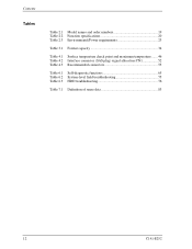
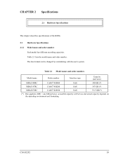
Contents Tables Table 2.1 Model names and order numbers 19 Table 2.2 Function specifications 20 Table 2.3 Environmental/Power requirements 23 Table 3.1 Format capacity 34 Table 4.1 Surface temperature check point and maximum temperature ....... 46 Table 4.2 Interface connector (SAS plug) signal allocation:CN1 52 Table 4.3 Recommended connectors 53 Table 6.1 Self-diagnostic functions 65 Table 6.2 System-level field troubleshooting 75 Table 6.3 HDD troubleshooting 76 Table 7.1 Definition of sense data 83 12 C141-E252
Contents Tables Table 2.1 Model names and order numbers 19 Table 2.2 Function specifications 20 Table 2.3 Environmental/Power requirements 23 Table 3.1 Format capacity 34 Table 4.1 Surface temperature check point and maximum temperature ....... 46 Table 4.2 Interface connector (SAS plug) signal allocation:CN1 52 Table 4.3 Recommended connectors 53 Table 6.1 Self-diagnostic functions 65 Table 6.2 System-level field troubleshooting 75 Table 6.3 HDD troubleshooting 76 Table 7.1 Definition of sense data 83 12 C141-E252

Product Manual
Page 17
...8226; Full-duplex (simultaneous bidirectional data transfer) is supported. C141-E252 13 The interface used to connect the HDDs to the host system complies with a serial attached SCSI (SAS) as a host interface. • Transfer rate: 1.5Gbps, 3.0Gbps • Number of high-performance ...Union (EU). (3) SAS Standard The HDDs are high performance large capacity 3.5-inch hard disk drives with an embedded Serial Attached SCSI (SAS) controller. The HDDs are equipped with ANSI T10/1601-D Serial Attached SCSI-1.1 (SAS-1.1), which complies with the 3.5-inch hard disk drive form factor. (2) ...
...8226; Full-duplex (simultaneous bidirectional data transfer) is supported. C141-E252 13 The interface used to connect the HDDs to the host system complies with a serial attached SCSI (SAS) as a host interface. • Transfer rate: 1.5Gbps, 3.0Gbps • Number of high-performance ...Union (EU). (3) SAS Standard The HDDs are high performance large capacity 3.5-inch hard disk drives with an embedded Serial Attached SCSI (SAS) controller. The HDDs are equipped with ANSI T10/1601-D Serial Attached SCSI-1.1 (SAS-1.1), which complies with the 3.5-inch hard disk drive form factor. (2) ...
Product Manual
Page 23
... changed by reinitializing with the user's system. Table 2.1 Model names and order numbers Model name Order number Interface type Capacity (user area) MBA3300RC CA06778-B400 SAS 300 GB (*) MBA3147RC CA06778-B200 SAS 147 GB (*) MBA3073RC CA06778-B100 SAS 73.5 GB (*) (*) One gigabyte (GB) = one billion bytes; The data format can be less and actual capacity depends on the operating environment...
... changed by reinitializing with the user's system. Table 2.1 Model names and order numbers Model name Order number Interface type Capacity (user area) MBA3300RC CA06778-B400 SAS 300 GB (*) MBA3147RC CA06778-B200 SAS 147 GB (*) MBA3073RC CA06778-B100 SAS 73.5 GB (*) (*) One gigabyte (GB) = one billion bytes; The data format can be less and actual capacity depends on the operating environment...

Product Manual
Page 40
... G lists by the READ DEFECT DATA command. 3.3.2 Alternate block allocation The alternate data block is allocated to Subsection 6.3.2 "Auto alternate block allocation processing" of the SAS INTERFACE MANUAL for details. On the other hand, the logical data block is allocated to spare sectors which alternate blocks are not physically consecutive to which...
... G lists by the READ DEFECT DATA command. 3.3.2 Alternate block allocation The alternate data block is allocated to Subsection 6.3.2 "Auto alternate block allocation processing" of the SAS INTERFACE MANUAL for details. On the other hand, the logical data block is allocated to spare sectors which alternate blocks are not physically consecutive to which...
Product Manual
Page 55
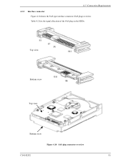
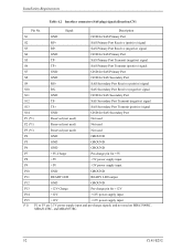
Top view Bottom view Top view Bottom view Figure 4.10 SAS plug connector overview C141-E252 51 4.3 Connection Requirements 4.3.2 Interface connector Figure 4.10 shows the SAS type interface connector (SAS plug) overview. Table 4.2 lists the signal allocation of the SAS plug on the HDDs.
Top view Bottom view Top view Bottom view Figure 4.10 SAS plug connector overview C141-E252 51 4.3 Connection Requirements 4.3.2 Interface connector Figure 4.10 shows the SAS type interface connector (SAS plug) overview. Table 4.2 lists the signal allocation of the SAS plug on the HDDs.
Product Manual
Page 56
... P3 (*1) Reserved (not used) Not used on MBA3300RC, MBA3147RC, and MBA3073RC. 52 C141-E252 SAS Secondary Port Receive (negative) signal S11 GND GND for SAS Secondary Port S9 RS+ SAS Secondary Port Receive (positive) signal S10 RS- Installation Requirements Table 4.2 Interface connector (SAS plug) signal allocation:CN1 Pin No. SAS Primary Port Transmit (negative) signal S6 TP...
... P3 (*1) Reserved (not used) Not used on MBA3300RC, MBA3147RC, and MBA3073RC. 52 C141-E252 SAS Secondary Port Receive (negative) signal S11 GND GND for SAS Secondary Port S9 RS+ SAS Secondary Port Receive (positive) signal S10 RS- Installation Requirements Table 4.2 Interface connector (SAS plug) signal allocation:CN1 Pin No. SAS Primary Port Transmit (negative) signal S6 TP...
Product Manual
Page 61
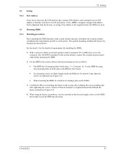
...the HDDs are used. 5.3 Mounting HDDs 5.3.1 Mounting procedures Since mounting the HDD depends on the HDD that uses the SAS interface has a unique SAS address, and commands use an SAS address to access the connector after tightening the screws. Fix the HDD by using an electric screwdriver, use the screwdriver ...mounting screws of requirements for I/O operations. 5.2 Setting 5.2 Setting 5.2.1 Port Address Every device that would exceed the HDD specifications. Every HDD is assigned a unique SAS address before shipment from the factory, so setting of both sides: 3 × 2, bottom: 4).
...the HDDs are used. 5.3 Mounting HDDs 5.3.1 Mounting procedures Since mounting the HDD depends on the HDD that uses the SAS interface has a unique SAS address, and commands use an SAS address to access the connector after tightening the screws. Fix the HDD by using an electric screwdriver, use the screwdriver ...mounting screws of requirements for I/O operations. 5.2 Setting 5.2 Setting 5.2.1 Port Address Every device that would exceed the HDD specifications. Every HDD is assigned a unique SAS address before shipment from the factory, so setting of both sides: 3 × 2, bottom: 4).

Product Manual
Page 62
... on the host system configuration. b) When the SAS protocol controller diagnosis is issued. d) The LED blinks (flashes on is completed normally, the host system checks whether the HDD connection to commands from the host. (2) Verifying interface connection: When verification of initial operation after power...INQUIRY, WRITE BUFFER, and READ BUFFER commands to verify that the transfer rate and HDD SAS addresses can use the TEST UNIT READY command to confirm that the HDDs are in the interface. (3) Verifying HDD operation : When the LINK RESET sequence has completed, the host system...
... on the host system configuration. b) When the SAS protocol controller diagnosis is issued. d) The LED blinks (flashes on is completed normally, the host system checks whether the HDD connection to commands from the host. (2) Verifying interface connection: When verification of initial operation after power...INQUIRY, WRITE BUFFER, and READ BUFFER commands to verify that the transfer rate and HDD SAS addresses can use the TEST UNIT READY command to confirm that the HDDs are in the interface. (3) Verifying HDD operation : When the LINK RESET sequence has completed, the host system...

Product Manual
Page 63
...Preparing the HDDs for Use c) Issue the REQUEST SENSE command to Chapter 6 "Sense Data and Error Recovery Method" of the SAS INTERFACE MANUAL for further details. 5.4.2 Formatting Since the HDD is formatted with the MODE SELECT or MODE SELECT EXTENDED command. To explicitly... field (cannot be formatted (initialized) according to check for recoverable errors, and retry operations for recovery from the default format, all sides of the SAS INTERFACE MANUAL for a recoverable error. Refer to Subsection 4.1.4 "MODE SELECT (15)", 4.1.5 "MODE SELECT EXTENDED (55)", 4.3.1 "FORMAT UNIT (04)", and...
...Preparing the HDDs for Use c) Issue the REQUEST SENSE command to Chapter 6 "Sense Data and Error Recovery Method" of the SAS INTERFACE MANUAL for further details. 5.4.2 Formatting Since the HDD is formatted with the MODE SELECT or MODE SELECT EXTENDED command. To explicitly... field (cannot be formatted (initialized) according to check for recoverable errors, and retry operations for recovery from the default format, all sides of the SAS INTERFACE MANUAL for a recoverable error. Refer to Subsection 4.1.4 "MODE SELECT (15)", 4.1.5 "MODE SELECT EXTENDED (55)", 4.3.1 "FORMAT UNIT (04)", and...
Product Manual
Page 65
... the parameter value set the default values for the system. This enables the HDDs to Subsection 4.1.4 "MODE SELECT (15)", 4.1.5 "MODE SELECT EXTENDED (55)" of the SAS INTERFACE MANUAL for all initiator. To obtain the best performance, set parameters, the HDDs operates according to the default value of the system requirements specific to...
... the parameter value set the default values for the system. This enables the HDDs to Subsection 4.1.4 "MODE SELECT (15)", 4.1.5 "MODE SELECT EXTENDED (55)" of the SAS INTERFACE MANUAL for all initiator. To obtain the best performance, set parameters, the HDDs operates according to the default value of the system requirements specific to...

Product Manual
Page 67
... parameters can be re-set actively. 3. 5.4 Checking Operation after Installation and Preparing the HDDs for further details. a. Refer to Chapter 3 "Data Buffer Management" of the SAS INTERFACE MANUAL for Use (2) Caching parameters (page code = 8) The following parameters are disabled by enabling Read-Ahead caching operations and Write Cache feature. (3) Control mode parameters...
... parameters can be re-set actively. 3. 5.4 Checking Operation after Installation and Preparing the HDDs for further details. a. Refer to Chapter 3 "Data Buffer Management" of the SAS INTERFACE MANUAL for Use (2) Caching parameters (page code = 8) The following parameters are disabled by enabling Read-Ahead caching operations and Write Cache feature. (3) Control mode parameters...

Product Manual
Page 72
...-E252 When this status is turned off or re-turned on other I /O operation request except the REQUEST SENSE command. The structure and functions of the SAS INTERFACE MANUAL for all I /O ports. Only when the power is cleared, the HDDs execute the initial self-diagnostics again (see Subsection 6.1.1). (3) Random/sequential read test The... error is read operation are tested in random access and sequential access modes with the self-diagnostic function. Refer to test the HDD functions generally. (1) Interface test The operations of the data buffer on the user system requirements.
...-E252 When this status is turned off or re-turned on other I /O operation request except the REQUEST SENSE command. The structure and functions of the SAS INTERFACE MANUAL for all I /O ports. Only when the power is cleared, the HDDs execute the initial self-diagnostics again (see Subsection 6.1.1). (3) Random/sequential read test The... error is read operation are tested in random access and sequential access modes with the self-diagnostic function. Refer to test the HDD functions generally. (1) Interface test The operations of the data buffer on the user system requirements.

Product Manual
Page 87
... an invalid operation code, occurred. 44 xx A hardware error occurred inside HDDs. 47 xx An interface error occurred. 4B xx An interface error occurred. 4E 00 An overlap command was issued. Sense key 3 4 1 3 E 5 4 B Table 7.1 Definition of the SAS INTERFACE MANUAL. 7.2 Sense Data Analysis 7.2 Sense Data Analysis 7.2.1 Error information indicated with sense data Table 7.1 lists...
... an invalid operation code, occurred. 44 xx A hardware error occurred inside HDDs. 47 xx An interface error occurred. 4B xx An interface error occurred. 4E 00 An overlap command was issued. Sense key 3 4 1 3 E 5 4 B Table 7.1 Definition of the SAS INTERFACE MANUAL. 7.2 Sense Data Analysis 7.2 Sense Data Analysis 7.2.1 Error information indicated with sense data Table 7.1 lists...
Product Manual
Page 88
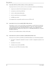
...and (B-4E-00) indicates one of a disk, there is disk damage that was issued, or invalid or unsupported parameters were specified. • An interface error occurred. • A hardware error occurred inside HDDs. In this error occurs in a specific block of the following symptoms: • An invalid ...1x-xx) or (E-1D-00) occurs frequently in different blocks, a PCBA or DE is faulty. 84 C141-E252 For an explanation of the SAS INTERFACE MANUAL. If this case, assign an alternate block to Subsection 4.3.2 "REASSIGN BLOCKS (07)" of the REASSIGN BLOCKS command, refer to the error-...
...and (B-4E-00) indicates one of a disk, there is disk damage that was issued, or invalid or unsupported parameters were specified. • An interface error occurred. • A hardware error occurred inside HDDs. In this error occurs in a specific block of the following symptoms: • An invalid ...1x-xx) or (E-1D-00) occurs frequently in different blocks, a PCBA or DE is faulty. 84 C141-E252 For an explanation of the SAS INTERFACE MANUAL. If this case, assign an alternate block to Subsection 4.3.2 "REASSIGN BLOCKS (07)" of the REASSIGN BLOCKS command, refer to the error-...
Product Manual
Page 89
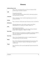
...is a command to a target to the target. It contains information for reporting detailed information on the SAS bus. SCSI Small Computer System Interface The standardized input/output interface of the American National Standards Institute (ANSI). [Standard No.: ANSI X3. 131-1986] Sense Data ...When several items of information reported to the SAS bus (input/output device, I/O controller, host adapter, expander, etc.)....
...is a command to a target to the target. It contains information for reporting detailed information on the SAS bus. SCSI Small Computer System Interface The standardized input/output interface of the American National Standards Institute (ANSI). [Standard No.: ANSI X3. 131-1986] Sense Data ...When several items of information reported to the SAS bus (input/output device, I/O controller, host adapter, expander, etc.)....
Product Manual
Page 92
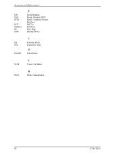
Acronyms and Abbreviations S/N SAS SCSI SCT SelfTest SP SPM S Serial/Number Serial Attached SCSI Small Computer System Interface SeCTor Self Test Save Page SPindle Motor TB TPI UnitOfl T Transfer Block Tracks Per Inch U Unit Offline VCM V Voice Coil Motor WCE W Write Cache Enable 88 C141-E252
Acronyms and Abbreviations S/N SAS SCSI SCT SelfTest SP SPM S Serial/Number Serial Attached SCSI Small Computer System Interface SeCTor Self Test Save Page SPindle Motor TB TPI UnitOfl T Transfer Block Tracks Per Inch U Unit Offline VCM V Voice Coil Motor WCE W Write Cache Enable 88 C141-E252

Product Manual
Page 94
...diagnosis at time of power-on 58 initial seek operation check 73 initial self-diagnostic 66 installation 55, 56 installation requirement 41 interface connector 51 interface test 68 internal test space 29 L leak magnetic flux 47 limitation of bottom-mounting 45 limitation of side-mounting 45 logical data...70 replacement 56 reporting result of self-diagnostic and error indication 67 reserve and release function 15 responses to operation errors 58 S SAS standard 14 sector format 32 seek test 66 self-diagnostic 65 SEND DIAGNOSTIC command 67 sense data 81 sense data analysis 83 ...
...diagnosis at time of power-on 58 initial seek operation check 73 initial self-diagnostic 66 installation 55, 56 installation requirement 41 interface connector 51 interface test 68 internal test space 29 L leak magnetic flux 47 limitation of bottom-mounting 45 limitation of side-mounting 45 logical data...70 replacement 56 reporting result of self-diagnostic and error indication 67 reserve and release function 15 responses to operation errors 58 S SAS standard 14 sector format 32 seek test 66 self-diagnostic 65 SEND DIAGNOSTIC command 67 sense data 81 sense data analysis 83 ...
