
Product Manual
Page 15
Illustrations Contents Figures Figure 1.1 Figure 1.2 Example of SAS system configuration (Dual port internal cabled environment 18 Example of SAS system configuration (Dual port internal backplane environment 18 Figure 3.1 Figure 3.2 Figure 3.3 Figure 3.4 Figure 3.5 Figure 3.6 Figure 3.7 Figure 3.8 Cylinder configuration 28 Spare ...
Illustrations Contents Figures Figure 1.1 Figure 1.2 Example of SAS system configuration (Dual port internal cabled environment 18 Example of SAS system configuration (Dual port internal backplane environment 18 Figure 3.1 Figure 3.2 Figure 3.3 Figure 3.4 Figure 3.5 Figure 3.6 Figure 3.7 Figure 3.8 Cylinder configuration 28 Spare ...
Product Manual
Page 22
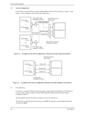
... backplane environment) (1) Port addressing Every device connected with the SAS protocol has a unique address (SAS address). Figure 1.1 Example of SAS system configuration (Dual port internal cabled environment) Figure 1.2 Example of the SAS system configuration. An SAS address consists of 8 bytes as a unique value set for each device. The initiator can implement...
... backplane environment) (1) Port addressing Every device connected with the SAS protocol has a unique address (SAS address). Figure 1.1 Example of SAS system configuration (Dual port internal cabled environment) Figure 1.2 Example of the SAS system configuration. An SAS address consists of 8 bytes as a unique value set for each device. The initiator can implement...

Product Manual
Page 29
... 25 2.1 Hardware Specifications Note: The MTBF is defined as follows. Mishandling by the operator, failures due to bad environmental conditions, power trouble, host system trouble, cable failures, or other failures not caused by a well-trained service mechanic to 60°C.) Even if the HDDs are used intermittently, the longest service life...
... 25 2.1 Hardware Specifications Note: The MTBF is defined as follows. Mishandling by the operator, failures due to bad environmental conditions, power trouble, host system trouble, cable failures, or other failures not caused by a well-trained service mechanic to 60°C.) Even if the HDDs are used intermittently, the longest service life...
Product Manual
Page 61
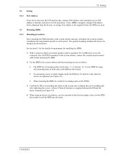
... bottom. • Use mounting screws of requirements for I/O operations. At least 2.5mm of clearance is mounted on the system cabinet, connect the external operator panel cable before the HDDs are used. 5.3 Mounting HDDs 5.3.1 Mounting procedures Since mounting the HDD depends on the HDD that uses the SAS interface has a unique SAS...
... bottom. • Use mounting screws of requirements for I/O operations. At least 2.5mm of clearance is mounted on the system cabinet, connect the external operator panel cable before the HDDs are used. 5.3 Mounting HDDs 5.3.1 Mounting procedures Since mounting the HDD depends on the HDD that uses the SAS interface has a unique SAS...

Product Manual
Page 62
... to confirm that the transfer rate and HDD SAS addresses can respond to the HDD. b) The HDDs do not start by the SAS protocol to cables. b) Check whether the supply voltage is supplied normally. (Measure the voltage at the time of initial operation after the NOTIFY (ENABLE SPINUP) primitive is explained...
... to confirm that the transfer rate and HDD SAS addresses can respond to the HDD. b) The HDDs do not start by the SAS protocol to cables. b) Check whether the supply voltage is supplied normally. (Measure the voltage at the time of initial operation after the NOTIFY (ENABLE SPINUP) primitive is explained...

Product Manual
Page 77
Possible causes include insufficient power capacity, loose cable connection, insufficient timing or insufficient mechanical play, and problems related to the MPU on the PCBA. The interrupt is posted to other systems. If an ...
Possible causes include insufficient power capacity, loose cable connection, insufficient timing or insufficient mechanical play, and problems related to the MPU on the PCBA. The interrupt is posted to other systems. If an ...

Product Manual
Page 79
6.4 Troubleshooting Table 6.2 System-level field troubleshooting Item DC power level Electrical noise System cables System diagnostic test Intermittent or nonfatal errors Recommended work Check that all system cables are connected correctly. For +5V DC, measure the voltage between pin P14 (+12V) of a possible fault. If replacing the HDD does not eliminate the error...
6.4 Troubleshooting Table 6.2 System-level field troubleshooting Item DC power level Electrical noise System cables System diagnostic test Intermittent or nonfatal errors Recommended work Check that all system cables are connected correctly. For +5V DC, measure the voltage between pin P14 (+12V) of a possible fault. If replacing the HDD does not eliminate the error...