

Product Manual
Page 4
... Rev. 24 SCSI Architecture Model-2 (SAM-2) T10/1561D Rev. 14 SCSI Architecture Model-3 (SAM-3) T10/1562D Rev. 05 Serial Attached SCSI (SAS) T10/1601D Rev. 10 Serial Attached SCSI Model-1.1 (SAS 1.1) *1 ANSI = American National Standard Institute In case of conflict between this manual and any packaging part of China This product is...
... Rev. 24 SCSI Architecture Model-2 (SAM-2) T10/1561D Rev. 14 SCSI Architecture Model-3 (SAM-3) T10/1562D Rev. 05 Serial Attached SCSI (SAS) T10/1601D Rev. 10 Serial Attached SCSI Model-1.1 (SAS 1.1) *1 ANSI = American National Standard Institute In case of conflict between this manual and any packaging part of China This product is...

Product Manual
Page 5
...chapter describes the data structure, the addressing method, and the defect management. C141-E252 1 inch hard disk drives with an embedded Serial Attached SCSI (SAS). This manual details the specifications and functions of this manual. This manual is written for users who... for setting device number and operation modes, mounting the disk drive, and confirming drive operation. Chapter 5 Installation This chapter explains how to install the disk drives. Preface This manual describes MBA3300RC, MBA3147RC, and MBA3073RC 3.5 - Chapter 4 Installation Requirements This chapter ...
...chapter describes the data structure, the addressing method, and the defect management. C141-E252 1 inch hard disk drives with an embedded Serial Attached SCSI (SAS). This manual details the specifications and functions of this manual. This manual is written for users who... for setting device number and operation modes, mounting the disk drive, and confirming drive operation. Chapter 5 Installation This chapter explains how to install the disk drives. Preface This manual describes MBA3300RC, MBA3147RC, and MBA3073RC 3.5 - Chapter 4 Installation Requirements This chapter ...

Product Manual
Page 7
... 30 seconds.). 2. When removing the HDD, avoid exposing it . • Dismount the HDD using the drive mounting/dismounting mechanism, etc. of the system. Just in the antistatic case (Fcell) (refer to stop dismounting once when SAS connector breaks off the power. Task Installation Alert message Damage Never remove any labels from the...
... 30 seconds.). 2. When removing the HDD, avoid exposing it . • Dismount the HDD using the drive mounting/dismounting mechanism, etc. of the system. Just in the antistatic case (Fcell) (refer to stop dismounting once when SAS connector breaks off the power. Task Installation Alert message Damage Never remove any labels from the...
Product Manual
Page 9
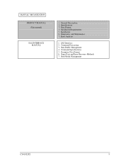
Specifications 3. Installation Requirements 5. Data Buffer Management 4. Command Specifications 5. Parameter Data Format 6. Disk Media Management C141-E252 5 Diagnostics and Maintenance 7. General Description 2. Error Analysis 1. Installation 6. Data Format 4. MANUAL ORGANIZATION PRODUCT MANUAL (This manual) SAS INTERFACE MANUAL 1. SAS Interface 2. Command Processing 3. Sense Data and Error Recovery Methods 7.
Specifications 3. Installation Requirements 5. Data Buffer Management 4. Command Specifications 5. Parameter Data Format 6. Disk Media Management C141-E252 5 Diagnostics and Maintenance 7. General Description 2. Error Analysis 1. Installation 6. Data Format 4. MANUAL ORGANIZATION PRODUCT MANUAL (This manual) SAS INTERFACE MANUAL 1. SAS Interface 2. Command Processing 3. Sense Data and Error Recovery Methods 7.
Product Manual
Page 15
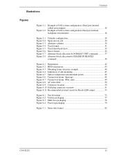
... configuration (Dual port internal cabled environment 18 Example of SAS system configuration (Dual port internal backplane environment 18 Figure 3.1 Figure 3.2 Figure 3.3 Figure 3.4 Figure 3.5 Figure 3.6 Figure 3.7 Figure 3.8 Cylinder configuration 28 Spare ... 4.6 Current waveform (Spin-up 48 Figure 4.7 Current waveform (Max seek 49 Figure 4.8 AC noise filter 50 Figure 4.9 Connector location 50 Figure 4.10 SAS plug connector overview 51 Figure 4.11 Recommended external circuit for Ready LED output 53 Figure 6.1 Figure 6.2 Figure 6.3 Figure 6.4 Test flowchart 72 Unitary packaging ...
... configuration (Dual port internal cabled environment 18 Example of SAS system configuration (Dual port internal backplane environment 18 Figure 3.1 Figure 3.2 Figure 3.3 Figure 3.4 Figure 3.5 Figure 3.6 Figure 3.7 Figure 3.8 Cylinder configuration 28 Spare ... 4.6 Current waveform (Spin-up 48 Figure 4.7 Current waveform (Max seek 49 Figure 4.8 AC noise filter 50 Figure 4.9 Connector location 50 Figure 4.10 SAS plug connector overview 51 Figure 4.11 Recommended external circuit for Ready LED output 53 Figure 6.1 Figure 6.2 Figure 6.3 Figure 6.4 Test flowchart 72 Unitary packaging ...
Product Manual
Page 16
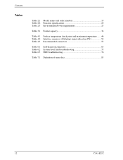
Contents Tables Table 2.1 Model names and order numbers 19 Table 2.2 Function specifications 20 Table 2.3 Environmental/Power requirements 23 Table 3.1 Format capacity 34 Table 4.1 Surface temperature check point and maximum temperature ....... 46 Table 4.2 Interface connector (SAS plug) signal allocation:CN1 52 Table 4.3 Recommended connectors 53 Table 6.1 Self-diagnostic functions 65 Table 6.2 System-level field troubleshooting 75 Table 6.3 HDD troubleshooting 76 Table 7.1 Definition of sense data 83 12 C141-E252
Contents Tables Table 2.1 Model names and order numbers 19 Table 2.2 Function specifications 20 Table 2.3 Environmental/Power requirements 23 Table 3.1 Format capacity 34 Table 4.1 Surface temperature check point and maximum temperature ....... 46 Table 4.2 Interface connector (SAS plug) signal allocation:CN1 52 Table 4.3 Recommended connectors 53 Table 6.1 Self-diagnostic functions 65 Table 6.2 System-level field troubleshooting 75 Table 6.3 HDD troubleshooting 76 Table 7.1 Definition of sense data 83 12 C141-E252

Product Manual
Page 17
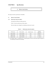
... layers to SCSI command protocols. C141-E252 13 The HDDs are equipped with ANSI T10/1601-D Serial Attached SCSI-1.1 (SAS-1.1), which complies with the 3.5-inch hard disk drive form factor. (2) Environmental Protection The HDDs comply with the Restriction of the use of the MBA3xxxRC. CHAPTER 1 General Description 1.1 ... and configuration of certain Hazardous Substances in electrical and electronic equipment (RoHS) directive issued by European Union (EU). (3) SAS Standard The HDDs are high performance large capacity 3.5-inch hard disk drives with an embedded Serial Attached SCSI...
... layers to SCSI command protocols. C141-E252 13 The HDDs are equipped with ANSI T10/1601-D Serial Attached SCSI-1.1 (SAS-1.1), which complies with the 3.5-inch hard disk drive form factor. (2) Environmental Protection The HDDs comply with the Restriction of the use of the MBA3xxxRC. CHAPTER 1 General Description 1.1 ... and configuration of certain Hazardous Substances in electrical and electronic equipment (RoHS) directive issued by European Union (EU). (3) SAS Standard The HDDs are high performance large capacity 3.5-inch hard disk drives with an embedded Serial Attached SCSI...

Product Manual
Page 18
...When Write Cache is surely terminated with specifying "0" to [64K-1] blocks in a logically continuous data space without waiting for the SAS to support dual SAS port connection. To ensure it, you should ensure that the command is enabled, you turn off the HDDs power. The continuous ... perform continuous read automatically and store (prefetches) the subsequent data blocks into the data buffer (Read-ahead caching). General Description (4) Dual SAS port support The HDDs have two pairs of driver and receiver set (PHY) for completion of write processing to the disk media before ...
...When Write Cache is surely terminated with specifying "0" to [64K-1] blocks in a logically continuous data space without waiting for the SAS to support dual SAS port connection. To ensure it, you should ensure that the command is enabled, you turn off the HDDs power. The continuous ... perform continuous read automatically and store (prefetches) the subsequent data blocks into the data buffer (Read-ahead caching). General Description (4) Dual SAS port support The HDDs have two pairs of driver and receiver set (PHY) for completion of write processing to the disk media before ...
Product Manual
Page 20
... can be obtained from the errors on each partition (constant density recording). This feature easily achieves maintenance and function enhancement of spindle motor Using the SAS primitive or the SCSI command, the host system can start and stop the spindle motor. (18) Diagnosis The HDDs have a diagnostic capability which checks internal...
... can be obtained from the errors on each partition (constant density recording). This feature easily achieves maintenance and function enhancement of spindle motor Using the SAS primitive or the SCSI command, the host system can start and stop the spindle motor. (18) Diagnosis The HDDs have a diagnostic capability which checks internal...

Product Manual
Page 21
... on an actuator and disks on a spindle motor mounted on the ramp when the power is off or the spindle motor is controlled by a direct-drive hall-less DC motor. Resistive) read /write circuit and a controller circuit. (1) Disks The disks have an outer diameter of the actuator arm are ...rotated by a feedback circuit using the counter electromotive current to increase the performance of the SAS controller. C141-E252 17 The heads at the end of 70 mm (2.8 inch). (2) Heads The heads have a disk enclosure (DE) and a printed circuit ...
... on an actuator and disks on a spindle motor mounted on the ramp when the power is off or the spindle motor is controlled by a direct-drive hall-less DC motor. Resistive) read /write circuit and a controller circuit. (1) Disks The disks have an outer diameter of the actuator arm are ...rotated by a feedback circuit using the counter electromotive current to increase the performance of the SAS controller. C141-E252 17 The heads at the end of 70 mm (2.8 inch). (2) Heads The heads have a disk enclosure (DE) and a printed circuit ...
Product Manual
Page 22
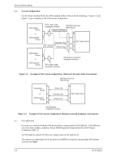
...Point technology. Figure 1.1 and Figure 1.2 give examples of SAS system configuration (Dual port internal backplane environment) (1) Port addressing Every device connected with the SAS protocol has a unique address (SAS address). Figure 1.1 Example of SAS system configuration (Dual port internal cabled environment) Figure 1.2 ... implement an I/O operation on an HDD by using the corresponding SAS address stored by SCSI Primary Command-2 (SPC-2). An SAS address consists of 8 bytes as a unique value set for each device. SAS addresses are in the Name Address Authority (NAA) IEEE Registered...
...Point technology. Figure 1.1 and Figure 1.2 give examples of SAS system configuration (Dual port internal backplane environment) (1) Port addressing Every device connected with the SAS protocol has a unique address (SAS address). Figure 1.1 Example of SAS system configuration (Dual port internal cabled environment) Figure 1.2 ... implement an I/O operation on an HDD by using the corresponding SAS address stored by SCSI Primary Command-2 (SPC-2). An SAS address consists of 8 bytes as a unique value set for each device. SAS addresses are in the Name Address Authority (NAA) IEEE Registered...
Product Manual
Page 23
... environment and formatting. Table 2.1 Model names and order numbers Model name Order number Interface type Capacity (user area) MBA3300RC CA06778-B400 SAS 300 GB (*) MBA3147RC CA06778-B200 SAS 147 GB (*) MBA3073RC CA06778-B100 SAS 73.5 GB (*) (*) One gigabyte (GB) = one billion bytes; accessible capacity will be changed by reinitializing with the user's system. Table 2.1 lists the model name and...
... environment and formatting. Table 2.1 Model names and order numbers Model name Order number Interface type Capacity (user area) MBA3300RC CA06778-B400 SAS 300 GB (*) MBA3147RC CA06778-B200 SAS 147 GB (*) MBA3073RC CA06778-B100 SAS 73.5 GB (*) (*) One gigabyte (GB) = one billion bytes; accessible capacity will be changed by reinitializing with the user's system. Table 2.1 lists the model name and...
Product Manual
Page 24
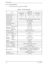
... Power consumption (*5) Data transfer Internal rate (*6) External Logical data block length Related standards Data buffer Acoustic noise (Idle) Specification MBA3300RC MBA3147RC MBA3073RC 300 GB (*2) 147 GB (*2) 73.5 GB (*2) 4 2 1 8 4 2 82604 cyl typ. (standard format including the alternate cylinder) 60/62 MEEPRML 124.7 Gbit/inch2... 30 s typ. 26.1 mm max. 101.6 mm ± 0.25mm 147.0 mm max. 0.8 kg max. 12.36 W typ. 188 MB/s (standard format, most outer) 1.5 Gbps, 3 Gbps 512 to 528 byte (fixed length) (*7) SAS (T10/1562D Rev. 05), SAS1.1 (T10/1601D Rev. 07), SAM...
... Power consumption (*5) Data transfer Internal rate (*6) External Logical data block length Related standards Data buffer Acoustic noise (Idle) Specification MBA3300RC MBA3147RC MBA3073RC 300 GB (*2) 147 GB (*2) 73.5 GB (*2) 4 2 1 8 4 2 82604 cyl typ. (standard format including the alternate cylinder) 60/62 MEEPRML 124.7 Gbit/inch2... 30 s typ. 26.1 mm max. 101.6 mm ± 0.25mm 147.0 mm max. 0.8 kg max. 12.36 W typ. 188 MB/s (standard format, most outer) 1.5 Gbps, 3 Gbps 512 to 528 byte (fixed length) (*7) SAS (T10/1562D Rev. 05), SAS1.1 (T10/1601D Rev. 07), SAM...

Product Manual
Page 33
... data block and the number of logical data blocks to each cylinder required in the user space in the user space with 0 is also called SA space. Always 10 cylinders are recorded. • Defect list (P list and G list) • MODE SELECT parameter (saved value) • Statistical information (log data) • Controller...
... data block and the number of logical data blocks to each cylinder required in the user space in the user space with 0 is also called SA space. Always 10 cylinders are recorded. • Defect list (P list and G list) • MODE SELECT parameter (saved value) • Statistical information (log data) • Controller...

Product Manual
Page 40
... blocks in the user space, as long as the G list. The logical data block is allocated to Subsection 6.3.2 "Auto alternate block allocation processing" of the SAS INTERFACE MANUAL for details. This information is recorded in "alternate cylinders". Refer to the next physically continued sectors after the above sector slip treatment is...
... blocks in the user space, as long as the G list. The logical data block is allocated to Subsection 6.3.2 "Auto alternate block allocation processing" of the SAS INTERFACE MANUAL for details. This information is recorded in "alternate cylinders". Refer to the next physically continued sectors after the above sector slip treatment is...

Product Manual
Page 43
... the same as described below: Type 1 (Reassignment of the error LBA, repeats the primary media check up to the G list, another alternate block is allocated.) c) SA and defect map update processing (on the defective data block detected during WRITE command processing as with error. WRITE at write operation If AWRE flag...
... the same as described below: Type 1 (Reassignment of the error LBA, repeats the primary media check up to the G list, another alternate block is allocated.) c) SA and defect map update processing (on the defective data block detected during WRITE command processing as with error. WRITE at write operation If AWRE flag...
Product Manual
Page 55
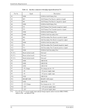
4.3 Connection Requirements 4.3.2 Interface connector Figure 4.10 shows the SAS type interface connector (SAS plug) overview. Top view Bottom view Top view Bottom view Figure 4.10 SAS plug connector overview C141-E252 51 Table 4.2 lists the signal allocation of the SAS plug on the HDDs.
4.3 Connection Requirements 4.3.2 Interface connector Figure 4.10 shows the SAS type interface connector (SAS plug) overview. Top view Bottom view Top view Bottom view Figure 4.10 SAS plug connector overview C141-E252 51 Table 4.2 lists the signal allocation of the SAS plug on the HDDs.
Product Manual
Page 56
... Port Transmit (positive) signal S14 GND GND for SAS Secondary Port P1 (*1) Reserved (not used) Not used P2 (*1) Reserved (not used) Not used P3 (*1) Reserved (not used) Not used on MBA3300RC, MBA3147RC, and MBA3073RC. 52 C141-E252 Signal Description S1 GND GND for +12V P14 +12V +12V power supply input P15 (*1) +12V...
... Port Transmit (positive) signal S14 GND GND for SAS Secondary Port P1 (*1) Reserved (not used) Not used P2 (*1) Reserved (not used) Not used P3 (*1) Reserved (not used) Not used on MBA3300RC, MBA3147RC, and MBA3073RC. 52 C141-E252 Signal Description S1 GND GND for +12V P14 +12V +12V power supply input P15 (*1) +12V...
Product Manual
Page 61
... the HDD by using an electric screwdriver, use the screwdriver that does not apply a force on the HDD that uses the SAS interface has a unique SAS address, and commands use an SAS address to damage parts on the PCBA. 3) Confirm the DE is not touching the frame on the system side excluding the... ±0.5 mm when the screws are shown below. 5.2 Setting 5.2 Setting 5.2.1 Port Address Every device that would exceed the HDD specifications. Every HDD is assigned a unique SAS address before shipment from the factory, so setting of requirements for I/O operations.
... the HDD by using an electric screwdriver, use the screwdriver that does not apply a force on the HDD that uses the SAS interface has a unique SAS address, and commands use an SAS address to damage parts on the PCBA. 3) Confirm the DE is not touching the frame on the system side excluding the... ±0.5 mm when the screws are shown below. 5.2 Setting 5.2 Setting 5.2.1 Port Address Every device that would exceed the HDD specifications. Every HDD is assigned a unique SAS address before shipment from the factory, so setting of requirements for I/O operations.

Product Manual
Page 62
...procedure: a) Confirm that data is ready to operate. The following is completed normally, the HDDs start by the SAS protocol to verify that the transfer rate and HDD SAS addresses can be recognized during the LINK RESET sequence. b) Issue the INQUIRY, WRITE BUFFER, and READ BUFFER ...commands to establish synchronization with the connected SAS devices (e.g., the host system). a) The host system instructs the spindle motor to start the LINK RESET sequence defined by sending the NOTIFY...
...procedure: a) Confirm that data is ready to operate. The following is completed normally, the HDDs start by the SAS protocol to verify that the transfer rate and HDD SAS addresses can be recognized during the LINK RESET sequence. b) Issue the INQUIRY, WRITE BUFFER, and READ BUFFER ...commands to establish synchronization with the connected SAS devices (e.g., the host system). a) The host system instructs the spindle motor to start the LINK RESET sequence defined by sending the NOTIFY...
