Manual/User Guide
Page 16
... 5-1 5.1 Physical Interface 5-2 5.1.1 Interface signals 5-2 5.1.2 Signal assignment on the connector 5-3 5.2 Logical Interface 5-6 5.2.1 I/O registers 5-7 5.2.2 Command block registers 5-8 5.2.3 Control block registers 5-13 5.3 Host Commands 5-13 5.3.1 Command code and parameters 5-14 5.3.2 Command descriptions 5-16 5.3.3 Error posting 5-77 5.4 Command Protocol 5-79 5.4.1 Data transferring commands from device to host 5-79 5.4.2 Data transferring commands from host to device...
... 5-1 5.1 Physical Interface 5-2 5.1.1 Interface signals 5-2 5.1.2 Signal assignment on the connector 5-3 5.2 Logical Interface 5-6 5.2.1 I/O registers 5-7 5.2.2 Command block registers 5-8 5.2.3 Control block registers 5-13 5.3 Host Commands 5-13 5.3.1 Command code and parameters 5-14 5.3.2 Command descriptions 5-16 5.3.3 Error posting 5-77 5.4 Command Protocol 5-79 5.4.1 Data transferring commands from device to host 5-79 5.4.2 Data transferring commands from host to device...
Manual/User Guide
Page 18
... 6-1 Glossary 6.1 Device Response to the Reset 6-2 6.1.1 Response to power-on 6-2 6.1.2 Response to hardware reset 6-4 6.1.3 Response to software reset 6-5 6.1.4 Response to diagnostic command 6-6 6.2 Address Translation 6-7 6.2.1 Default parameters 6-7 6.2.2 Logical address 6-8 6.3 Power Save 6-9 6.3.1 Power save mode 6.3.2 Power commands 6-9 6-11 6.4 Defect Management 6-11 6.4.1 Spare area 6-12 6.4.2 Alternating defective sectors 6-12 6.5 Read-Ahead Cache 6-14 6.5.1 Data...
... 6-1 Glossary 6.1 Device Response to the Reset 6-2 6.1.1 Response to power-on 6-2 6.1.2 Response to hardware reset 6-4 6.1.3 Response to software reset 6-5 6.1.4 Response to diagnostic command 6-6 6.2 Address Translation 6-7 6.2.1 Default parameters 6-7 6.2.2 Logical address 6-8 6.3 Power Save 6-9 6.3.1 Power save mode 6.3.2 Power commands 6-9 6-11 6.4 Defect Management 6-11 6.4.1 Spare area 6-12 6.4.2 Alternating defective sectors 6-12 6.5 Read-Ahead Cache 6-14 6.5.1 Data...
Manual/User Guide
Page 21
... 4-9 Table 4.2 Write precompensation algorithm 4-10 Table 5.1 Signal assignment on the interface connector 5-3 Table 5.2 I/O registers 5-7 Table 5.3 Command code and parameters 5-14 Table 5.4 Information to be read by IDENTIFY DEVICE command 5- 32 Table 5.5 Features register values and settable modes 5-40 Table 5.6 Diagnostic code... between combination of Identifier and Security level, and operation of the lock function 5-74 Table 5.15 Command code and parameters 5-77 Table 5.16 Parallel generation equation of CRC polynomial 5-99 Table 5.17 Recommended series termination for Ultra DMA 5-100...
... 4-9 Table 4.2 Write precompensation algorithm 4-10 Table 5.1 Signal assignment on the interface connector 5-3 Table 5.2 I/O registers 5-7 Table 5.3 Command code and parameters 5-14 Table 5.4 Information to be read by IDENTIFY DEVICE command 5- 32 Table 5.5 Features register values and settable modes 5-40 Table 5.6 Diagnostic code... between combination of Identifier and Security level, and operation of the lock function 5-74 Table 5.15 Command code and parameters 5-77 Table 5.16 Parallel generation equation of CRC polynomial 5-99 Table 5.17 Recommended series termination for Ultra DMA 5-100...

Manual/User Guide
Page 79
... each signal wire. When there is controlled by the DIOR and DIOW signals. When the host system specifies the LBA mode by the INITIALIZE DEVICE PARAMETER command, the sector LBA address is performed, IOCS16-, CS0- LBA0 = [Cylinder 0, Head 0, Sector 1] Even if the host system changes the assignment of the CHS mode...
... each signal wire. When there is controlled by the DIOR and DIOW signals. When the host system specifies the LBA mode by the INITIALIZE DEVICE PARAMETER command, the sector LBA address is performed, IOCS16-, CS0- LBA0 = [Cylinder 0, Head 0, Sector 1] Even if the host system changes the assignment of the CHS mode...
Manual/User Guide
Page 82
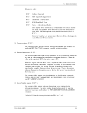
Error register of data to X'05'). INITIALIZE DEVICE PARAMETERS, SET FEATURES, IDLE, STANDBY and SET MULTIPLE MODE. (5) Sector Number register (X'1F3') The contents of this indicates that the data has not been transferred due ... indicates the starting sector number for the following commands; When this register indicates X'00' at the completion of sectors per track defined by INITIALIZE DEVICE PARAMETERS command. If the command is , this register indicates LBA bits 7 to a command. The sector number should be transferred in this register has other definition for...
Error register of data to X'05'). INITIALIZE DEVICE PARAMETERS, SET FEATURES, IDLE, STANDBY and SET MULTIPLE MODE. (5) Sector Number register (X'1F3') The contents of this indicates that the data has not been transferred due ... indicates the starting sector number for the following commands; When this register indicates X'00' at the completion of sectors per track defined by INITIALIZE DEVICE PARAMETERS command. If the command is , this register indicates LBA bits 7 to a command. The sector number should be transferred in this register has other definition for...
Manual/User Guide
Page 83
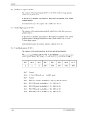
Bit 2: HS2 CHS mode head address 2 (22). When executing INITIALIZE DEVICE PARAMETERS command, the contents of this register indicates high-order 8 bits of the disk-access start cylinder address. Bit 5: Unused - Bit 1: HS1 CHS mode head address 1 (...
Bit 2: HS2 CHS mode head address 2 (22). When executing INITIALIZE DEVICE PARAMETERS command, the contents of this register indicates high-order 8 bits of the disk-access start cylinder address. Bit 5: Unused - Bit 1: HS1 CHS mode head address 1 (...
Manual/User Guide
Page 85
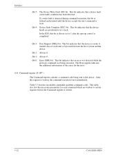
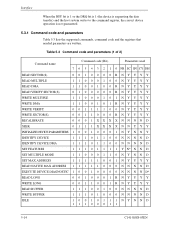
... or byte unit between the host system and the device. - Table 5.3 lists the executable commands and their command codes. This table also lists the neccesary parameters for the error. (10) Command register (X'1F7') The Command register contains a command code being executed. Bit 5: The Device Write Fault (DF) bit. Interface - Bit 2: Always...
... or byte unit between the host system and the device. - Table 5.3 lists the executable commands and their command codes. This table also lists the neccesary parameters for the error. (10) Command register (X'1F7') The Command register contains a command code being executed. Bit 5: The Device Write Fault (DF) bit. Interface - Bit 2: Always...
Manual/User Guide
Page 86
... (INTRQ signal) from the Status register is that a read of this bit is set, the device is not required to the device by writing necessary parameters in related registers in the command block and writing a command code in the busy status).
... (INTRQ signal) from the Status register is that a read of this bit is set, the device is not required to the device by writing necessary parameters in related registers in the command block and writing a command code in the busy status).
Manual/User Guide
Page 87
... DMA 1 1 0 0 1 0 0 RNYYYY READ VERIFY SECTOR(S) 0 1 0 0 0 0 0 RNYYYY WRITE MULTIPLE WRITE DMA WRITE VERIFY WRITE SECTOR(S) RECALIBRATE SEEK 1 1 0 0 0 1 0 1 NYYYY 1 1 0 0 1 0 1 RNYYYY 0 0 1 1 1 1 0 0 NYYYY 0 0 1 1 0 0 0 RNYYYY 0 0 0 1 XXXXNNNND 0 1 1 1 XXXXNNYYY INITIALIZE DEVICE PARAMETERS 1 0 0 1 0 0 0 1 N Y N N Y IDENTIFY DEVICE 1 1 1 0 1 1 0 0 NNNND IDENTIFY DEVICE DMA 1 1 1 0 1 1 0 0 NNNND SET FEATURES 1 1 1 0 1 1 1 1 Y N* N N D SET MULTIPLE MODE 1 1 0 0 0 1 1 0 NYNND SET MAX ADDRESS 1 1 1 1 1 0 0 1 NYYYY READ NATIVE MAX ADDRESS 1 1 1 1 1 0 0 0 N N N N D EXECUTE DEVICE...
... DMA 1 1 0 0 1 0 0 RNYYYY READ VERIFY SECTOR(S) 0 1 0 0 0 0 0 RNYYYY WRITE MULTIPLE WRITE DMA WRITE VERIFY WRITE SECTOR(S) RECALIBRATE SEEK 1 1 0 0 0 1 0 1 NYYYY 1 1 0 0 1 0 1 RNYYYY 0 0 1 1 1 1 0 0 NYYYY 0 0 1 1 0 0 0 RNYYYY 0 0 0 1 XXXXNNNND 0 1 1 1 XXXXNNYYY INITIALIZE DEVICE PARAMETERS 1 0 0 1 0 0 0 1 N Y N N Y IDENTIFY DEVICE 1 1 1 0 1 1 0 0 NNNND IDENTIFY DEVICE DMA 1 1 1 0 1 1 0 0 NNNND SET FEATURES 1 1 1 0 1 1 1 1 Y N* N N D SET MULTIPLE MODE 1 1 0 0 0 1 1 0 NYNND SET MAX ADDRESS 1 1 1 1 1 0 0 1 NYYYY READ NATIVE MAX ADDRESS 1 1 1 1 1 0 0 0 N N N N D EXECUTE DEVICE...

Manual/User Guide
Page 88
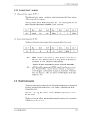
5.3 Host Commands Table 5.3 Command code and parameters (2 of 2) Command name Command code (Bit) Parameters used 7 6 5 4 3 2 1 0 FR SC SN CY DH IDLE IMMEDIATE 1 0 0 1 0 1 0 1 NNNND 11100001 STANDBY 1 0 0 1 0 1 1 0 NYNND 11100010 STANDBY IMMEDIATE 1 0 0 1 0 1 0 0 NNNND 11100000 SLEEP 1 0 0 1 1 0...1 0 0 0 1 NNNND SECURITY UNLOCK 1 1 1 1 0 0 1 0 NNNND FLUSH CACHE 1 1 1 0 0 1 1 1 NNNND Notes: FR: Features Register CY: Cylinder Registers SC: Sector Count Register DH: Drive/Head Register SN: Sector Number Register R: Retry at error 1 = Without retry 0 = With retry Y: Necessary to set...
5.3 Host Commands Table 5.3 Command code and parameters (2 of 2) Command name Command code (Bit) Parameters used 7 6 5 4 3 2 1 0 FR SC SN CY DH IDLE IMMEDIATE 1 0 0 1 0 1 0 1 NNNND 11100001 STANDBY 1 0 0 1 0 1 1 0 NYNND 11100010 STANDBY IMMEDIATE 1 0 0 1 0 1 0 0 NNNND 11100000 SLEEP 1 0 0 1 1 0...1 0 0 0 1 NNNND SECURITY UNLOCK 1 1 1 1 0 0 1 0 NNNND FLUSH CACHE 1 1 1 0 0 1 1 1 NNNND Notes: FR: Features Register CY: Cylinder Registers SC: Sector Count Register DH: Drive/Head Register SN: Sector Number Register R: Retry at error 1 = Without retry 0 = With retry Y: Necessary to set...
Manual/User Guide
Page 89
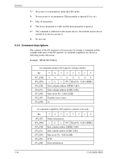
... addressed to the master device, but both the master device and the slave device execute it is set.) N*: May set parameters under the LBA mode. Example: READ SECTOR(S) At command issuance (I/O registers setting contents) Bit 1F7 (CM) H 1F6 (DH) H 1F5 (CH) H 1F4 (CL) H 1F3H(SN) 1F2H(...] / LBA End sector No. / LBA [LSB] X'00' Error information 5-16 C141-E088-03EN X: Do not care 5.3.2 Command descriptions The contents of the I /O registers to set parameters (The parameter is ignored if it .
... addressed to the master device, but both the master device and the slave device execute it is set.) N*: May set parameters under the LBA mode. Example: READ SECTOR(S) At command issuance (I/O registers setting contents) Bit 1F7 (CM) H 1F6 (DH) H 1F5 (CH) H 1F4 (CL) H 1F3H(SN) 1F2H(...] / LBA End sector No. / LBA [LSB] X'00' Error information 5-16 C141-E088-03EN X: Do not care 5.3.2 Command descriptions The contents of the I /O registers to set parameters (The parameter is ignored if it .
Manual/User Guide
Page 103
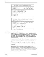
... Cylinder No. [LSB] / LBA Sector No. / LBA [LSB] xx Error information (11) INITIALIZE DEVICE PARAMETERS (X'91') The host system can set by the IDENTIFY DEVICE command. 5-30 C141-E088-03EN An accessible area of the... parameter information by this command terminates normally. Other than X'00' is specified, this ... addressable user sectors (total number of sectors) in the LBA mode is posted. The parameters set the number of sectors per track and the maximum head number (maximum head number is "number...
... Cylinder No. [LSB] / LBA Sector No. / LBA [LSB] xx Error information (11) INITIALIZE DEVICE PARAMETERS (X'91') The host system can set by the IDENTIFY DEVICE command. 5-30 C141-E088-03EN An accessible area of the... parameter information by this command terminates normally. Other than X'00' is specified, this ... addressable user sectors (total number of sectors) in the LBA mode is posted. The parameters set the number of sectors per track and the maximum head number (maximum head number is "number...
Manual/User Guide
Page 104
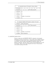
Upon receipt of this command, the drive sets the BSY bit of the parameter words and the meaning in the sector buffer. After that, the host system reads the information out of the Status register, and generates an interrupt. ...The device then sets the DRQ bit of the sector buffer. Table 5.4 shows the arrangements and values of Status register and sets required parameter information in the buffer. 5.3 Host Commands At command issuance (I /O registers contents to read ) 1F7H(ST) 1F6H(DH) 1F5H(CH) 1F4 (CL) H 1F3H(SN) 1F2 (SC...
Upon receipt of this command, the drive sets the BSY bit of the parameter words and the meaning in the sector buffer. After that, the host system reads the information out of the Status register, and generates an interrupt. ...The device then sets the DRQ bit of the sector buffer. Table 5.4 shows the arrangements and values of Status register and sets required parameter information in the buffer. 5.3 Host Commands At command issuance (I /O registers contents to read ) 1F7H(ST) 1F6H(DH) 1F5H(CH) 1F4 (CL) H 1F3H(SN) 1F2 (SC...

Manual/User Guide
Page 113
Then, the device clears the BSY bit, and generates an interrupt. Table 5.5 Features register values and settable modes Features Register Drive operation mode X'02' X'03' X'05' X'55' X'66' X'82' X'85' X'AA' X'BB' X'CC' Enables the write cache function. Disables the write cache function. ... Features register for READ LONG and WRITE LONG commands. Disables the reverting to power-on the contents of the Status register and saves the parameters in the Features register. Disables the advanced power management function. Upon receipt of this command, the device sets the BSY bit of the ...
Then, the device clears the BSY bit, and generates an interrupt. Table 5.5 Features register values and settable modes Features Register Drive operation mode X'02' X'03' X'05' X'55' X'66' X'82' X'85' X'AA' X'BB' X'CC' Enables the write cache function. Disables the write cache function. ... Features register for READ LONG and WRITE LONG commands. Disables the reverting to power-on the contents of the Status register and saves the parameters in the Features register. Disables the advanced power management function. Upon receipt of this command, the device sets the BSY bit of the ...

Manual/User Guide
Page 116
... disabled. The mode established before software reset is retained if disable default (Features Reg. = 66h setting) has been defined by the SET FEATURES command. The parameters for the IDENTIFY DEVICE command. If disable default has not been defined after hardware reset, the READ MULTIPLE and WRITE MULTIPLE command operation are disabled...
... disabled. The mode established before software reset is retained if disable default (Features Reg. = 66h setting) has been defined by the SET FEATURES command. The parameters for the IDENTIFY DEVICE command. If disable default has not been defined after hardware reset, the READ MULTIPLE and WRITE MULTIPLE command operation are disabled...
Manual/User Guide
Page 150
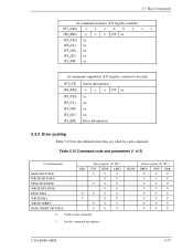
Table 5.15 Command code and parameters (1 of 2) Command name READ SECTOR(S) WRITE SECTOR(S) READ MULTIPLE WRITE MULTIPLE READ DMA WRITE DMA WRITE VERIFY READ VERIFY SECTOR(S) ICRC V V Error register (X'1F1') UNC ...
Table 5.15 Command code and parameters (1 of 2) Command name READ SECTOR(S) WRITE SECTOR(S) READ MULTIPLE WRITE MULTIPLE READ DMA WRITE DMA WRITE VERIFY READ VERIFY SECTOR(S) ICRC V V Error register (X'1F1') UNC ...

Manual/User Guide
Page 151
Interface Table 5.15 Command code and parameters (2 of 2) Command name RECALIBRATE SEEK INITIALIZE DEVICE PARAMETERS IDENTIFY DEVICE IDENTIFY DEVICE DMA SET FEATURES SET MULTIPLE MODE SET MAX ADDRESS READ NATIVE MAX ADDRESS EXECUTE DEVICE DIAGNOSTIC READ LONG WRITE LONG READ ...
Interface Table 5.15 Command code and parameters (2 of 2) Command name RECALIBRATE SEEK INITIALIZE DEVICE PARAMETERS IDENTIFY DEVICE IDENTIFY DEVICE DMA SET FEATURES SET MULTIPLE MODE SET MAX ADDRESS READ NATIVE MAX ADDRESS EXECUTE DEVICE DIAGNOSTIC READ LONG WRITE LONG READ ...
Manual/User Guide
Page 152
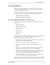
... The host should confirm that the BSY bit of the Status register of the device is 0. • EXECUTE DEVICE DIAGNOSTIC • INITIALIZE DEVICE PARAMETERS 5.4.1 Data transferring commands from device to host The execution of the following commands can be executed even if DRDY bit is 0 prior to issue ...a command. c) The device sets the BSY bit of another sector is determined for each host. In response to 0. f) The drive clears DRQ bit to the Status register being read, the device negates the INTRQ signal. b) The host writes a command code to the Features, Sector ...
... The host should confirm that the BSY bit of the Status register of the device is 0. • EXECUTE DEVICE DIAGNOSTIC • INITIALIZE DEVICE PARAMETERS 5.4.1 Data transferring commands from device to host The execution of the following commands can be executed even if DRDY bit is 0 prior to issue ...a command. c) The device sets the BSY bit of another sector is determined for each host. In response to 0. f) The drive clears DRQ bit to the Status register being read, the device negates the INTRQ signal. b) The host writes a command code to the Features, Sector ...
Manual/User Guide
Page 155
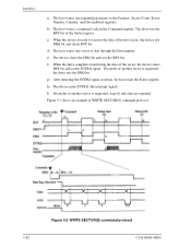
... of the sector, the device clears BSY bit and asserts INTRQ signal. f) When the drive completes transferring the data of data through the Data register. I) If transfer of another sector is requested, the drive sets the DRQ bit. c) When the device is requested, steps d) and after are repeated... WRITE SECTOR(S) command protocol 5-82 C141-E088-03EN Interface a) The host writes any required parameters to receive the data of the first sector, the device sets DRQ bit and clears BSY bit. The drive sets the BSY bit of WRITE SECTOR(S) command protocol. b) The host writes a command code...
... of the sector, the device clears BSY bit and asserts INTRQ signal. f) When the drive completes transferring the data of data through the Data register. I) If transfer of another sector is requested, the drive sets the DRQ bit. c) When the device is requested, steps d) and after are repeated... WRITE SECTOR(S) command protocol 5-82 C141-E088-03EN Interface a) The host writes any required parameters to receive the data of the first sector, the device sets DRQ bit and clears BSY bit. The drive sets the BSY bit of WRITE SECTOR(S) command protocol. b) The host writes a command code...
Manual/User Guide
Page 156
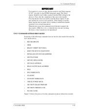
When the host issues the command even if the drive requests the data transfer (DRQ bit is set), or when the host executes resetting, the device correct operation is not assured guaranteed. C141-E088-03EN 5-... not involve data transfer between the host and the device. • RECABLIBRATE • SEEK • READY VERIFY SECTOR(S) • EXECUTE DEVICE DIAGNOSTIC • INITIALIZE DEVICE PARAMETERS • SET FEATURES • SET MULTIPLE MODE • SET MAX ADDRESS • READ NATIVE MAX ADDRESS • IDLE • IDLE IMMEDIATE • STANDBY • STANDBY...
When the host issues the command even if the drive requests the data transfer (DRQ bit is set), or when the host executes resetting, the device correct operation is not assured guaranteed. C141-E088-03EN 5-... not involve data transfer between the host and the device. • RECABLIBRATE • SEEK • READY VERIFY SECTOR(S) • EXECUTE DEVICE DIAGNOSTIC • INITIALIZE DEVICE PARAMETERS • SET FEATURES • SET MULTIPLE MODE • SET MAX ADDRESS • READ NATIVE MAX ADDRESS • IDLE • IDLE IMMEDIATE • STANDBY • STANDBY...