Manual/User Guide
Page 15
... Conditions 3-1 3.1 Dimensions 3-2 3.2 Mounting 3-4 3.3 Cable Connections 3-9 3.3.1 Device connector 3-9 3.3.2 Cable connector specifications 3-10 3.3.3 Device connection 3-10 3.3.4 Power supply connector (CN1) 3-11 3.4 Jumper Settings 3-11 3.4.1 Location of setting jumpers 3-11 3.4.2 Factory default setting 3-12 3.4.3 Master drive-slave drive setting 3-12 3.4.4 CSEL setting 3-13 CHAPTER 4 Theory of Device Operation 4-1 4.1 Outline 4-2 4.2 Subassemblies 4-2 4.2.1 Disk 4-2 4.2.2 Head 4-2 4.2.3 Spindle 4-3 4.2.4 Actuator 4-3 4.2.5 Air filter 4-3 4.3 Circuit...
... Conditions 3-1 3.1 Dimensions 3-2 3.2 Mounting 3-4 3.3 Cable Connections 3-9 3.3.1 Device connector 3-9 3.3.2 Cable connector specifications 3-10 3.3.3 Device connection 3-10 3.3.4 Power supply connector (CN1) 3-11 3.4 Jumper Settings 3-11 3.4.1 Location of setting jumpers 3-11 3.4.2 Factory default setting 3-12 3.4.3 Master drive-slave drive setting 3-12 3.4.4 CSEL setting 3-13 CHAPTER 4 Theory of Device Operation 4-1 4.1 Outline 4-2 4.2 Subassemblies 4-2 4.2.1 Disk 4-2 4.2.2 Head 4-2 4.2.3 Spindle 4-3 4.2.4 Actuator 4-3 4.2.5 Air filter 4-3 4.3 Circuit...

Manual/User Guide
Page 19
...drives configuration 2-4 Figure 3.1 Dimensions (MHJ/MHK series) 3-2 Figure 3.2 Orientation (Sample: MHJ2181AT) 3-4 Figure 3.3 Mounting frame structure 3-5 Figure 3.4 Location of breather 3-6 Figure 3.5 Surface temperature measurement points (Sample: MHJ2181AT) 3-7 Figure 3.6 Service area (Sample: MHJ2181AT) 3-8 Figure 3.7 Connector locations (Sample: MHJ2181AT) 3-9 Figure 3.8 Cable connections 3-10 Figure 3.9 Power supply connector pins (CN1) 3-11 Figure 3.10 Jumper... location 3-11 Figure 3.11 Factory default setting 3-12 Figure 3.12 Jumper setting of master or slave ...
...drives configuration 2-4 Figure 3.1 Dimensions (MHJ/MHK series) 3-2 Figure 3.2 Orientation (Sample: MHJ2181AT) 3-4 Figure 3.3 Mounting frame structure 3-5 Figure 3.4 Location of breather 3-6 Figure 3.5 Surface temperature measurement points (Sample: MHJ2181AT) 3-7 Figure 3.6 Service area (Sample: MHJ2181AT) 3-8 Figure 3.7 Connector locations (Sample: MHJ2181AT) 3-9 Figure 3.8 Cable connections 3-10 Figure 3.9 Power supply connector pins (CN1) 3-11 Figure 3.10 Jumper... location 3-11 Figure 3.11 Factory default setting 3-12 Figure 3.12 Jumper setting of master or slave ...

Manual/User Guide
Page 38
CHAPTER 3 Installation Conditions 3.1 Dimensions 3.2 Mounting 3.3 Cable Connections 3.4 Jumper Settings This chapter gives the external dimensions, installation conditions, surface temperature conditions, cable connections, and switch settings of the hard disk drives. C141-E088-03EN 3-1
CHAPTER 3 Installation Conditions 3.1 Dimensions 3.2 Mounting 3.3 Cable Connections 3.4 Jumper Settings This chapter gives the external dimensions, installation conditions, surface temperature conditions, cable connections, and switch settings of the hard disk drives. C141-E088-03EN 3-1
Manual/User Guide
Page 48
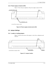
Figure 3.10 Jumper location C141-E088-03EN 3-11 3.4 Jumper Settings 3.3.4 Power supply connector (CN1) Figure 3.9 shows the pin assignment of the jumpers to select drive configuration and functions. Figure 3.9 Power supply connector pins (CN1) 3.4 Jumper Settings 3.4.1 Location of setting jumpers Figure 3.10 shows the location of the power supply connector (CN1).
Figure 3.10 Jumper location C141-E088-03EN 3-11 3.4 Jumper Settings 3.3.4 Power supply connector (CN1) Figure 3.9 shows the pin assignment of the jumpers to select drive configuration and functions. Figure 3.9 Power supply connector pins (CN1) 3.4 Jumper Settings 3.4.1 Location of setting jumpers Figure 3.10 shows the location of the power supply connector (CN1).

Manual/User Guide
Page 49
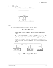
Open Figure 3.11 Factory default setting 3.4.3 Master drive-slave drive setting Master device (device #0) or slave device (device #1) is selected. Open 1 CA 2 DB Open (a) Master drive 1 CA Open Short 2 DB (b) Slave drive Figure 3.12 Jumper setting of master or slave device Note: Pins A and C should be open. 3-12 C141-E088-03EN Installation Conditions 3.4.2 Factory default setting Figure 3.11 shows the default setting position at the factory.
Open Figure 3.11 Factory default setting 3.4.3 Master drive-slave drive setting Master device (device #0) or slave device (device #1) is selected. Open 1 CA 2 DB Open (a) Master drive 1 CA Open Short 2 DB (b) Slave drive Figure 3.12 Jumper setting of master or slave device Note: Pins A and C should be open. 3-12 C141-E088-03EN Installation Conditions 3.4.2 Factory default setting Figure 3.11 shows the default setting position at the factory.
Manual/User Guide
Page 50
... the master device to the CSEL Line (conducer) of Cable Select C141-E088-03EN 3-13 3.4.4 CSEL setting Figure 3.13 shows the cable select (CSEL) setting. 3.4 Jumper Settings Open 1 CA 2 DB Short Note: The CSEL setting is set to high level. The device is set to low level. Figure 3.13 CSEL setting...
... the master device to the CSEL Line (conducer) of Cable Select C141-E088-03EN 3-13 3.4.4 CSEL setting Figure 3.13 shows the cable select (CSEL) setting. 3.4 Jumper Settings Open 1 CA 2 DB Short Note: The CSEL setting is set to high level. The device is set to low level. Figure 3.13 CSEL setting...
Manual/User Guide
Page 111
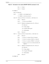
... 0 = '1': Mode 0 *15 WORD 93 Bits 15-14: Reserved Bit 13: '1' = CBLID- was not detected in the selfdiagnosis. of Device 1 (slave drive), a valid value is a level lower than VIH. '0' = CBLID- Bit 3: '1' = Device 0, an error was detected. Bit 2, 1: Method for deciding ...Bits 7-0: In the case of Device 0. '00' = Reserved '01' = Using a jumper. '10' = Using the CSEL signal. '11' = Other method. Bit 12: Reserved Bit 11: '1' = Device asserts PDIAG-. of Device 0 (master drive), a valid value is selected, Device 0 responds. Bit 4: '1' = Device 0, assertion...
... 0 = '1': Mode 0 *15 WORD 93 Bits 15-14: Reserved Bit 13: '1' = CBLID- was not detected in the selfdiagnosis. of Device 1 (slave drive), a valid value is a level lower than VIH. '0' = CBLID- Bit 3: '1' = Device 0, an error was detected. Bit 2, 1: Method for deciding ...Bits 7-0: In the case of Device 0. '00' = Reserved '01' = Using a jumper. '10' = Using the CSEL signal. '11' = Other method. Bit 12: Reserved Bit 11: '1' = Device asserts PDIAG-. of Device 0 (master drive), a valid value is selected, Device 0 responds. Bit 4: '1' = Device 0, assertion...

Manual/User Guide
Page 221
... PARAMETERS 5-30 Inner guard band 4-18 Input voltage 1-5 Installation condition 3-1 Insurance failure threshold 5-66 Interface 1-3, 5-1 Interface signal 5-2 Invalidating caching data 6-15 J Jumper location 3-11 Jumper setting 3-11 L Large capacity 1-2 LBA mode 6-9 Limitation of mounting 3-5 Logical address 6-8 Logical interface 5-6 M Master 1-3 Master drive setting 3-12 Master password 5-74 Mean time between failures 1-9 C141-E088-03EN
... PARAMETERS 5-30 Inner guard band 4-18 Input voltage 1-5 Installation condition 3-1 Insurance failure threshold 5-66 Interface 1-3, 5-1 Interface signal 5-2 Invalidating caching data 6-15 J Jumper location 3-11 Jumper setting 3-11 L Large capacity 1-2 LBA mode 6-9 Limitation of mounting 3-5 Logical address 6-8 Logical interface 5-6 M Master 1-3 Master drive setting 3-12 Master password 5-74 Mean time between failures 1-9 C141-E088-03EN

