
Manual/User Guide
Page 4
...) was changed . - Order No. and DMACK- signals are added. - was altered. - C141-E104-03EN SET MAX commands are changed . - Table 5.17 03 2000-12-13 - Specification (Number of Sections for DIOR-, DIOW- Table 1.1 - Revision History Edition Date Revised section (*1) (Added/Deleted/Altered) 01 2000-02-15 - 02 2000-09...
...) was changed . - Order No. and DMACK- signals are added. - was altered. - C141-E104-03EN SET MAX commands are changed . - Table 5.17 03 2000-12-13 - Specification (Number of Sections for DIOR-, DIOW- Table 1.1 - Revision History Edition Date Revised section (*1) (Added/Deleted/Altered) 01 2000-02-15 - 02 2000-09...

Manual/User Guide
Page 6
...MHL Series and MHM Series and the configuration of the systems in controller that the reader has a basic knowledge of hard disk drives and their implementations in computer systems. This manual consists of seven chapters and sections explaining the special terminology and abbreviations ... manual describes the MHL Series and MHM Series, 2.5-inch hard disk drives. CHAPTER 6 Operations This chapter describes the operations of the MHL Series and MHM Series. CHAPTER 5 Interface This chapter describes the interface specifications of the MHL Series and MHM Series. This manual describes...
...MHL Series and MHM Series and the configuration of the systems in controller that the reader has a basic knowledge of hard disk drives and their implementations in computer systems. This manual consists of seven chapters and sections explaining the special terminology and abbreviations ... manual describes the MHL Series and MHM Series, 2.5-inch hard disk drives. CHAPTER 6 Operations This chapter describes the operations of the MHL Series and MHM Series. CHAPTER 5 Interface This chapter describes the interface specifications of the MHL Series and MHM Series. This manual describes...

Manual/User Guide
Page 15
Contents CHAPTER 3 Installation Conditions 3-1 3.1 Dimensions 3-2 3.2 Mounting 3-4 3.3 Cable Connections 3-10 3.3.1 Device connector 3-10 3.3.2 Cable connector specifications 3-11 3.3.3 Device connection 3-11 3.3.4 Power supply connector (CN1) 3-12 3.4 Jumper Settings 3-12 3.4.1 Location of setting jumpers 3-12 3.4.2 Factory default setting 3-13 3.4.3 Master drive-slave drive setting 3-13 3.4.4 CSEL setting 3-14 CHAPTER 4 Theory of Device Operation 4-1 4.1 Outline 4-2 4.2 Subassemblies 4-2 4.2.1 Disk 4-2 4.2.2 Head...
Contents CHAPTER 3 Installation Conditions 3-1 3.1 Dimensions 3-2 3.2 Mounting 3-4 3.3 Cable Connections 3-10 3.3.1 Device connector 3-10 3.3.2 Cable connector specifications 3-11 3.3.3 Device connection 3-11 3.3.4 Power supply connector (CN1) 3-12 3.4 Jumper Settings 3-12 3.4.1 Location of setting jumpers 3-12 3.4.2 Factory default setting 3-13 3.4.3 Master drive-slave drive setting 3-13 3.4.4 CSEL setting 3-14 CHAPTER 4 Theory of Device Operation 4-1 4.1 Outline 4-2 4.2 Subassemblies 4-2 4.2.1 Disk 4-2 4.2.2 Head...
Manual/User Guide
Page 20
...DMA data out burst 5-118 Figure 5.19 Device pausing an Ultra DMA data out burst 5-119 Figure 5.20 Host terminating an Ultra DMA data out burst 5-120 Figure 5.21 Device terminating an Ultra DMA data out...13 Figure 6.9 Data buffer configuration 6-14 Table 1.1 Table 1.2 Table 1.3 Table 1.4 Table 1.5 Table 1.6 Specifications 1-4 Model names and product numbers 1-5 Current and power dissipation 1-6 Environmental specifications 1-7 Acoustic noise specification 1-8 Shock and vibration specification 1-8 Table 3.1 Surface temperature measurement points and standard values 3-7 Table 3.2 Cable connector...
...DMA data out burst 5-118 Figure 5.19 Device pausing an Ultra DMA data out burst 5-119 Figure 5.20 Host terminating an Ultra DMA data out burst 5-120 Figure 5.21 Device terminating an Ultra DMA data out...13 Figure 6.9 Data buffer configuration 6-14 Table 1.1 Table 1.2 Table 1.3 Table 1.4 Table 1.5 Table 1.6 Specifications 1-4 Model names and product numbers 1-5 Current and power dissipation 1-6 Environmental specifications 1-7 Acoustic noise specification 1-8 Shock and vibration specification 1-8 Table 3.1 Surface temperature measurement points and standard values 3-7 Table 3.2 Cable connector...

Manual/User Guide
Page 22
These disk drives use the AT-bus hard disk interface protocol and are 2.5-inch hard disk drives with built-in this chapter, and specifications and power requirement are described. The MHL Series and MHM Series are compact and reliable. C141-E104-03EN 1-1 CHAPTER 1 Device Overview 1.1 Features 1.2 Device Specifications 1.3 Power Requirements 1.4 Environmental Specifications 1.5 Acoustic Noise 1.6 Shock and Vibration 1.7 Reliability 1.8 Error Rate 1.9 Media Defects Overview and features are described in disk controllers.
These disk drives use the AT-bus hard disk interface protocol and are 2.5-inch hard disk drives with built-in this chapter, and specifications and power requirement are described. The MHL Series and MHM Series are compact and reliable. C141-E104-03EN 1-1 CHAPTER 1 Device Overview 1.1 Features 1.2 Device Specifications 1.3 Power Requirements 1.4 Environmental Specifications 1.5 Acoustic Noise 1.6 Shock and Vibration 1.7 Reliability 1.8 Error Rate 1.9 Media Defects Overview and features are described in disk controllers.

Manual/User Guide
Page 25
Device Overview 1.2 Device Specifications 1.2.1 Specifications summary Table 1.1 shows the specifications of Sectors (User) 58,605,120 39,070,080 29,498,112 19,640,880 Bytes per Sector 512 Recording Method...E104-03EN Cable length: 0.46 m) Data Transfer Rate • To/From Media 16.4 to Drive Read) Typ.: 5 sec • Stop (at Power Down) Typ.: 5 sec Interface ATA-5 (Max. Table 1.1 Specifications (1/2) MHL2300AT MHM2200AT MHM2150AT MHM2100AT Format Capacity (*1) 30 GB 20 GB 15 GB 10 GB Number of Heads 6 4 3 2 Number of Cylinders (User) 19,904 Number of the...
Device Overview 1.2 Device Specifications 1.2.1 Specifications summary Table 1.1 shows the specifications of Sectors (User) 58,605,120 39,070,080 29,498,112 19,640,880 Bytes per Sector 512 Recording Method...E104-03EN Cable length: 0.46 m) Data Transfer Rate • To/From Media 16.4 to Drive Read) Typ.: 5 sec • Stop (at Power Down) Typ.: 5 sec Interface ATA-5 (Max. Table 1.1 Specifications (1/2) MHL2300AT MHM2200AT MHM2150AT MHM2100AT Format Capacity (*1) 30 GB 20 GB 15 GB 10 GB Number of Heads 6 4 3 2 Number of Cylinders (User) 19,904 Number of the...

Manual/User Guide
Page 26
... MHM2100AT Under the CHS mode (normal BIOS specification), formatted capacity, number of cylinders, number of heads, and number of the MHL Series and MHM Series. Table 1.2 Model names and product numbers Model Name MHL2300AT MHM2200AT MHM2150AT MHM2100AT Capacity (user area) 30 GB 20 GB 15 GB 10 GB Mounting screw M3, depth 3 M3, depth 3 M3, depth...-B021 1.3 Power Requirements (1) Input Voltage • +5V ±5% (2) Ripple Maximum Frequency +5 V 100 mV (peak to peak) DC to 1 MHz C141-E104-03EN 1-5 Table 1.1 Specifications (2/2) Capacity 8.45 GB 8.45 GB 8.45 GB 8.45 GB No.
... MHM2100AT Under the CHS mode (normal BIOS specification), formatted capacity, number of cylinders, number of heads, and number of the MHL Series and MHM Series. Table 1.2 Model names and product numbers Model Name MHL2300AT MHM2200AT MHM2150AT MHM2100AT Capacity (user area) 30 GB 20 GB 15 GB 10 GB Mounting screw M3, depth 3 M3, depth 3 M3, depth...-B021 1.3 Power Requirements (1) Input Voltage • +5V ±5% (2) Ripple Maximum Frequency +5 V 100 mV (peak to peak) DC to 1 MHz C141-E104-03EN 1-5 Table 1.1 Specifications (2/2) Capacity 8.45 GB 8.45 GB 8.45 GB 8.45 GB No.
Manual/User Guide
Page 28
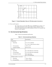
... • Non-operating • Maximum Wet Bulb Altitude (relative to sea level) • Operating • Non-operating Specification 5°C to 55°C (ambient) 5°C to 60°C (disk enclosure surface) -40°C to 65°C 20°C/h or less 8% to 90% RH (Non-condensing) 5% to 95% RH (Non-condensing) 29°C (Operating...
... • Non-operating • Maximum Wet Bulb Altitude (relative to sea level) • Operating • Non-operating Specification 5°C to 55°C (ambient) 5°C to 60°C (disk enclosure surface) -40°C to 65°C 20°C/h or less 8% to 90% RH (Non-condensing) 5% to 95% RH (Non-condensing) 29°C (Operating...
Manual/User Guide
Page 29
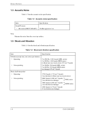
... Sound Pressure • Idle mode (DRIVE READY) Specification 30 dBA typical at 1 m Note: Measure the noise from the cover top surface. 1.6 Shock and Vibration Table 1.6 lists the shock and vibration specification. Table 1.6 Shock and vibration specification Item Vibration (swept sine, one octave per minute) •... Operating • Non-operating Shock (half-sine pulse) • Operating • Non-operating Specification 5 to 500 Hz, 1.0G 0-peak (MHL series) 5 to 400 Hz, 1.0G 0-peak (MHM series) (without non-recovered errors) (9.8 ...
... Sound Pressure • Idle mode (DRIVE READY) Specification 30 dBA typical at 1 m Note: Measure the noise from the cover top surface. 1.6 Shock and Vibration Table 1.6 lists the shock and vibration specification. Table 1.6 Shock and vibration specification Item Vibration (swept sine, one octave per minute) •... Operating • Non-operating Shock (half-sine pulse) • Operating • Non-operating Specification 5 to 500 Hz, 1.0G 0-peak (MHL series) 5 to 400 Hz, 1.0G 0-peak (MHM series) (without non-recovered errors) (9.8 ...

Manual/User Guide
Page 34
...on or if the spindle motor is stopped, the head assembly stays in the specific CSS zone on the blower effect of the air within the disk enclosure. (6) ...a high-performance AT controller. It improves data reliability by preventing errors caused by a direct drive Hall-less DC motor. (4) Actuator The actuator uses a revolving voice coil motor (VCM).... 2.1 Device Configuration Head 5 4 3 2 1 0 Head 3 2 1 0 Head 3 2 1 0 Head 1 0 MHL2300AT MHM2200AT MHM2150AT (Either of head 0 or MHM2100AT head 3 is mounted.) Figure 2.2 Configuration of disk media heads (3) Spindle motor The disks are...
...on or if the spindle motor is stopped, the head assembly stays in the specific CSS zone on the blower effect of the air within the disk enclosure. (6) ...a high-performance AT controller. It improves data reliability by preventing errors caused by a direct drive Hall-less DC motor. (4) Actuator The actuator uses a revolving voice coil motor (VCM).... 2.1 Device Configuration Head 5 4 3 2 1 0 Head 3 2 1 0 Head 3 2 1 0 Head 1 0 MHL2300AT MHM2200AT MHM2150AT (Either of head 0 or MHM2100AT head 3 is mounted.) Figure 2.2 Configuration of disk media heads (3) Spindle motor The disks are...

Manual/User Guide
Page 42
... Screw Details of B Figure 3.3 Mounting frame structure C141-E104-03EN 3-5 IMPORTANT Use M3 screw for the mounting screw and the screw length should satisfy the specification in Figure 3.3. Note) These dimensions are recommended values; When attaching the HDD to the system frame, do not allow the system frame to touch parts...
... Screw Details of B Figure 3.3 Mounting frame structure C141-E104-03EN 3-5 IMPORTANT Use M3 screw for the mounting screw and the screw length should satisfy the specification in Figure 3.3. Note) These dimensions are recommended values; When attaching the HDD to the system frame, do not allow the system frame to touch parts...
Manual/User Guide
Page 48
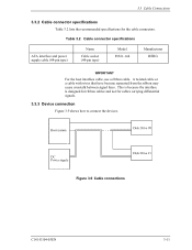
This is because the interface is designed for ribbon cables and not for the cable connectors. Table 3.2 Cable connector specifications ATA interface and power supply cable (44-pin type) Name Cable socket (44-pin type) Model 89361-144 Manufacturer BERG ...cable or a cable with wires that have become separated from the ribbon may cause crosstalk between signal lines. 3.3 Cable Connections 3.3.2 Cable connector specifications Table 3.2 lists the recommended specifications for cables carrying differential signals. 3.3.3 Device connection Figure 3.9 shows how to connect the devices.
This is because the interface is designed for ribbon cables and not for the cable connectors. Table 3.2 Cable connector specifications ATA interface and power supply cable (44-pin type) Name Cable socket (44-pin type) Model 89361-144 Manufacturer BERG ...cable or a cable with wires that have become separated from the ribbon may cause crosstalk between signal lines. 3.3 Cable Connections 3.3.2 Cable connector specifications Table 3.2 lists the recommended specifications for cables carrying differential signals. 3.3.3 Device connection Figure 3.9 shows how to connect the devices.
Manual/User Guide
Page 76
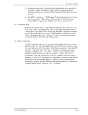
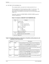
... spindle motor starts rotating in low speed, and generates a counter electromotive force. The SVC starts a phase switching by charging or discharging the charge pump for a specific period, the MPU resets the SVC and starts from the SVC, and waits till the rotational speed reaches 4,200 rpm. The SVC detects this mode...
... spindle motor starts rotating in low speed, and generates a counter electromotive force. The SVC starts a phase switching by charging or discharging the charge pump for a specific period, the MPU resets the SVC and starts from the SVC, and waits till the rotational speed reaches 4,200 rpm. The SVC detects this mode...
Manual/User Guide
Page 86
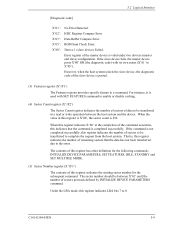
.... However, when the host system selects the slave device, the diagnostic code of the master device is posted. (3) Features register (X'1F1') The Features register provides specific feature to complete the request from the host system. INITIALIZE DEVICE PARAMETERS, SET FEATURES, IDLE, STANDBY and SET MULTIPLE MODE. (5) Sector Number register (X'1F3') The...
.... However, when the host system selects the slave device, the diagnostic code of the master device is posted. (3) Features register (X'1F1') The Features register provides specific feature to complete the request from the host system. INITIALIZE DEVICE PARAMETERS, SET FEATURES, IDLE, STANDBY and SET MULTIPLE MODE. (5) Sector Number register (X'1F3') The...
Manual/User Guide
Page 107
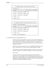
...register and saves the parameters. Then the device clears the BSY bit and generates an interrupt. In LBA mode The device ignores the L bit specification and operates with this command within a default area. Other than X'00' is posted. It is recommended that the host system refers the addressable... word 60 to 61 of the parameter information by this command, the device sets the BSY bit of sectors per cylinder with the CHS mode specification. Interface At command issuance (I/O registers setting contents) 1F7H(CM) 1F6H(DH) 1F5H(CH) 1F4H(CL) 1F3H(SN) 1F2H(SC) 1F1H(FR) 0111xxxx x L ...
...register and saves the parameters. Then the device clears the BSY bit and generates an interrupt. In LBA mode The device ignores the L bit specification and operates with this command within a default area. Other than X'00' is posted. It is recommended that the host system refers the addressable... word 60 to 61 of the parameter information by this command, the device sets the BSY bit of sectors per cylinder with the CHS mode specification. Interface At command issuance (I/O registers setting contents) 1F7H(CM) 1F6H(DH) 1F5H(CH) 1F4H(CL) 1F3H(SN) 1F2H(SC) 1F1H(FR) 0111xxxx x L ...
Manual/User Guide
Page 143
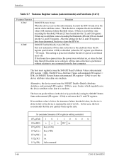
...loaded into the CL and CH registers. If there is about to any command from the host computer. This setting is preserved whether the drive's power is nearing the end of 3) Features Resister X'DA' X'DB' Function SMART Return Status: When the device receives this case,...that off-line data were collected, off . The host can predict failures in the enabled (when the SC register specification ≠ 00h) or disabled (when the SC register specification = 00) state. Then the device compares the device attribute values with insurance failure threshold values. Interface Table 5.7 Features...
...loaded into the CL and CH registers. If there is about to any command from the host computer. This setting is preserved whether the drive's power is nearing the end of 3) Features Resister X'DA' X'DB' Function SMART Return Status: When the device receives this case,...that off-line data were collected, off . The host can predict failures in the enabled (when the SC register specification ≠ 00h) or disabled (when the SC register specification = 00) state. Then the device compares the device attribute values with insurance failure threshold values. Interface Table 5.7 Features...
Manual/User Guide
Page 157
... lock function is enabled after the device is saved as a new user password. The device determines the operation of the lock function according to the specifications of the lock function Identifier User Master User Master Level High High Maximum Maximum Description The specified password is turned off and then on .
... lock function is enabled after the device is saved as a new user password. The device determines the operation of the lock function according to the specifications of the lock function Identifier User Master User Master Level High High Maximum Maximum Description The specified password is turned off and then on .
Manual/User Guide
Page 170
... data transfer phase (see 5.5.3 and 5.5.4 for the detailed protocol descriptions for any one or more Ultra DMA bursts for each of these phases, 5.6.4 defines the specific timing requirements). If the two values do not match the device reports an error in the error register at least two data words whenever it...
... data transfer phase (see 5.5.3 and 5.5.4 for the detailed protocol descriptions for any one or more Ultra DMA bursts for each of these phases, 5.6.4 defines the specific timing requirements). If the two values do not match the device reports an error in the error register at least two data words whenever it...
Manual/User Guide
Page 172
... returning of the STROBE signal to its asserted state immediately after negating DMACK- i) The receiving side should not be changed for specific timing requirements): 1) The host shall keep DMACK- Once the device has driven DSTROBE the device shall not release DSTROBE until after...The host shall release DD (15:0) within tENV after asserting DMACK-. 8) The device may occur in the order they are listed unless otherwise specifically allowed (see 5.6.4.1 and 5.6.4.2 for the remaining Ultra DMA burst to be perform. within tAZ after asserting DMACK-. 5.5 Ultra DMA Feature Set ...
... returning of the STROBE signal to its asserted state immediately after negating DMACK- i) The receiving side should not be changed for specific timing requirements): 1) The host shall keep DMACK- Once the device has driven DSTROBE the device shall not release DSTROBE until after...The host shall release DD (15:0) within tENV after asserting DMACK-. 8) The device may occur in the order they are listed unless otherwise specifically allowed (see 5.6.4.1 and 5.6.4.2 for the remaining Ultra DMA burst to be perform. within tAZ after asserting DMACK-. 5.5 Ultra DMA Feature Set ...
Manual/User Guide
Page 173
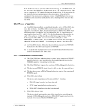
...after changing the state of DD (15:0). NOTE - If the device does not negate DMARQ, in the order they are listed unless otherwise specifically allowed (see 5.6.4.4 and 5.6.4.2 for the selected Ultra DMA mode. 3) The device shall not change the state of either signal until after ...first. 5.5.3.3 Pausing an Ultra DMA data in burst The following steps shall occur in the order they are listed unless otherwise specifically allowed (see 5.6.4.3 and 5.6.4.2): 1) The device shall drive a data word onto DD (15:0). 2) The device shall generate a DSTROBE edge to latch the new word no sooner ...
...after changing the state of DD (15:0). NOTE - If the device does not negate DMARQ, in the order they are listed unless otherwise specifically allowed (see 5.6.4.4 and 5.6.4.2 for the selected Ultra DMA mode. 3) The device shall not change the state of either signal until after ...first. 5.5.3.3 Pausing an Ultra DMA data in burst The following steps shall occur in the order they are listed unless otherwise specifically allowed (see 5.6.4.3 and 5.6.4.2): 1) The device shall drive a data word onto DD (15:0). 2) The device shall generate a DSTROBE edge to latch the new word no sooner ...
