Maintenance Manual
Page 16
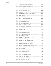
... (X '95' or X 'E1 5-47 (12) STANDBY (X '96' or X 'E2 5-49 (13) IDLE (X '97' or X 'E3 5-50 (14) CHECK POWER MODE (X '98' or X 'E5 5-52 (15) SLEEP (X '99' or X 'E6 5-53 (16) SMART (X 'B0 5-54 (17) DEVICE CONFIGURATION (X 'B1 5-84 (18) READ MULTIPLE (X 'C4 5-89 (19) WRITE MULTIPLE (X 'C5 5-92 (20) SET...
... (X '95' or X 'E1 5-47 (12) STANDBY (X '96' or X 'E2 5-49 (13) IDLE (X '97' or X 'E3 5-50 (14) CHECK POWER MODE (X '98' or X 'E5 5-52 (15) SLEEP (X '99' or X 'E6 5-53 (16) SMART (X 'B0 5-54 (17) DEVICE CONFIGURATION (X 'B1 5-84 (18) READ MULTIPLE (X 'C4 5-89 (19) WRITE MULTIPLE (X 'C5 5-92 (20) SET...

Maintenance Manual
Page 24
...at read). 1.1.2 Adaptability (1) Power save mode The disk drive is ideal for mobile use of certain Hazardous Substances in electrical and electronic equipment (RoHS) directive issued by APM function makes the disk drive ideal for applications since it supports the power save mode...greatly increases the positioning speed. And the disk drive realizes a high performance by each of the Idle, Standby, and Sleep modes and has the Partial and Slumber interface power management functions. The disk drive has a formatted capacity of 500GB (MJA2500BH), 400GB (MJA2400BH), 320GB (MJA2320BH), 250GB (...
...at read). 1.1.2 Adaptability (1) Power save mode The disk drive is ideal for mobile use of certain Hazardous Substances in electrical and electronic equipment (RoHS) directive issued by APM function makes the disk drive ideal for applications since it supports the power save mode...greatly increases the positioning speed. And the disk drive realizes a high performance by each of the Idle, Standby, and Sleep modes and has the Partial and Slumber interface power management functions. The disk drive has a formatted capacity of 500GB (MJA2500BH), 400GB (MJA2400BH), 320GB (MJA2320BH), 250GB (...
Maintenance Manual
Page 31
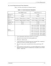
... (*5) 320 mA (1.5 Gbps)/340 mA (3.0 Gbps) 1.6 W (1.5 Gbps)/1.7 W (3.0 Gbps) Standby (*3) 26 mA 0.13 W Sleep (*3) 26 mA 0.13 W e rank (0.0012 W/GB): MJA2500BH e rank (0.0015 W/GB): MJA2400BH Energy Efficiency (*6) e rank (0.0019 W/GB): MJA2320BH ⎯ d rank (0.0024 W/GB): MJA2250BH d rank (0.0038 W/GB): MJA2160BH d rank (0.0050 W/GB): MJA2120BH d rank (0.0075 W/GB): MJA2080BH *1 Power requirements reflect typical values for +5 V power. *2 Maximum current and power at...
... (*5) 320 mA (1.5 Gbps)/340 mA (3.0 Gbps) 1.6 W (1.5 Gbps)/1.7 W (3.0 Gbps) Standby (*3) 26 mA 0.13 W Sleep (*3) 26 mA 0.13 W e rank (0.0012 W/GB): MJA2500BH e rank (0.0015 W/GB): MJA2400BH Energy Efficiency (*6) e rank (0.0019 W/GB): MJA2320BH ⎯ d rank (0.0024 W/GB): MJA2250BH d rank (0.0038 W/GB): MJA2160BH d rank (0.0050 W/GB): MJA2120BH d rank (0.0075 W/GB): MJA2080BH *1 Power requirements reflect typical values for +5 V power. *2 Maximum current and power at...

Maintenance Manual
Page 35
... in 107 seek operations. 1.9 Media Defects Defective sectors are executed. • STANDBY command issued • STANDBY IMMEDIATE command issued • SLEEP command issued • IDLE IMMEDIATE command (with unload feature) issued • Power Mode shifted with access to alternate sectors. 1.10 Load/...600,000 Load/Unload cycles. Read retries are automatically accessed by maximum read error Read errors that cannot be recovered by the disk drive. 1.8 Error Rate 1.8 Error Rate Known defects, for which alternative blocks can be recovered by one retry shall occur no more than...
... in 107 seek operations. 1.9 Media Defects Defective sectors are executed. • STANDBY command issued • STANDBY IMMEDIATE command issued • SLEEP command issued • IDLE IMMEDIATE command (with unload feature) issued • Power Mode shifted with access to alternate sectors. 1.10 Load/...600,000 Load/Unload cycles. Read retries are automatically accessed by maximum read error Read errors that cannot be recovered by the disk drive. 1.8 Error Rate 1.8 Error Rate Known defects, for which alternative blocks can be recovered by one retry shall occur no more than...
Maintenance Manual
Page 102
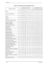
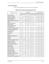
Interface Table 5.5 Command code and parameters (2/3) COMMAND NAME IDLE CHECK POWER MODE SLEEP SMART DEVICE CONFIGURATION READ MULTIPLE WRITE MULTIPLE SET MULTIPLE MODE READ DMA WRITE DMA READ BUFFER FLUSH CACHE WRITE BUFFER IDENTIFY DEVICE IDENTIFY DEVICE DMA ...
Interface Table 5.5 Command code and parameters (2/3) COMMAND NAME IDLE CHECK POWER MODE SLEEP SMART DEVICE CONFIGURATION READ MULTIPLE WRITE MULTIPLE SET MULTIPLE MODE READ DMA WRITE DMA READ BUFFER FLUSH CACHE WRITE BUFFER IDENTIFY DEVICE IDENTIFY DEVICE DMA ...

Maintenance Manual
Page 127
...or X 'E6') This command is to execute a software or COMRESET. • Error reporting conditions (1) A SATA communication error occurred (ST = 51h, ER = 14h). In the sleep mode, the spindle motor is stopped. At command issuance (Shadow Block Registers setting contents) CM X '99' or X 'E6' DH x x x x xx CH xx CL ... xx SC xx FR xx At command completion (Shadow Block Registers contents to the host system. Upon receipt of this command, the device enters the sleep mode, then reports the status to be read) ST Status information DH x x x x xx CH xx CL xx SN xx SC xx ER...
...or X 'E6') This command is to execute a software or COMRESET. • Error reporting conditions (1) A SATA communication error occurred (ST = 51h, ER = 14h). In the sleep mode, the spindle motor is stopped. At command issuance (Shadow Block Registers setting contents) CM X '99' or X 'E6' DH x x x x xx CH xx CL ... xx SC xx FR xx At command completion (Shadow Block Registers contents to the host system. Upon receipt of this command, the device enters the sleep mode, then reports the status to be read) ST Status information DH x x x x xx CH xx CL xx SN xx SC xx ER...
Maintenance Manual
Page 141
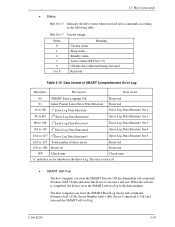
...; SMART Self-Test The host computer can read the SMART self-test log. 5.3 Host Commands • Status Bits 0 to 3: Indicates the drive status when received error commands according to the disk medium. The first sector is completed, the device saves the SMART self-test log to the... following table. Bits 4 to 7: Vendor unique Status 0 1 2 3 4 5 to F Meaning Unclear status Sleep status Standby status Active status (BSY bit = 0) Off-line data collection being executed Reserved Table 5.19 Data format of SMART Comprehensive Error Log Byte(hex...
...; SMART Self-Test The host computer can read the SMART self-test log. 5.3 Host Commands • Status Bits 0 to 3: Indicates the drive status when received error commands according to the disk medium. The first sector is completed, the device saves the SMART self-test log to the... following table. Bits 4 to 7: Vendor unique Status 0 1 2 3 4 5 to F Meaning Unclear status Sleep status Standby status Active status (BSY bit = 0) Off-line data collection being executed Reserved Table 5.19 Data format of SMART Comprehensive Error Log Byte(hex...

Maintenance Manual
Page 147
Drive State 00h = Active 01h = not support (Standby). 02h = not support (Sleep). 03h = DST executing in background 04h = SMART Off-line Data collection executing in background 05h = SCT command executing in background 06h-FFh = Reserved Reserved Extended ... Code Status of last SCT command issued * (See Table 5.25) Action Code Action code of last SCT command issued Function Code Function code of the drive is changed via SET MAX (EXT), DCO. 1= A WRITE SAME command to 0D 0E, 0F 10, 11 12, 13 Format Version SCT Version SCT Spec Status...
Drive State 00h = Active 01h = not support (Standby). 02h = not support (Sleep). 03h = DST executing in background 04h = SMART Off-line Data collection executing in background 05h = SCT command executing in background 06h-FFh = Reserved Reserved Extended ... Code Status of last SCT command issued * (See Table 5.25) Action Code Action code of last SCT command issued Function Code Function code of the drive is changed via SET MAX (EXT), DCO. 1= A WRITE SAME command to 0D 0E, 0F 10, 11 12, 13 Format Version SCT Version SCT Spec Status...
Maintenance Manual
Page 247
... SECTOR(S) WRITE VERIFY READ VERIFY SECTOR(S) SEEK EXECUTE DEVICE DIAGNOSTIC INITIALIZE DEVICE PARAMETERS DOWNLOAD MICROCODE STANDBY IMMEDIATE IDLE (UNLOAD) IMMEDIATE STANDBY IDLE CHECK POWER MODE SLEEP SMART DEVICE CONFIGURATION READ MULTIPLE WRITE MULTIPLE SET MULTIPLE MODE READ DMA WRITE DMA READ BUFFER FLUSH CACHE WRITE BUFFER IDENTIFY DEVICE IDENTIFY DEVICE DMA...
... SECTOR(S) WRITE VERIFY READ VERIFY SECTOR(S) SEEK EXECUTE DEVICE DIAGNOSTIC INITIALIZE DEVICE PARAMETERS DOWNLOAD MICROCODE STANDBY IMMEDIATE IDLE (UNLOAD) IMMEDIATE STANDBY IDLE CHECK POWER MODE SLEEP SMART DEVICE CONFIGURATION READ MULTIPLE WRITE MULTIPLE SET MULTIPLE MODE READ DMA WRITE DMA READ BUFFER FLUSH CACHE WRITE BUFFER IDENTIFY DEVICE IDENTIFY DEVICE DMA...

Maintenance Manual
Page 251
• SLEEP • DEVICE CONFIGRATION RESTORE • DEVICE CONFIGRATION FREEZE LOCK • WRITE UNCORRECTABLE EXT 5.4 Command Protocol The following is the protocol for command execution without data transfer: 1) The device receives a non-data command with the RegHD FIS. 2) The device executes the received command. 3) Command execution is completed. 4) The device reports the completion of command execution by sending to the host the RegDH FIS with 1 set in the I bit. Host RegHD RegDH Device Figure 5.13 Non-data command protocol C141-E293 5-177
• SLEEP • DEVICE CONFIGRATION RESTORE • DEVICE CONFIGRATION FREEZE LOCK • WRITE UNCORRECTABLE EXT 5.4 Command Protocol The following is the protocol for command execution without data transfer: 1) The device receives a non-data command with the RegHD FIS. 2) The device executes the received command. 3) Command execution is completed. 4) The device reports the completion of command execution by sending to the host the RegDH FIS with 1 set in the I bit. Host RegHD RegDH Device Figure 5.13 Non-data command protocol C141-E293 5-177
Maintenance Manual
Page 270
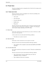
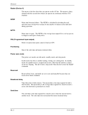
... mode. The heads are active. • Active mode • Active idle mode • Low power idle mode • Standby mode • Sleep mode The device enters the active idle mode by issuing a power command to the power save mode. The device enters the Active idle mode under...and Mode 2) • Upon completion of the power-on sequence is under the following conditions: • After completion of the command execution other than SLEEP and STANDBY commands. (3) Low power idle mode Sets circuits on the device are five types of power consumption state of the device including active mode...
... mode. The heads are active. • Active mode • Active idle mode • Low power idle mode • Standby mode • Sleep mode The device enters the active idle mode by issuing a power command to the power save mode. The device enters the Active idle mode under...and Mode 2) • Upon completion of the power-on sequence is under the following conditions: • After completion of the command execution other than SLEEP and STANDBY commands. (3) Low power idle mode Sets circuits on the device are five types of power consumption state of the device including active mode...

Maintenance Manual
Page 271
The drive enters the standby mode under the following commands is issued, the command is executed normally and the device is issued, response time to the command under the following condition: • A SLEEP command is ignored.) C141-E293 6-9 In this mode, the spindle motor has ...8226; STANDBY IMMEDIATE command • INITIALIZE DEVICE PARAMETERS command • CHECK POWER MODE command (5) Sleep mode Sleep mode is to the disk medium cannot be made immediately. The drive enters the sleep mode under the standby mode takes longer than the active, active idle, or low power idle ...
The drive enters the standby mode under the following commands is issued, the command is executed normally and the device is issued, response time to the command under the following condition: • A SLEEP command is ignored.) C141-E293 6-9 In this mode, the spindle motor has ...8226; STANDBY IMMEDIATE command • INITIALIZE DEVICE PARAMETERS command • CHECK POWER MODE command (5) Sleep mode Sleep mode is to the disk medium cannot be made immediately. The drive enters the sleep mode under the standby mode takes longer than the active, active idle, or low power idle ...
Maintenance Manual
Page 272
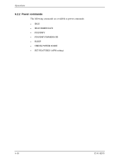
Operations 6.2.2 Power commands The following commands are available as power commands. • IDLE • IDLE IMMEDIATE • STANDBY • STANDBY IMMEDIATE • SLEEP • CHECK POWER MODE • SET FEATURES (APM setting) 6-10 C141-E293
Operations 6.2.2 Power commands The following commands are available as power commands. • IDLE • IDLE IMMEDIATE • STANDBY • STANDBY IMMEDIATE • SLEEP • CHECK POWER MODE • SET FEATURES (APM setting) 6-10 C141-E293
Maintenance Manual
Page 302
... the average time required for future standards. In idle mode, the drive is the average time required for half a disk rotation. The drive enters sleep mode when the host issues the SLEEP command. Rotational delay Time delay due to diagnose and repair a faulty drive. The mean rotational delay. The master is positioned on time) by...
... the average time required for future standards. In idle mode, the drive is the average time required for half a disk rotation. The drive enters sleep mode when the host issues the SLEEP command. Rotational delay Time delay due to diagnose and repair a faulty drive. The mean rotational delay. The master is positioned on time) by...

Maintenance Manual
Page 310
device to reference cylinder 4-17 orientation 3-3 out of band signaling 5-4 outer guard band 4-14 outerview, disk drive 2-2 outline 4-2 outline of interface 6-11 power supply configuration 4-4 power supply pin 3-10 IN-4 C141-E293 Index...microprocessor unit (MPU 4-13 miss-hit 6-16 mode active 6-8, 6-11 active idle 6-8 low power idle 6-8 partial 6-11 power save 6-8 settable 5-119 sleep 6-9 slumber 6-12 standby 6-9 model and product number 1-6 motor spindle 2-2 mounting 3-3 mounting frame structure 3-4 mounting limitation 3-4 N native queued command protocol.............
device to reference cylinder 4-17 orientation 3-3 out of band signaling 5-4 outer guard band 4-14 outerview, disk drive 2-2 outline 4-2 outline of interface 6-11 power supply configuration 4-4 power supply pin 3-10 IN-4 C141-E293 Index...microprocessor unit (MPU 4-13 miss-hit 6-16 mode active 6-8, 6-11 active idle 6-8 low power idle 6-8 partial 6-11 power save 6-8 settable 5-119 sleep 6-9 slumber 6-12 standby 6-9 model and product number 1-6 motor spindle 2-2 mounting 3-3 mounting frame structure 3-4 mounting limitation 3-4 N native queued command protocol.............
Maintenance Manual
Page 312
...13 shock and vibration 1-11 shock and vibration specification 1-11 signal interface regulation 5-4 signal segment 3-10 signal, interface 5-2 SLEEP 5-53 sleep mode 6-9 slope of an input voltage at rise 1-7 slumber mode 6-12 SMART 5-54 SMART command transport (SCT) ... 5-153, 5-163 software reset (SRST 5-26 software reset response 6-21 software reset, response to 6-7 software settings preservation 6-5 spare disk drive 7-15 specification 1-5 specification summary 1-5 spindle 4-2 spindle motor 2-2 spindle motor control 4-18 spindle motor control circuit 4-13 spindle motor driver ...
...13 shock and vibration 1-11 shock and vibration specification 1-11 signal interface regulation 5-4 signal segment 3-10 signal, interface 5-2 SLEEP 5-53 sleep mode 6-9 slope of an input voltage at rise 1-7 slumber mode 6-12 SMART 5-54 SMART command transport (SCT) ... 5-153, 5-163 software reset (SRST 5-26 software reset response 6-21 software reset, response to 6-7 software settings preservation 6-5 spare disk drive 7-15 specification 1-5 specification summary 1-5 spindle 4-2 spindle motor 2-2 spindle motor control 4-18 spindle motor control circuit 4-13 spindle motor driver ...