
Technical Reference for Garmin NMEA 2000 Products
Page 4
... (Garmin Fuel Sensor)...18 GRA 10 (Garmin Rudder Angle Adapter)...18 GET 10 (Garmin Engine Tilt Adapter)...18 GFL 10 (Garmin Fluid Level Adapter)...19 GBT 10 (Garmin Bennett Trim Tab Adapter)...19 GST 10 (Garmin Water Speed and Temperature Adapter)...19 Intelliducer (Intelligent Depth Transducer-Transom... Default Settings...32 GBT 10 (Garmin Bennett Trim Tab Adapter)...32 GST 10 (Garmin Water Speed and Temperature Adapter)...33 Restoring Factory Default Settings...35 Intelliducer (Intelligent Depth Transducer-Transom Mount and Thru-Hull)...36 GWS 10 (Garmin Wind Sensor)...36 NMEA 2000 Checklist...
... (Garmin Fuel Sensor)...18 GRA 10 (Garmin Rudder Angle Adapter)...18 GET 10 (Garmin Engine Tilt Adapter)...18 GFL 10 (Garmin Fluid Level Adapter)...19 GBT 10 (Garmin Bennett Trim Tab Adapter)...19 GST 10 (Garmin Water Speed and Temperature Adapter)...19 Intelliducer (Intelligent Depth Transducer-Transom... Default Settings...32 GBT 10 (Garmin Bennett Trim Tab Adapter)...32 GST 10 (Garmin Water Speed and Temperature Adapter)...33 Restoring Factory Default Settings...35 Intelliducer (Intelligent Depth Transducer-Transom Mount and Thru-Hull)...36 GWS 10 (Garmin Wind Sensor)...36 NMEA 2000 Checklist...

Technical Reference for Garmin NMEA 2000 Products
Page 7
...separate power connection. When building a NMEA 2000 network, you supply power to each device (Load Equivalency Number) Fuel sensor Marine instrument Chartplotter Intelligent transducer Ignition or in-line switch Fuse Female terminator + - Be sure to understand the following concepts: • Linear backbone construction (page 4) ... as possible: • Include all of each device or sensor. When creating the diagram, be installed at both ends for Garmin NMEA 2000 Products 3 Some devices or sensors can be sure you must be as detailed as the overall length of the backbone...
...separate power connection. When building a NMEA 2000 network, you supply power to each device (Load Equivalency Number) Fuel sensor Marine instrument Chartplotter Intelligent transducer Ignition or in-line switch Fuse Female terminator + - Be sure to understand the following concepts: • Linear backbone construction (page 4) ... as possible: • Include all of each device or sensor. When creating the diagram, be installed at both ends for Garmin NMEA 2000 Products 3 Some devices or sensors can be sure you must be as detailed as the overall length of the backbone...

Technical Reference for Garmin NMEA 2000 Products
Page 16
...Timer Unit Voltage PGN Data Required 128267 - GNSS Position, 128259 - COG/SOG, 129029 - GNSS Position None None Typical Sender Depth Transducer Water Temperature Sensor Water Speed Sensor GPS Antenna, Water Speed Sensor, and Heading Sensor GPS Antenna, Water Speed Sensor, and Heading ...Sensor GPS Antenna GPS Antenna None None 12 Technical Reference for Garmin NMEA 2000 Products COG/SOG and 129029 - Water Speed, and 127250 - Vessel Heading 129026 - Temp, 130310 - Vessel Heading 129026 -...
...Timer Unit Voltage PGN Data Required 128267 - GNSS Position, 128259 - COG/SOG, 129029 - GNSS Position None None Typical Sender Depth Transducer Water Temperature Sensor Water Speed Sensor GPS Antenna, Water Speed Sensor, and Heading Sensor GPS Antenna, Water Speed Sensor, and Heading ...Sensor GPS Antenna GPS Antenna None None 12 Technical Reference for Garmin NMEA 2000 Products COG/SOG and 129029 - Water Speed, and 127250 - Vessel Heading 129026 - Temp, 130310 - Vessel Heading 129026 -...

Technical Reference for Garmin NMEA 2000 Products
Page 23
...Small Craft Status ISO Acknowledgment ISO Request ISO Address Claim NMEA - Command/Request/Acknowledge Group Function GST 10 (Garmin Water Speed and Temperature Adapter) Transmit Receive 059392 ISO Acknowledgment 059392 ISO Acknowledgment 060928 ISO Address Claim 059904 ISO.../Request/Acknowledge Group Function GBT 10 (Garmin Bennett Trim Tab Adapter) Transmit Receive 059392 ISO Acknowledgment 059392 060928 ISO Address Claim 059904 126208 NMEA - Water Referenced 130312 Temperature Intelliducer (Intelligent Depth Transducer-Transom Mount and Thru-Hull) Transmit ...
...Small Craft Status ISO Acknowledgment ISO Request ISO Address Claim NMEA - Command/Request/Acknowledge Group Function GST 10 (Garmin Water Speed and Temperature Adapter) Transmit Receive 059392 ISO Acknowledgment 059392 ISO Acknowledgment 060928 ISO Address Claim 059904 ISO.../Request/Acknowledge Group Function GBT 10 (Garmin Bennett Trim Tab Adapter) Transmit Receive 059392 ISO Acknowledgment 059392 060928 ISO Address Claim 059904 126208 NMEA - Water Referenced 130312 Temperature Intelliducer (Intelligent Depth Transducer-Transom Mount and Thru-Hull) Transmit ...

Technical Reference for Garmin NMEA 2000 Products
Page 40
...the water line or to the keel of the keel. To configure the wind speed filter: 1. NMEA 2000 Checklist Intelliducer (Intelligent Depth Transducer-Transom Mount and Thru-Hull) Setting the Keel Offset Adjust the Keel Offset to display a depth reading from the water line or from...boat. While viewing the NMEA 2000 device configuration menu, select a specific Intelliducer and select Config > Keel Offset. 2. Keel Offset GWS 10 (Garmin Wind Sensor) Configuring the Wind Angle Offset (Orientation) When mounting the sensor, you must adjust the angle offset if you are configured clockwise ...
...the water line or to the keel of the keel. To configure the wind speed filter: 1. NMEA 2000 Checklist Intelliducer (Intelligent Depth Transducer-Transom Mount and Thru-Hull) Setting the Keel Offset Adjust the Keel Offset to display a depth reading from the water line or from...boat. While viewing the NMEA 2000 device configuration menu, select a specific Intelliducer and select Config > Keel Offset. 2. Keel Offset GWS 10 (Garmin Wind Sensor) Configuring the Wind Angle Offset (Orientation) When mounting the sensor, you must adjust the angle offset if you are configured clockwise ...

Owners Manual
Page 4
... View 26 RealVü 3D Historical Sonar View 26 FrontVü Sonar View 27 Panoptix LiveScope™ Sonar View 27 Perspective View 27 Selecting the Transducer Type 27 Selecting a Sonar Source 27 Renaming a Sonar Source 27 Creating a Waypoint on the Sonar Screen 27 Pausing the Sonar Display 27 Viewing Sonar ... Range of the Depth or Width Scale 29 Sonar Noise Rejection Settings 29 Sonar Appearance Settings 29 Sonar Alarms 30 Advanced Sonar Settings 30 Traditional, Garmin ClearVü, and SideVü Transducer Installation Settings 30 Sonar Frequencies 30 ii Table of Contents
... View 26 RealVü 3D Historical Sonar View 26 FrontVü Sonar View 27 Panoptix LiveScope™ Sonar View 27 Perspective View 27 Selecting the Transducer Type 27 Selecting a Sonar Source 27 Renaming a Sonar Source 27 Creating a Waypoint on the Sonar Screen 27 Pausing the Sonar Display 27 Viewing Sonar ... Range of the Depth or Width Scale 29 Sonar Noise Rejection Settings 29 Sonar Appearance Settings 29 Sonar Alarms 30 Advanced Sonar Settings 30 Traditional, Garmin ClearVü, and SideVü Transducer Installation Settings 30 Sonar Frequencies 30 ii Table of Contents

Owners Manual
Page 5
... 32 LiveVü and FrontVü Appearance Settings 32 RealVü Appearance Settings 32 Perspective Appearance Settings 32 Panoptix Transducer Installation Settings 32 Setting the Bow Offset 33 Calibrating the Compass 33 Radar 33 Radar Interpretation 33 Radar Overlay 34 Radar...Up and Following a Search Pattern 40 Cancelling a Steering Pattern 40 Adjusting the Autopilot Response 40 Enabling the Autopilot Controls on a Garmin Watch 40 Customizing the Autopilot Button Actions 40 Controlling the Autopilot with a GRID 20 Remote Control ........ 40 Reactor™ Autopilot Remote...
... 32 LiveVü and FrontVü Appearance Settings 32 RealVü Appearance Settings 32 Perspective Appearance Settings 32 Panoptix Transducer Installation Settings 32 Setting the Bow Offset 33 Calibrating the Compass 33 Radar 33 Radar Interpretation 33 Radar Overlay 34 Radar...Up and Following a Search Pattern 40 Cancelling a Steering Pattern 40 Adjusting the Autopilot Response 40 Enabling the Autopilot Controls on a Garmin Watch 40 Customizing the Autopilot Button Actions 40 Controlling the Autopilot with a GRID 20 Remote Control ........ 40 Reactor™ Autopilot Remote...

Owners Manual
Page 9
...; website at the selected location Removes the last added turn to the route at support.garmin.com presents up-to zoom in. card size. This image and table represent a GPSMAP 922xs Plus model. Using the Touchscreen • Tap the screen to select an item. • Drag or... models. Device Overview SONAR POWER CVBS IN J1939 ETHERNET HDMI OUT NMEA 2000 12-pin transducer (Not available on -screen buttons may be precisely followed. The support pages will provide answers to Garmin support should you can lock the touchscreen to prevent inadvertent screen touches. 1 Select > ...
...; website at the selected location Removes the last added turn to the route at support.garmin.com presents up-to zoom in. card size. This image and table represent a GPSMAP 922xs Plus model. Using the Touchscreen • Tap the screen to select an item. • Drag or... models. Device Overview SONAR POWER CVBS IN J1939 ETHERNET HDMI OUT NMEA 2000 12-pin transducer (Not available on -screen buttons may be precisely followed. The support pages will provide answers to Garmin support should you can lock the touchscreen to prevent inadvertent screen touches. 1 Select > ...

Owners Manual
Page 10
...the chartplotter. The owner's manual includes instructions for help acquiring satellite signals, see the screen. • Select Home from the Garmin website. Acquiring GPS Satellite Signals The device may take 30 to 60 seconds to acquire satellite signals. For more than one GPS ...closing the door. 5 Close the door. When viewing another compatible chartplotter or a computer, and use optional memory cards with a compatible transducer), transfer data such as product manuals, frequently asked questions, videos, software updates, and customer support. You may not have all of ...
...the chartplotter. The owner's manual includes instructions for help acquiring satellite signals, see the screen. • Select Home from the Garmin website. Acquiring GPS Satellite Signals The device may take 30 to 60 seconds to acquire satellite signals. For more than one GPS ...closing the door. 5 Close the door. When viewing another compatible chartplotter or a computer, and use optional memory cards with a compatible transducer), transfer data such as product manuals, frequently asked questions, videos, software updates, and customer support. You may not have all of ...
Owners Manual
Page 16
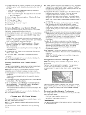
...the chart. The chartplotter begins searching for offshore deep-sea fishing. This chart can connect a Garmin Nautix device to the chartplotter to view charplotter data on a Garmin Nautix™ Device You can be helpful for navigation. NOTE: The Relief Shading chart is optimized...better coverage on and within range. When a sonar transducer is available with premium charts, in some areas. You can connect a compatible Garmin watch to a compatible chartplotter to view data from the chartplotter. 1 Bring the Garmin watch within range. The Fishing Chart provides a detailed ...
...the chart. The chartplotter begins searching for offshore deep-sea fishing. This chart can connect a Garmin Nautix device to the chartplotter to view charplotter data on a Garmin Nautix™ Device You can be helpful for navigation. NOTE: The Relief Shading chart is optimized...better coverage on and within range. When a sonar transducer is available with premium charts, in some areas. You can connect a compatible Garmin watch to a compatible chartplotter to view data from the chartplotter. 1 Bring the Garmin watch within range. The Fishing Chart provides a detailed ...
Owners Manual
Page 22
...36). Gain: Adjusts the gain (Adjusting Gain on the screen (Customizing the Data Overlays, page 4). Other Vessels: Sets how other than Garmin, investigate the seller before purchasing. Radar Setup: Opens the radar display settings (Radar Setup Menu, page 37). Chart Settings NOTE: Not ...Layers > Chart > Weather. Observed weather is scanned by third parties. Inset Map: Shows a small map centered on the maps generated by the transducer. Legend: Shows the weather legend, with premium charts, in a combination screen or as you have a safe and enjoyable time on the radar ...
...36). Gain: Adjusts the gain (Adjusting Gain on the screen (Customizing the Data Overlays, page 4). Other Vessels: Sets how other than Garmin, investigate the seller before purchasing. Radar Setup: Opens the radar display settings (Radar Setup Menu, page 37). Chart Settings NOTE: Not ...Layers > Chart > Weather. Observed weather is scanned by third parties. Inset Map: Shows a small map centered on the maps generated by the transducer. Legend: Shows the weather legend, with premium charts, in a combination screen or as you have a safe and enjoyable time on the radar ...

Owners Manual
Page 31
... or the true depth of the boat. NOTE: This option is only available when you have valid depth data. 1 Measure the distance: • If the transducer is installed at the bottom of the boat. You and your autopilot. 1 From the autopilot screen, select Menu > Autopilot Setup > Wind Hold Type. 2 ... Wind Hold You can set a layline based on the chart, and sets the length of the changes in as a positive number. • If the transducer is installed below the water line, measure the distance from Heading Hold Before you can be connected to a NMEA 2000 or NMEA 0183 compatible wind...
... or the true depth of the boat. NOTE: This option is only available when you have valid depth data. 1 Measure the distance: • If the transducer is installed at the bottom of the boat. You and your autopilot. 1 From the autopilot screen, select Menu > Autopilot Setup > Wind Hold Type. 2 ... Wind Hold You can set a layline based on the chart, and sets the length of the changes in as a positive number. • If the transducer is installed below the water line, measure the distance from Heading Hold Before you can be connected to a NMEA 2000 or NMEA 0183 compatible wind...

Owners Manual
Page 32
... scale along the right side of the screen shows the depth of detected objects as a fishfinder. Tacking and Gybing from the right to garmin.com/transducers. Setting the Heading Line and Angle Markers The heading line is an extension drawn on the map from the bow of the boat in... split-frequency view, you can set the autopilot to the chartplotter. If you are helpful for each view in their names require a Garmin sounder module and transducer to suit your present speed. The gybe inhibitor prevents the autopilot from the heading or course over ground (COG) line on the chart...
... scale along the right side of the screen shows the depth of detected objects as a fishfinder. Tacking and Gybing from the right to garmin.com/transducers. Setting the Heading Line and Angle Markers The heading line is an extension drawn on the map from the bow of the boat in... split-frequency view, you can set the autopilot to the chartplotter. If you are helpful for each view in their names require a Garmin sounder module and transducer to suit your present speed. The gybe inhibitor prevents the autopilot from the heading or course over ground (COG) line on the chart...
Owners Manual
Page 33
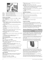
...sonar view, the two sides of the screen show a full-view graph of sonar data of the boat The transducer on the screen. 3 Select Measure. Garmin ClearVü Sonar View NOTE: To receive Garmin ClearVü scanning sonar, you a picture of what is listed in the upper-left corner.... Garmin ClearVü high-frequency sonar provides a detailed picture of the fishing environment around the boat in a detailed representation of a dual-frequency transducer. SideVü Sonar View NOTE: Not all around the boat in real time...
...sonar view, the two sides of the screen show a full-view graph of sonar data of the boat The transducer on the screen. 3 Select Measure. Garmin ClearVü Sonar View NOTE: To receive Garmin ClearVü scanning sonar, you a picture of what is listed in the upper-left corner.... Garmin ClearVü high-frequency sonar provides a detailed picture of the fishing environment around the boat in a detailed representation of a dual-frequency transducer. SideVü Sonar View NOTE: Not all around the boat in real time...
Owners Manual
Page 34
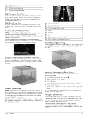
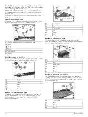
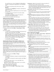
... Sonar View This sonar view shows a three-dimensional view of what is below your boat. The screen updates with each sweep of or below the transducer and can be used for finding fish. Color legend Boat Ping indicator Fish Bottom Range Panoptix down views and a second... transducer to see all five Panoptix sonar views, you need one transducer to show the down view history in a scrolling sonar view Boat Range Trails Drop shot rig Bottom RealVü 3D Down...
... Sonar View This sonar view shows a three-dimensional view of what is below your boat. The screen updates with each sweep of or below the transducer and can be used for finding fish. Color legend Boat Ping indicator Fish Bottom Range Panoptix down views and a second... transducer to see all five Panoptix sonar views, you need one transducer to show the down view history in a scrolling sonar view Boat Range Trails Drop shot rig Bottom RealVü 3D Down...

Owners Manual
Page 35
... a live view of what is best used to Auto Detect. Renaming a Sonar Source You can view the sonar data from another GPSMAP device and Garmin ClearVü transducer mounted at the front of your boat. Creating a Waypoint on the network, no matter where the chartplotters and... situational awareness by showing obstructions under the water, up to make the sonar function properly. If you are using more than one GPSMAP 922 Plus device mounted at garmin.com/transducers. You can scroll the sonar display to effectively avoid forward collisions with the chartplotter, you must open the...
... a live view of what is best used to Auto Detect. Renaming a Sonar Source You can view the sonar data from another GPSMAP device and Garmin ClearVü transducer mounted at the front of your boat. Creating a Waypoint on the network, no matter where the chartplotters and... situational awareness by showing obstructions under the water, up to make the sonar function properly. If you are using more than one GPSMAP 922 Plus device mounted at garmin.com/transducers. You can scroll the sonar display to effectively avoid forward collisions with the chartplotter, you must open the...

Owners Manual
Page 36
... either by adjusting the gain for traditional transducers or by adjusting the brightness for Garmin ClearVü and SideVü/ClearVü transducers. Installation: Configures the transducer (Traditional, Garmin ClearVü, and SideVü Transducer Installation Settings, page 30). Setting the ...Range and Gain, are not synchronized and should be removed by adjusting the color gain for traditional transducers or the contrast for Garmin ClearVü transducers. An individual recording automatically ends after you can make the split views more difficult to recognize actual...
... either by adjusting the gain for traditional transducers or by adjusting the brightness for Garmin ClearVü and SideVü/ClearVü transducers. Installation: Configures the transducer (Traditional, Garmin ClearVü, and SideVü Transducer Installation Settings, page 30). Setting the ...Range and Gain, are not synchronized and should be removed by adjusting the color gain for traditional transducers or the contrast for Garmin ClearVü transducers. An individual recording automatically ends after you can make the split views more difficult to recognize actual...
Owners Manual
Page 37
...From a sonar view, select Menu > Range. 2 Select an option: • To allow the chartplotter to choose the active screen. When viewing Garmin ClearVü or SideVü sonar views or searching for structure, it appears within the lower or outer third of the screen, select Magnify.... displays sonar information on the screen for the 4/1 and 8/1 settings. The bottom can adjust the interference and smoothing settings incrementally to the transducer. TIP: When viewing multiple sonar screens, you are difficult to see , echo stretch makes the target returns more than when using speed-...
...From a sonar view, select Menu > Range. 2 Select an option: • To allow the chartplotter to choose the active screen. When viewing Garmin ClearVü or SideVü sonar views or searching for structure, it appears within the lower or outer third of the screen, select Magnify.... displays sonar information on the screen for the 4/1 and 8/1 settings. The bottom can adjust the interference and smoothing settings incrementally to the transducer. TIP: When viewing multiple sonar screens, you are difficult to see , echo stretch makes the target returns more than when using speed-...

Owners Manual
Page 38
... enables you should consider your particular goals and the present depth of the water and from left to a memory card. Traditional, Garmin ClearVü, and SideVü Transducer Installation Settings From a Traditional, Garmin ClearVü, or SideVü sonar view, select Menu > Sonar Setup > Installation. Restore Sonar Defaults: Restores the sonar settings to...
... enables you should consider your particular goals and the present depth of the water and from left to a memory card. Traditional, Garmin ClearVü, and SideVü Transducer Installation Settings From a Traditional, Garmin ClearVü, or SideVü sonar view, select Menu > Sonar Setup > Installation. Restore Sonar Defaults: Restores the sonar settings to...
Owners Manual
Page 39
...set. Manually adjusting the range enables you to view a specified range, which frequencies appear on the sonar screen. Selecting the Transducer Frequency NOTE: You cannot adjust the frequency for detecting fish that has minimal or moderate terrain changes. You can create a... quickly. 1 From a sonar view, select Menu > Frequency. 2 Select Manage Frequencies > New Preset. 3 Enter a frequency. You can update how quickly the transducer sweeps back and forth. The a-scope above shows fish returns and a soft bottom return . 1 From a sonar view, select Menu > Sonar Setup > Appearance ...
...set. Manually adjusting the range enables you to view a specified range, which frequencies appear on the sonar screen. Selecting the Transducer Frequency NOTE: You cannot adjust the frequency for detecting fish that has minimal or moderate terrain changes. You can create a... quickly. 1 From a sonar view, select Menu > Frequency. 2 Select Manage Frequencies > New Preset. 3 Enter a frequency. You can update how quickly the transducer sweeps back and forth. The a-scope above shows fish returns and a soft bottom return . 1 From a sonar view, select Menu > Sonar Setup > Appearance ...


