

8512055 - Component Replacement Manual
Page 3
...a safe place. Warning To avoid exposure to dangerous electrical voltages and moving parts, turn off your notebook. 4 Disconnect the AC adapter, modem cable, and network cable. 5 Disconnect all peripheral devices and remove any PC Cards. 6 Turn your notebook over any ...keyboard screw hole is marked with notebook components, follow these screws cannot be removed), then remove the memory bay cover. Screw 8 Loosen the six memory bay cover screws (these guidelines: • Avoid static-causing surfaces such as electrostatic discharge (ESD). www.gateway.com © 2007 Gateway, Inc. Gateway...
...a safe place. Warning To avoid exposure to dangerous electrical voltages and moving parts, turn off your notebook. 4 Disconnect the AC adapter, modem cable, and network cable. 5 Disconnect all peripheral devices and remove any PC Cards. 6 Turn your notebook over any ...keyboard screw hole is marked with notebook components, follow these screws cannot be removed), then remove the memory bay cover. Screw 8 Loosen the six memory bay cover screws (these guidelines: • Avoid static-causing surfaces such as electrostatic discharge (ESD). www.gateway.com © 2007 Gateway, Inc. Gateway...

8512055 - Component Replacement Manual
Page 4
... in Step 9. 13 Replace the memory bay cover, then tighten the six cover screws. 14 Replace the keyboard screw. 15 Insert the battery, then turn your notebook over. 16 Connect the power adapter, modem cable, and network cable, then turn on the DVD bracket. DVD bracket Replacing the DVD Drive 11...Support See the label on the bottom of the drive bay by pushing on your Reference Guide for Customer Care Information. Gateway and eMachines are trademarks or registered trademarks of Gateway, Inc. Make sure that the drive fits securely in the bay. 12 Secure the DVD drive with the screw ...
... in Step 9. 13 Replace the memory bay cover, then tighten the six cover screws. 14 Replace the keyboard screw. 15 Insert the battery, then turn your notebook over. 16 Connect the power adapter, modem cable, and network cable, then turn on the DVD bracket. DVD bracket Replacing the DVD Drive 11...Support See the label on the bottom of the drive bay by pushing on your Reference Guide for Customer Care Information. Gateway and eMachines are trademarks or registered trademarks of Gateway, Inc. Make sure that the drive fits securely in the bay. 12 Secure the DVD drive with the screw ...

8512055 - Component Replacement Manual
Page 6
...installed software and device drivers. 20 Reconnect all peripheral devices and replace any key on your keyboard. A list of the notebook for important safety, regulatory, and legal information. 2 www.gateway.com © 2007 Gateway, Inc. Replacing the Hard Drive Kit 10 Place the new drive, label side up, ...screws. 13 Insert the battery and turn your notebook over. 14 Connect the power adapter, modem cable, and network cable. 15 Turn on your notebook. 16 If the hard drive was sent to you from Gateway with the operating system, applications, and drivers installed, you created to Step 20...
...installed software and device drivers. 20 Reconnect all peripheral devices and replace any key on your keyboard. A list of the notebook for important safety, regulatory, and legal information. 2 www.gateway.com © 2007 Gateway, Inc. Replacing the Hard Drive Kit 10 Place the new drive, label side up, ...screws. 13 Insert the battery and turn your notebook over. 14 Connect the power adapter, modem cable, and network cable. 15 Turn on your notebook. 16 If the hard drive was sent to you from Gateway with the operating system, applications, and drivers installed, you created to Step 20...

8512055 - Component Replacement Manual
Page 7
...a bare metal surface on your notebook are extremely sensitive to replace the keyboard. For more information, see "Changing Batteries" in your notebook. Screw Screw 9 Turn your notebook and unplug the AC adapter, modem cable, and network cable before replacing a component. Screw Screw... inside of their edges. All rights reserved. Do not lay components on the bottom of Gateway, Inc. Replacing the Keyboard 6 With a small Phillips screwdriver, remove the keyboard screw and put them . ESD can permanently damage electrostatic discharge-sensitive components in your notebook ...
...a bare metal surface on your notebook are extremely sensitive to replace the keyboard. For more information, see "Changing Batteries" in your notebook. Screw Screw 9 Turn your notebook and unplug the AC adapter, modem cable, and network cable before replacing a component. Screw Screw... inside of their edges. All rights reserved. Do not lay components on the bottom of Gateway, Inc. Replacing the Keyboard 6 With a small Phillips screwdriver, remove the keyboard screw and put them . ESD can permanently damage electrostatic discharge-sensitive components in your notebook ...

8512055 - Component Replacement Manual
Page 8
... the LCD panel, then replace the two hinge cover screws. 8 Turn your notebook over . 13 Connect the power adapter, the modem cable, and the network cable, then turn on top of the keyboard into their respective companies. 13 Insert the small flat-blade screwdriver under the palm rest. Replacing the...See your notebook with the space bar away from you finger along the front edge of Gateway, Inc. All rights reserved. All other brands and product names are trademarks or registered trademarks of the keyboard to lock the connector in several places until it up . 4 Insert the tabs on ...
... the LCD panel, then replace the two hinge cover screws. 8 Turn your notebook over . 13 Connect the power adapter, the modem cable, and the network cable, then turn on top of the keyboard into their respective companies. 13 Insert the small flat-blade screwdriver under the palm rest. Replacing the...See your notebook with the space bar away from you finger along the front edge of Gateway, Inc. All rights reserved. All other brands and product names are trademarks or registered trademarks of the keyboard to lock the connector in several places until it up . 4 Insert the tabs on ...

8512055 - Component Replacement Manual
Page 9
... 6 With a small Phillips screwdriver, remove the keyboard screw and put it to replace the memory module. Tips & Tricks The keyboard screw hole is facing up, then remove the ...bay cover. Screw Preventing static electricity discharge The components inside of Gateway, Inc. Gateway and eMachines are trademarks or registered trademarks of the bags provide electrostatic protection. ... under "Preventing static electricity discharge." 2 Turn off your notebook and unplug the AC adapter, modem cable, and network cable before replacing a component. Technical Support See the label...
... 6 With a small Phillips screwdriver, remove the keyboard screw and put it to replace the memory module. Tips & Tricks The keyboard screw hole is facing up, then remove the ...bay cover. Screw Preventing static electricity discharge The components inside of Gateway, Inc. Gateway and eMachines are trademarks or registered trademarks of the bags provide electrostatic protection. ... under "Preventing static electricity discharge." 2 Turn off your notebook and unplug the AC adapter, modem cable, and network cable before replacing a component. Technical Support See the label...

8512055 - Component Replacement Manual
Page 10
...angle and insert it clicks in the United States and other brands and product names are trademarks or registered trademarks of Gateway, Inc. Gateway and eMachines are trademarks or registered trademarks of their respective companies. All rights reserved. Technical Support See the label on.... 2 www.gateway.com © 2007 Gateway, Inc. See your notebook. in place. 12 Replace the memory bay cover, then tighten the six cover screws. 13 Replace the keyboard screw. 14 Insert the battery, then turn your notebook over. 15 Connect the power adapter, the modem cable...
...angle and insert it clicks in the United States and other brands and product names are trademarks or registered trademarks of Gateway, Inc. Gateway and eMachines are trademarks or registered trademarks of their respective companies. All rights reserved. Technical Support See the label on.... 2 www.gateway.com © 2007 Gateway, Inc. See your notebook. in place. 12 Replace the memory bay cover, then tighten the six cover screws. 13 Replace the keyboard screw. 14 Insert the battery, then turn your notebook over. 15 Connect the power adapter, the modem cable...
8512488 - Gateway Notebook Reference Guide R2
Page 3
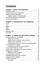
...Accessing your online User Guide 2 Gateway contact information 2 Gateway model and serial number 3 Microsoft Certificate of Authenticity 3 For more information 3 Chapter 2: Checking Out Your Notebook . . . . . 5 Front 6 Left 7 Right 8 Back 9 Bottom 10 Keyboard area 11 LCD panel 12 Chapter... 3: Setting Up and Getting Started . . 13 Working safely and comfortably 14 Reducing eye strain 14 Setting up your computer desk and chair 15 Sitting at your notebook 15 Avoiding discomfort and injury from repetitive strain . . 15 Connecting the AC adapter...
...Accessing your online User Guide 2 Gateway contact information 2 Gateway model and serial number 3 Microsoft Certificate of Authenticity 3 For more information 3 Chapter 2: Checking Out Your Notebook . . . . . 5 Front 6 Left 7 Right 8 Back 9 Bottom 10 Keyboard area 11 LCD panel 12 Chapter... 3: Setting Up and Getting Started . . 13 Working safely and comfortably 14 Reducing eye strain 14 Setting up your computer desk and chair 15 Sitting at your notebook 15 Avoiding discomfort and injury from repetitive strain . . 15 Connecting the AC adapter...

8512488 - Gateway Notebook Reference Guide R2
Page 19
CHAPTER3 Setting Up and Getting Started • Working safely and comfortably • Connecting the AC adapter • Connecting the dial-up modem • Connecting to a broadband modem or network • Starting your notebook • Turning off your notebook • Restarting (rebooting) your notebook • Using the status indicators • Using the keyboard • Using the EZ Pad touchpad • Using the optional multimedia panel • Using the optional webcam • Adjusting the brightness • Adjusting the volume • Turning your wireless radio on or off 13
CHAPTER3 Setting Up and Getting Started • Working safely and comfortably • Connecting the AC adapter • Connecting the dial-up modem • Connecting to a broadband modem or network • Starting your notebook • Turning off your notebook • Restarting (rebooting) your notebook • Using the status indicators • Using the keyboard • Using the EZ Pad touchpad • Using the optional multimedia panel • Using the optional webcam • Adjusting the brightness • Adjusting the volume • Turning your wireless radio on or off 13

8512488 - Gateway Notebook Reference Guide R2
Page 105
www.gateway.com 10 Pull the memory module out of the slot. 11 Hold the new or replacement module at a 30-degree angle and press it can only be inserted in the memory bay. 12 Replace the memory bay cover, then tighten the cover screws. 13 Replace the keyboard screw. This module is... fit, make sure that the notch in the module lines up with a K. 14 Insert the battery, then turn your notebook over. 15 Connect the power adapter, modem cable, and network cable. 16 Reconnect all peripheral devices and replace any PC Cards or Express Cards. 99
www.gateway.com 10 Pull the memory module out of the slot. 11 Hold the new or replacement module at a 30-degree angle and press it can only be inserted in the memory bay. 12 Replace the memory bay cover, then tighten the cover screws. 13 Replace the keyboard screw. This module is... fit, make sure that the notch in the module lines up with a K. 14 Insert the battery, then turn your notebook over. 15 Connect the power adapter, modem cable, and network cable. 16 Reconnect all peripheral devices and replace any PC Cards or Express Cards. 99

8512488 - Gateway Notebook Reference Guide R2
Page 108
... new hard drive kit into your notebook, then replace the cover screws. 16 Insert the battery, then turn your notebook over. 17 Connect the power adapter, modem cable, and network cable. 18 Turn on your notebook, open the DVD drive, insert the Windows DVD, close the DVD drive, then restart your... drive label side up onto the cover so the screw holes line up. 14 Replace the screws that secure the hard drive to insert your keyboard and follow the on your Drivers and Applications Recovery disc. 20 Reconnect all peripheral devices and replace any key on -screen instructions.
... new hard drive kit into your notebook, then replace the cover screws. 16 Insert the battery, then turn your notebook over. 17 Connect the power adapter, modem cable, and network cable. 18 Turn on your notebook, open the DVD drive, insert the Windows DVD, close the DVD drive, then restart your... drive label side up onto the cover so the screw holes line up. 14 Replace the screws that secure the hard drive to insert your keyboard and follow the on your Drivers and Applications Recovery disc. 20 Reconnect all peripheral devices and replace any key on -screen instructions.

8512488 - Gateway Notebook Reference Guide R2
Page 148
... LCD panel 77 notebook exterior 76 screen 77 clicking 30 closing unresponsive program 22 connecting AC adapter 16 cable modem 19 dial-up modem 18 DSL modem 19 external keyboard 24 external monitor 50 keyboard 24 mouse 29 printer 48 projector 50 scanner 48 television 54 to wired Ethernet 19 USB device 48... camera 8, 48 DSL modem 8, 19 Ethernet 8 external audio 6 external diskette drive 8, 48 external speakers 6 Firewire 8, 48 flash drive 8, 48 headphone 6 i.Link 8, 48 IEEE 1394 8, 48 keyboard 8 microphone 6 modem (dial-up) 8 monitor (VGA) 9, 51 mouse 8
... LCD panel 77 notebook exterior 76 screen 77 clicking 30 closing unresponsive program 22 connecting AC adapter 16 cable modem 19 dial-up modem 18 DSL modem 19 external keyboard 24 external monitor 50 keyboard 24 mouse 29 printer 48 projector 50 scanner 48 television 54 to wired Ethernet 19 USB device 48... camera 8, 48 DSL modem 8, 19 Ethernet 8 external audio 6 external diskette drive 8, 48 external speakers 6 Firewire 8, 48 flash drive 8, 48 headphone 6 i.Link 8, 48 IEEE 1394 8, 48 keyboard 8 microphone 6 modem (dial-up) 8 monitor (VGA) 9, 51 mouse 8

8512488 - Gateway Notebook Reference Guide R2
Page 151
www.gateway.com K Kensington cable lock 72 lock slot 7 key combinations 26 keyboard buttons 24 cleaning 77 connecting 24 features 24 keys 24 locating 11 troubleshooting 112 USB port 8 keys application 25 arrow 25 brightness 27 directional 25 ... microphone built-in 11 jack 6 Microsoft Certificate of Authenticity 3 model number 3, 72 modem cable 8, 19 connecting 18, 19 dial-up 18, 70 DSL 8, 19 international adapter 70 jack (dial-up) 8, 18 troubleshooting 116 145
www.gateway.com K Kensington cable lock 72 lock slot 7 key combinations 26 keyboard buttons 24 cleaning 77 connecting 24 features 24 keys 24 locating 11 troubleshooting 112 USB port 8 keys application 25 arrow 25 brightness 27 directional 25 ... microphone built-in 11 jack 6 Microsoft Certificate of Authenticity 3 model number 3, 72 modem cable 8, 19 connecting 18, 19 dial-up 18, 70 DSL 8, 19 international adapter 70 jack (dial-up) 8, 18 troubleshooting 116 145


