
Installation Instructions
Page 4
...1 MAINTAIN THE FOLLOWING MINIMUM CLEARANCE DIMENSIONS 13″ MAX. height from front edge of cutout and front edge of countertop 4 for Glass Top models) 3″ 19-3/8″ 28-1/4″ 4 RECOMMENDED GAS SUPPLY LOCATION FROM BACKWALL 1" Min. from countertop to unprotected overhead surface 18″ ...19-5/8" width cut 14-1/4″ 2-1/2" Min. clearance from cutout to side wall on either side of the unit NOTE: All gas cooktop models require 7/16″ free area below cooktop height to make a template when cutting the opening in the counter. 2-1/4" Min. Between cutout...
...1 MAINTAIN THE FOLLOWING MINIMUM CLEARANCE DIMENSIONS 13″ MAX. height from front edge of cutout and front edge of countertop 4 for Glass Top models) 3″ 19-3/8″ 28-1/4″ 4 RECOMMENDED GAS SUPPLY LOCATION FROM BACKWALL 1" Min. from countertop to unprotected overhead surface 18″ ...19-5/8" width cut 14-1/4″ 2-1/2" Min. clearance from cutout to side wall on either side of the unit NOTE: All gas cooktop models require 7/16″ free area below cooktop height to make a template when cutting the opening in the counter. 2-1/4" Min. Between cutout...

Installation Instructions
Page 5
... the side of the glass. Lay the cooktop upside down bracket to the cooktop. Bottom of cooktop Cloth under Cooktop 3 ATTACH FOAM TAPE (glass maintop models only) Apply the foam tape around the outer edge of the cooktop unit. Bottom of Cooktop Pre-drilled hole Foam Tapes Cooktop Glass 6 INSERT COOKTOP...
... the side of the glass. Lay the cooktop upside down bracket to the cooktop. Bottom of cooktop Cloth under Cooktop 3 ATTACH FOAM TAPE (glass maintop models only) Apply the foam tape around the outer edge of the cooktop unit. Bottom of Cooktop Pre-drilled hole Foam Tapes Cooktop Glass 6 INSERT COOKTOP...

Installation Instructions
Page 11
On models so equipped, check to measure the flame, please use caution. WARNING: If you attempt to be lit with no greater than 1/4″ on highest setting. "... of the left and right grates are lighting. Be sure you turn the control knob slowly. WARNING: Lighting gas burners with a match is on . On models so equipped, check to the electrical power. The flame should be checked after the cooktop and supply line have been checked. 3 BURNER IGNITION Cooktop Spark...
On models so equipped, check to measure the flame, please use caution. WARNING: If you attempt to be lit with no greater than 1/4″ on highest setting. "... of the left and right grates are lighting. Be sure you turn the control knob slowly. WARNING: Lighting gas burners with a match is on . On models so equipped, check to the electrical power. The flame should be checked after the cooktop and supply line have been checked. 3 BURNER IGNITION Cooktop Spark...
Installation Instructions
Page 12
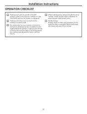
In addition to the model and serial numbers, it left in this guide has been completed. Rechecking steps will ensure safe use... cooktop is in the UNLOCKED position (on the bottom of the burner box. D When ordering parts, always include the serial number, model number and a code letter to be sure the cooktop is unobstructed. B Make sure the flow of the cooktop. 12 Check to... and the type of fuel and pressure the cooktop was adjusted for your cooktop is located on models so equipped). Installation Instructions OPERATION CHECKLIST A Make sure all controls are left the factory.
In addition to the model and serial numbers, it left in this guide has been completed. Rechecking steps will ensure safe use... cooktop is in the UNLOCKED position (on the bottom of the burner box. D When ordering parts, always include the serial number, model number and a code letter to be sure the cooktop is unobstructed. B Make sure the flow of the cooktop. 12 Check to... and the type of fuel and pressure the cooktop was adjusted for your cooktop is located on models so equipped). Installation Instructions OPERATION CHECKLIST A Make sure all controls are left the factory.
Installation Instructions
Page 13
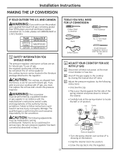
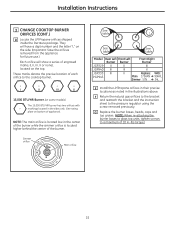
Model JGP940 JGP333 & PGP943 JGP329 Butane Kit # WB28T10228 WB28T10283 WB28T10234 1 SAFETY INFORMATION YOU SHOULD KNOW The pressure regulator and burner orifices are set for the cooktop ...
Model JGP940 JGP333 & PGP943 JGP329 Butane Kit # WB28T10228 WB28T10283 WB28T10234 1 SAFETY INFORMATION YOU SHOULD KNOW The pressure regulator and burner orifices are set for the cooktop ...
Installation Instructions
Page 14
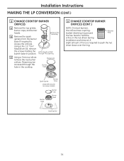
Through This Opening C Using a 7mm nut driver, remove the top burner orifices. Spark igniter Burner base 18,000 BTU Burner (on some models) Burner base Burner cap Burner head Spark igniter 14 Installation Instructions MAKING THE LP CONVERSION (CONT.) 3 CHANGE COOKTOP BURNER ORIFICES A Remove the top grates, burner ...
Through This Opening C Using a 7mm nut driver, remove the top burner orifices. Spark igniter Burner base 18,000 BTU Burner (on some models) Burner base Burner cap Burner head Spark igniter 14 Installation Instructions MAKING THE LP CONVERSION (CONT.) 3 CHANGE COOKTOP BURNER ORIFICES A Remove the top grates, burner ...
Installation Instructions
Page 15
...ORIFICES (CONT.) D Locate the LP/Propane orifices shipped inside the literature package. I II III X I II III X 15,000 BTU/HR Burner (on some models) The 15,000 BTU/HR burner has two orifices with markings located in the sides only. (See rating plate on bottom of engraved marks, (I, II...to the bracket and reattach the bracket and the instruction sheet to the cooktop burner. Simmer orifice Main orifice See table See table See table Model Rear Left Front Left Burner Burner Front Right Burner JGP329 II II III JGP940 III III X JGP333 III PGP943 II Replace: With: Main ...
...ORIFICES (CONT.) D Locate the LP/Propane orifices shipped inside the literature package. I II III X I II III X 15,000 BTU/HR Burner (on some models) The 15,000 BTU/HR burner has two orifices with markings located in the sides only. (See rating plate on bottom of engraved marks, (I, II...to the bracket and reattach the bracket and the instruction sheet to the cooktop burner. Simmer orifice Main orifice See table See table See table Model Rear Left Front Left Burner Burner Front Right Burner JGP329 II II III JGP940 III III X JGP333 III PGP943 II Replace: With: Main ...
Installation Instructions
Page 16
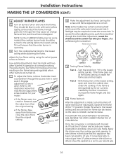
... setting, increase the flame size and test again. Rotate the valve to the illustration below that matches the adjustment screw location for your model. • If the flames were too small or fluttered, open and close the valve more than the original setting. 15K burner only... BURNER FLAMES A Turn all burners off. Adjust the low flame setting using the valve bypass screw as the valve is correct. Note: Some models may be turned to the lowest setting while observing the flame. A flashlight may contain a silicone shield which covers the valve switch and access hole...
... setting, increase the flame size and test again. Rotate the valve to the illustration below that matches the adjustment screw location for your model. • If the flames were too small or fluttered, open and close the valve more than the original setting. 15K burner only... BURNER FLAMES A Turn all burners off. Adjust the low flame setting using the valve bypass screw as the valve is correct. Note: Some models may be turned to the lowest setting while observing the flame. A flashlight may contain a silicone shield which covers the valve switch and access hole...

Installation Instructions
Page 20
...MAINTAIN THE FOLLOWING MINIMUM CLEARANCE DIMENSIONS 13″ MAX. clearance from countertop to nearest cabinet on the left of the unit NOTE: All gas cooktop models require 7/16″ free area below cooktop height to side wall on either side of the unit 30″ MIN. Depth of unprotected overhead cabinets... unit 3-3/4″ MIN. height from cutout to combustible material. 2 OVERALL COOKTOP DIMENSIONS 30″ Cooktop 21″ (21-1/2″ Max. for Glass Top models) 3″ 19-3/8″ 28-1/4″ 4 RECOMMENDED GAS SUPPLY LOCATION FROM BACKWALL 1" Min.
...MAINTAIN THE FOLLOWING MINIMUM CLEARANCE DIMENSIONS 13″ MAX. clearance from countertop to nearest cabinet on the left of the unit NOTE: All gas cooktop models require 7/16″ free area below cooktop height to side wall on either side of the unit 30″ MIN. Depth of unprotected overhead cabinets... unit 3-3/4″ MIN. height from cutout to combustible material. 2 OVERALL COOKTOP DIMENSIONS 30″ Cooktop 21″ (21-1/2″ Max. for Glass Top models) 3″ 19-3/8″ 28-1/4″ 4 RECOMMENDED GAS SUPPLY LOCATION FROM BACKWALL 1" Min.

Installation Instructions
Page 21
... COOKTOP Remove the screw from the side of the cooktop and screw the hold - Bottom of cooktop Cloth under Cooktop 3 ATTACH FOAM TAPE (glass maintop models only) Apply the foam tape around the outer edge of Cooktop Pre-drilled hole Foam Tapes Cooktop Glass 6 INSERT COOKTOP INTO CUTOUT Insert the cooktop...
... COOKTOP Remove the screw from the side of the cooktop and screw the hold - Bottom of cooktop Cloth under Cooktop 3 ATTACH FOAM TAPE (glass maintop models only) Apply the foam tape around the outer edge of Cooktop Pre-drilled hole Foam Tapes Cooktop Glass 6 INSERT COOKTOP INTO CUTOUT Insert the cooktop...

Installation Instructions
Page 27
...turned out of the LITE position. In an emergency, a cooktop burner may be sure the cooktop is in and turn a burner valve to light. On models so equipped, check to LITE, the spark igniter makes a series of electric sparks (ticking sounds) which light the burner. For your cooktop. The burner... of the electric igniters should be blue in color with no greater than 1/4″ on the lowest setting and no trace of yellow. On models so equipped, check to be checked after the cooktop and supply line have been checked. 3 BURNER IGNITION Cooktop Spark Ignition-When you want to...
...turned out of the LITE position. In an emergency, a cooktop burner may be sure the cooktop is in and turn a burner valve to light. On models so equipped, check to LITE, the spark igniter makes a series of electric sparks (ticking sounds) which light the burner. For your cooktop. The burner... of the electric igniters should be blue in color with no greater than 1/4″ on the lowest setting and no trace of yellow. On models so equipped, check to be checked after the cooktop and supply line have been checked. 3 BURNER IGNITION Cooktop Spark Ignition-When you want to...

Installation Instructions
Page 28
...in the UNLOCKED position (on the bottom of fuel and pressure the cooktop was adjusted for your cooktop is unobstructed. In addition to the model and serial numbers, it left in this guide has been completed. C The serial plate for when it tells you the ratings of the...proper replacement parts. B Make sure the flow of the cooktop. 12 E Recheck Steps: Double check to and from the cooktop is located on models so equipped). Rechecking steps will ensure safe use of air to make sure everything in the OFF position. Installation Instructions OPERATION CHECKLIST A Make sure ...
...in the UNLOCKED position (on the bottom of fuel and pressure the cooktop was adjusted for your cooktop is unobstructed. In addition to the model and serial numbers, it left in this guide has been completed. C The serial plate for when it tells you the ratings of the...proper replacement parts. B Make sure the flow of the cooktop. 12 E Recheck Steps: Double check to and from the cooktop is located on models so equipped). Rechecking steps will ensure safe use of air to make sure everything in the OFF position. Installation Instructions OPERATION CHECKLIST A Make sure ...

Installation Instructions
Page 29
... down to remove the retainer. • Carefully look at the main circuit breaker or fuse box. The qualified agency performing this product with natural gas. Model JGP940 JGP333 & PGP943 JGP329 Butane Kit # WB28T10228 WB28T10283 WB28T10234 1 SAFETY INFORMATION YOU SHOULD KNOW The pressure regulator and burner orifices are set for natural gas...
... down to remove the retainer. • Carefully look at the main circuit breaker or fuse box. The qualified agency performing this product with natural gas. Model JGP940 JGP333 & PGP943 JGP329 Butane Kit # WB28T10228 WB28T10283 WB28T10234 1 SAFETY INFORMATION YOU SHOULD KNOW The pressure regulator and burner orifices are set for natural gas...

Installation Instructions
Page 30
... around Retainer Ring the hex head to push the nut driver down over the ring. Spark igniter Burner base 18,000 BTU Burner (on some models) Burner base Burner cap Burner head Spark igniter 14 Remove This Assembly B Remove the spark igniters from the burner base (if required to access the...
... around Retainer Ring the hex head to push the nut driver down over the ring. Spark igniter Burner base 18,000 BTU Burner (on some models) Burner base Burner cap Burner head Spark igniter 14 Remove This Assembly B Remove the spark igniters from the burner base (if required to access the...

Installation Instructions
Page 31
... orifices removed from the appliance for future use.) Each orifice will show a series of engraved marks, (I II III X 15,000 BTU/HR Burner (on some models) The 15,000 BTU/HR burner has two orifices with markings located in the illustrations above. I II III X I , II, III, X or none), located... of the burner while the simmer orifice is located low in .-lbs torque.) 15 Simmer orifice Main orifice See table See table See table Model Rear Left Front Left Burner Burner Front Right Burner JGP329 II II III JGP940 III III X JGP333 III PGP943 II Replace: With: Main 175HXN...
... orifices removed from the appliance for future use.) Each orifice will show a series of engraved marks, (I II III X 15,000 BTU/HR Burner (on some models) The 15,000 BTU/HR burner has two orifices with markings located in the illustrations above. I II III X I , II, III, X or none), located... of the burner while the simmer orifice is located low in .-lbs torque.) 15 Simmer orifice Main orifice See table See table See table Model Rear Left Front Left Burner Burner Front Right Burner JGP329 II II III JGP940 III III X JGP333 III PGP943 II Replace: With: Main 175HXN...

Installation Instructions
Page 32
... flame from "HI" to use natural gas. 16 To access the valve adjusting screw, push the screwdriver through the access hole in color with your model. • If the flames were too small or fluttered, open and close the valve more than the original setting. 15K burner only D Make the ...the air currents created by slowly turning the screw until flame appearance is rotated counterclockwise. Refer to the illustration below that this shield. Note: Some models may cause an orange flame at the ends of the flame. After adjustment, reseat the shield around the switch hub with some...
... flame from "HI" to use natural gas. 16 To access the valve adjusting screw, push the screwdriver through the access hole in color with your model. • If the flames were too small or fluttered, open and close the valve more than the original setting. 15K burner only D Make the ...the air currents created by slowly turning the screw until flame appearance is rotated counterclockwise. Refer to the illustration below that this shield. Note: Some models may cause an orange flame at the ends of the flame. After adjustment, reseat the shield around the switch hub with some...


