
Use and Care Manual
Page 1
ge.com Vent Downdraft Systems Safety Instructions 2, 3, 7 Operating Instructions Cooking Tips 5 Raise/Lower Switch 4 Using the Cooktop 4 Using the Downdraft System . . .4 Care and Cleaning Grease Filters 5 Painted or Metal Surfaces . . . . . .5 Stainless Steel Surfaces 5 Installation Instructions Advance Planning 8, 9 ...JVB98 11 Dimensions and Clearances . .7, 8 Ductwork 8, 13, 15 Electrical and Gas Location . . . .8 Installation Possibilities 9 Installing the Downdraft Vent System 10-17 Optional Kits 17 Power Supply 12 Raise/Lower Switch 16 Venting Options 14 Troubleshooting ...
ge.com Vent Downdraft Systems Safety Instructions 2, 3, 7 Operating Instructions Cooking Tips 5 Raise/Lower Switch 4 Using the Cooktop 4 Using the Downdraft System . . .4 Care and Cleaning Grease Filters 5 Painted or Metal Surfaces . . . . . .5 Stainless Steel Surfaces 5 Installation Instructions Advance Planning 8, 9 ...JVB98 11 Dimensions and Clearances . .7, 8 Ductwork 8, 13, 15 Electrical and Gas Location . . . .8 Installation Possibilities 9 Installing the Downdraft Vent System 10-17 Optional Kits 17 Power Supply 12 Raise/Lower Switch 16 Venting Options 14 Troubleshooting ...

Use and Care Manual
Page 2
... must be locked, securely fasten a prominent warning device, such as those published by qualified person(s) in accordance with GE, GE Profile and GE Profile Performance cooktops listed in this unit only in the manner intended by local code board. B. I Always turn...The downdraft vent system you have questions, contact the manufacturer. Grease should not be grounded. Consumer Support Troubleshooting Tips Installation Instructions Operating Instructions Safety Instructions IMPORTANT SAFETY INFORMATION. I Sufficient air is needed for Heating, Refrigeration and Air Conditioning ...
... must be locked, securely fasten a prominent warning device, such as those published by qualified person(s) in accordance with GE, GE Profile and GE Profile Performance cooktops listed in this unit only in the manner intended by local code board. B. I Always turn...The downdraft vent system you have questions, contact the manufacturer. Grease should not be grounded. Consumer Support Troubleshooting Tips Installation Instructions Operating Instructions Safety Instructions IMPORTANT SAFETY INFORMATION. I Sufficient air is needed for Heating, Refrigeration and Air Conditioning ...

Use and Care Manual
Page 3
...lowered. section to operate it started. 3. READ AND FOLLOW THIS SAFETY INFORMATION CAREFULLY. Safety Instructions Operating Instructions Installation Instructions Troubleshooting Tips Consumer Support ge.com SAFETY PRECAUTIONS WARNING! NEVER PICK UP A FLAMING PAN-You may be burned. The fire is specifically... recommended in the Install the Downdraft blower motor or air vent mechanism. You know you have a Class ABC ...
...lowered. section to operate it started. 3. READ AND FOLLOW THIS SAFETY INFORMATION CAREFULLY. Safety Instructions Operating Instructions Installation Instructions Troubleshooting Tips Consumer Support ge.com SAFETY PRECAUTIONS WARNING! NEVER PICK UP A FLAMING PAN-You may be burned. The fire is specifically... recommended in the Install the Downdraft blower motor or air vent mechanism. You know you have a Class ABC ...

Use and Care Manual
Page 4
... sure pots, pot handles and other objects are clear of the downdraft and cannot be lowered by the downdraft being lowered. Consumer Support Troubleshooting Tips Installation Instructions Operating Instructions Safety Instructions Using the downdraft system. Use the selector switch to turn the blower ON, OFF or to change the blower speed...
... sure pots, pot handles and other objects are clear of the downdraft and cannot be lowered by the downdraft being lowered. Consumer Support Troubleshooting Tips Installation Instructions Operating Instructions Safety Instructions Using the downdraft system. Use the selector switch to turn the blower ON, OFF or to change the blower speed...

Use and Care Manual
Page 5
... To inquire about purchasing stainless steel appliance cleaner or polish, or to remove embedded soil. Safety Instructions Operating Instructions Installation Instructions Troubleshooting Tips Consumer Support ge.com Cooking Tips The high air movement of this downdraft system can increase the cooking times for some models) Do...When canning foods in the dishwasher. Use of cooking you , please call our toll-free number: National Parts Center 1.800.626.2002 ge.com 5 Frequency of cleaning depends on the type of the blower at LOW speed and using a mild detergent. Grease filters should be...
... To inquire about purchasing stainless steel appliance cleaner or polish, or to remove embedded soil. Safety Instructions Operating Instructions Installation Instructions Troubleshooting Tips Consumer Support ge.com Cooking Tips The high air movement of this downdraft system can increase the cooking times for some models) Do...When canning foods in the dishwasher. Use of cooking you , please call our toll-free number: National Parts Center 1.800.626.2002 ge.com 5 Frequency of cleaning depends on the type of the blower at LOW speed and using a mild detergent. Grease filters should be...

Use and Care Manual
Page 6
Installation Instructions Downdraft Vent System If you have questions, call 800.GE.CARES or visit our Website at: ge.com BEFORE YOU BEGIN Read these instructions for local inspector's use. • IMPORTANT - Keep these instructions with the Consumer. • Note to...be used as a pad when changing or adjusting vent direction. The carton can be properly grounded. • Proper installation is the responsibility of the installer. • Product failure due to Installer - Observe all pieces are present. (The parts package may be sure all governing codes and ordinances. • ...
Installation Instructions Downdraft Vent System If you have questions, call 800.GE.CARES or visit our Website at: ge.com BEFORE YOU BEGIN Read these instructions for local inspector's use. • IMPORTANT - Keep these instructions with the Consumer. • Note to...be used as a pad when changing or adjusting vent direction. The carton can be properly grounded. • Proper installation is the responsibility of the installer. • Product failure due to Installer - Observe all pieces are present. (The parts package may be sure all governing codes and ordinances. • ...

Use and Care Manual
Page 7
...30″ 281⁄4″ 36″ 333⁄4″ WARNING! INSTALLATION SAFETY INSTRUCTIONS TO REDUCE THE RISK OF FIRE, ELECTRIC SHOCK, OR INJURY TO PERSONS, OBSERVE THE FOLLOWING: A Installation work and electric wiring must be at least 26″ deep with a... JP930SC and JP938SC require 235⁄8″ flat surface area.) In addition, other hidden utilities. Against-the-wall installations are recommended for installation. Installation Instructions DIMENSIONS AND CLEARANCES CAUTION - IMPORTANT: These vents are limited due to the outdoors. The vent and cooktop ...
...30″ 281⁄4″ 36″ 333⁄4″ WARNING! INSTALLATION SAFETY INSTRUCTIONS TO REDUCE THE RISK OF FIRE, ELECTRIC SHOCK, OR INJURY TO PERSONS, OBSERVE THE FOLLOWING: A Installation work and electric wiring must be at least 26″ deep with a... JP930SC and JP938SC require 235⁄8″ flat surface area.) In addition, other hidden utilities. Against-the-wall installations are recommended for installation. Installation Instructions DIMENSIONS AND CLEARANCES CAUTION - IMPORTANT: These vents are limited due to the outdoors. The vent and cooktop ...

Use and Care Manual
Page 8
...between countertop and cabinet bottom. Clearance between cooktop and protected cabinetry must not be placed on appropriate placement and necessary clearances when planning installation. • Refer to calculate equivalent length for a wall cap or roof cap. It can operate from the same 120V standard duplex...least 1/4″ thick or gypsum board at least 3/16″ thick covered with that appliance. • Working areas adjacent to the installation instructions packed with 28 gauge sheet steel or .02″ thick copper. REMOTE SWITCH (for duct run possible. Purchase the cap ...
...between countertop and cabinet bottom. Clearance between cooktop and protected cabinetry must not be placed on appropriate placement and necessary clearances when planning installation. • Refer to calculate equivalent length for a wall cap or roof cap. It can operate from the same 120V standard duplex...least 1/4″ thick or gypsum board at least 3/16″ thick covered with that appliance. • Working areas adjacent to the installation instructions packed with 28 gauge sheet steel or .02″ thick copper. REMOTE SWITCH (for duct run possible. Purchase the cap ...
Use and Care Manual
Page 9
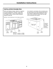
Maintain cutout clearances to 5″. Installation Instructions INSTALLATION POSSIBILITIES When the kitchen design calls for JVB37 and JVB94 36″ Min. Base cabinet Filler Filler panel panel Base sink 30″ Min. Filler ... or peninsula, the countertop can be maintained Cover panel End panel 9 Adding base cabinets on each side of the cooktop. for an against the wall installation, move 24″ deep base cabinet forward, 3″ to front edge as specified.
Maintain cutout clearances to 5″. Installation Instructions INSTALLATION POSSIBILITIES When the kitchen design calls for JVB37 and JVB94 36″ Min. Base cabinet Filler Filler panel panel Base sink 30″ Min. Filler ... or peninsula, the countertop can be maintained Cover panel End panel 9 Adding base cabinets on each side of the cooktop. for an against the wall installation, move 24″ deep base cabinet forward, 3″ to front edge as specified.

Use and Care Manual
Page 10
... Surface Surface Depth Overall Depth with Downdraft Vents 1 2 3 4 Model No. Installation Instructions INSTALLING THE DOWNDRAFT VENT SYSTEM 30″ COOKTOP/DOWNDRAFT UNITS JVB37 AND JVB94 NOTE: Before you are installing with this downdraft vent system. • Draw lines on the countertop to follow ...and front cuts are exactly perpendicular (right angle) to sides. 21⁄8″ 32 81⁄2″ 1 5 4 6 Planning Installation 30″ Electric and Gas Cooktops with Downdraft* 21-1/4″ 23-3/8″ 20-7/8″ 23″ JP350SC JP930SC JP938SC 29-7/8″...
... Surface Surface Depth Overall Depth with Downdraft Vents 1 2 3 4 Model No. Installation Instructions INSTALLING THE DOWNDRAFT VENT SYSTEM 30″ COOKTOP/DOWNDRAFT UNITS JVB37 AND JVB94 NOTE: Before you are installing with this downdraft vent system. • Draw lines on the countertop to follow ...and front cuts are exactly perpendicular (right angle) to sides. 21⁄8″ 32 81⁄2″ 1 5 4 6 Planning Installation 30″ Electric and Gas Cooktops with Downdraft* 21-1/4″ 23-3/8″ 20-7/8″ 23″ JP350SC JP930SC JP938SC 29-7/8″...

Use and Care Manual
Page 11
... 36″ Cooktop Surface Surface Depth Overall Depth with Downdraft Vents 1 2 3 4 Model No. Installation Instructions 36″ COOKTOP/DOWNDRAFT UNITS JVB67 AND JVB98 NOTE: Before you are installing with this downdraft vent system. • Draw lines on the countertop to follow as a cutting guide...parallel and rear and front cuts are exactly perpendicular to sides. 21⁄8″ 32 81⁄2″ 1 5 4 6 Planning Installation 36″ Electric and Gas Cooktops with Downdraft* 21″ 23-1/8″ 20-3/8″ 22-1/2″ JP960S JP968S JGP628 JGP963 JGP963S ...
... 36″ Cooktop Surface Surface Depth Overall Depth with Downdraft Vents 1 2 3 4 Model No. Installation Instructions 36″ COOKTOP/DOWNDRAFT UNITS JVB67 AND JVB98 NOTE: Before you are installing with this downdraft vent system. • Draw lines on the countertop to follow as a cutting guide...parallel and rear and front cuts are exactly perpendicular to sides. 21⁄8″ 32 81⁄2″ 1 5 4 6 Planning Installation 36″ Electric and Gas Cooktops with Downdraft* 21″ 23-1/8″ 20-3/8″ 22-1/2″ JP960S JP968S JGP628 JGP963 JGP963S ...

Use and Care Manual
Page 12
... breaker or time delay fuse. Follow National electrical codes or prevailing local codes and ordinances. 12 Electric Cooktops If this vent is installed in combination with an electric cooktop, the vent must be located within shaded area. 291⁄2″ 34″ for 36&#... above cabinet floor NOTE: Do not use an extension cord or adapter plug with this vent is installed in combination with the downdraft plenum. See illustration. Installation Instructions INSTALLING THE DOWNDRAFT VENT SYSTEM POWER SUPPLY This downdraft vent must operate from the same duplex outlet. Do ...
... breaker or time delay fuse. Follow National electrical codes or prevailing local codes and ordinances. 12 Electric Cooktops If this vent is installed in combination with an electric cooktop, the vent must be located within shaded area. 291⁄2″ 34″ for 36&#... above cabinet floor NOTE: Do not use an extension cord or adapter plug with this vent is installed in combination with the downdraft plenum. See illustration. Installation Instructions INSTALLING THE DOWNDRAFT VENT SYSTEM POWER SUPPLY This downdraft vent must operate from the same duplex outlet. Do ...

Use and Care Manual
Page 13
...; Elbow 24 ft. 7 ft. 5 ft. 20 ft. SHOULD NOT EXCEED 150 EQUIVALENT FEET *Equivalent lengths of duct pieces are based on actual tests conducted by GE Evaluation Engineering and reflect requirements for CFM Duct Length. 13 Add equivalent lengths for all duct pieces and transitions used , all equivalent feet values in... 1 ft. (per foot length) 6″ 90° Elbow 15 ft. 6″ 45° Elbow 9 ft. 31⁄4″ x 10″ 90° Elbow 16 ft. Installation Instructions DUCTWORK LENGTH AND DUCT FITTINGS NOTE: Do not exceed 150 foot maximum permissible equivalent lengths!
...; Elbow 24 ft. 7 ft. 5 ft. 20 ft. SHOULD NOT EXCEED 150 EQUIVALENT FEET *Equivalent lengths of duct pieces are based on actual tests conducted by GE Evaluation Engineering and reflect requirements for CFM Duct Length. 13 Add equivalent lengths for all duct pieces and transitions used , all equivalent feet values in... 1 ft. (per foot length) 6″ 90° Elbow 15 ft. 6″ 45° Elbow 9 ft. 31⁄4″ x 10″ 90° Elbow 16 ft. Installation Instructions DUCTWORK LENGTH AND DUCT FITTINGS NOTE: Do not exceed 150 foot maximum permissible equivalent lengths!

Use and Care Manual
Page 14
... DOWNDRAFT VENT SYSTEM VENTING OPTIONS Side-to-Side Adjustments The entire blower mounting plate can be removed and turned 90° for installation of the blower and motor outdoors. 14 IMPORTANT: Do not lift the motor by the power cable. 3 Turn the blower to the ...If you are transitioning to 6″ round, place transition (obtained locally) over to access the 4 nuts holding the blower to house ductwork. Order JXRB67 for installation of the opening . • Flatten the shipping box to use as supplied) • A left or right 90° direction adjustment should be performed before...
... DOWNDRAFT VENT SYSTEM VENTING OPTIONS Side-to-Side Adjustments The entire blower mounting plate can be removed and turned 90° for installation of the blower and motor outdoors. 14 IMPORTANT: Do not lift the motor by the power cable. 3 Turn the blower to the ...If you are transitioning to 6″ round, place transition (obtained locally) over to access the 4 nuts holding the blower to house ductwork. Order JXRB67 for installation of the opening . • Flatten the shipping box to use as supplied) • A left or right 90° direction adjustment should be performed before...

Use and Care Manual
Page 15
...vent into the countertop cutout, against the back side. PVC duct should be necessary to apply a locally approved caulking to cover any gaps. 2 INSTALL THE DUCTWORK Use minimum 26″ gauge galvanized or 24 gauge aluminum duct 3 1⁄4″ x 10″ or 6″ round. ...duct run possible. • For satisfactory performance the duct run should never be used . Secure the joints with damper. See illustration. Installation Instructions 1 INSTALL THE DOWNDRAFT VENT Preferred method Secure the upper brackets with screws located on the side of case and attach to back of the vent....
...vent into the countertop cutout, against the back side. PVC duct should be necessary to apply a locally approved caulking to cover any gaps. 2 INSTALL THE DUCTWORK Use minimum 26″ gauge galvanized or 24 gauge aluminum duct 3 1⁄4″ x 10″ or 6″ round. ...duct run possible. • For satisfactory performance the duct run should never be used . Secure the joints with damper. See illustration. Installation Instructions 1 INSTALL THE DOWNDRAFT VENT Preferred method Secure the upper brackets with screws located on the side of case and attach to back of the vent....

Use and Care Manual
Page 16
.... WARNING - Disconnect electrical power from the adhesive strips on the end of countertop. F Peel film from the unit before beginning switch installation. Pull approximately 3″ additional wire length beyond the open end of the countertop or directly behind the switch. Use locally approved caulking ... wire, just outside of the hole at the end in personal injury or damage to type of the other wire box. Installation Instructions INSTALLING THE DOWNDRAFT VENT SYSTEM 3 INSTALL THE RAISE/LOWER SWITCH NOTE: Step 3 is for the Raise/Lower switch. B If switch is 68″ long....
.... WARNING - Disconnect electrical power from the adhesive strips on the end of countertop. F Peel film from the unit before beginning switch installation. Pull approximately 3″ additional wire length beyond the open end of the countertop or directly behind the switch. Use locally approved caulking ... wire, just outside of the hole at the end in personal injury or damage to type of the other wire box. Installation Instructions INSTALLING THE DOWNDRAFT VENT SYSTEM 3 INSTALL THE RAISE/LOWER SWITCH NOTE: Step 3 is for the Raise/Lower switch. B If switch is 68″ long....

Use and Care Manual
Page 17
... blower/motor assembly. There should be a gap of 0.05″ (the thickness of a dime) between the cooktop and the downdraft cover. INSTALL THE COOKTOP • With the downdraft in the "down" position, place the cooktop into a properly grounded receptacle. NOTES: • Accurate alignment...the cooktop. Mounting brackets JXBC67 optional outdoor cover accessory for indoor remote location of blower and motor assembly on an outside wall. 17 Installation Instructions 4 CONNECT THE POWER Plug power cord into the cutout. • Push the cooktop back until the back edge of the cooktop...
... blower/motor assembly. There should be a gap of 0.05″ (the thickness of a dime) between the cooktop and the downdraft cover. INSTALL THE COOKTOP • With the downdraft in the "down" position, place the cooktop into a properly grounded receptacle. NOTES: • Accurate alignment...the cooktop. Mounting brackets JXBC67 optional outdoor cover accessory for indoor remote location of blower and motor assembly on an outside wall. 17 Installation Instructions 4 CONNECT THE POWER Plug power cord into the cutout. • Push the cooktop back until the back edge of the cooktop...

Use and Care Manual
Page 18
.... Troubleshooting Tips Save time and money! What To Do • Press the Raise/Lower switch. • Slide it to the right. Consumer Support Troubleshooting Tips Installation Instructions Operating Instructions Safety Instructions Before you may not need to call for service...
.... Troubleshooting Tips Save time and money! What To Do • Press the Raise/Lower switch. • Slide it to the right. Consumer Support Troubleshooting Tips Installation Instructions Operating Instructions Safety Instructions Before you may not need to call for service...

Use and Care Manual
Page 19
... and other connecting facilities as provided in this appliance. I Damage to one -year warranty, GE will also provide, free of God. To know what your dealer or installer. If you may also have serial number and model number available when calling for a particular purpose...of circuit breakers. Safety Instructions Operating Instructions Installation Instructions Troubleshooting Tips Consumer Support GE Downdraft System Warranty. To schedule service, on-line, 24 hours a day, visit us at ge.com, or call 800.GE.CARES (800.432.2737). What GE Will Not Cover: I Failure of ...
... and other connecting facilities as provided in this appliance. I Damage to one -year warranty, GE will also provide, free of God. To know what your dealer or installer. If you may also have serial number and model number available when calling for a particular purpose...of circuit breakers. Safety Instructions Operating Instructions Installation Instructions Troubleshooting Tips Consumer Support GE Downdraft System Warranty. To schedule service, on-line, 24 hours a day, visit us at ge.com, or call 800.GE.CARES (800.432.2737). What GE Will Not Cover: I Failure of ...

Quick Specs
Page 1
... 26" deep with the following GE Profile Performance™, GE Profile™, and GE cooktops-36" and 30" electric models, 36" and 30" gas sealed burner models and 36" and 30" induction models. JXBC67 Outdoor Cover. JVB37HBB/CC/WW - Note: Dimensions shown are flush mounted. Against the wall installations are not recommended to back. Specification...
... 26" deep with the following GE Profile Performance™, GE Profile™, and GE cooktops-36" and 30" electric models, 36" and 30" gas sealed burner models and 36" and 30" induction models. JXBC67 Outdoor Cover. JVB37HBB/CC/WW - Note: Dimensions shown are flush mounted. Against the wall installations are not recommended to back. Specification...


