
Use and Care Manual
Page 1
ge.com Vent Downdraft Systems Safety Instructions 2, 3, 7 Operating Instructions Cooking Tips 5 Raise/Lower Switch 4 Using the Cooktop 4 Using the Downdraft System . . .4 Care and Cleaning Grease Filters 5 ... 11 Dimensions and Clearances . .7, 8 Ductwork 8, 13, 15 Electrical and Gas Location . . . .8 Installation Possibilities 9 Installing the Downdraft Vent System 10-17 Optional Kits 17 Power Supply 12 Raise/Lower Switch 16 Venting Options 14 Troubleshooting Tips 18 Consumer Support Consumer Support 20 Warranty 19 Owner's Manual & Installation Instructions JVB37 JVB67 JVB94...
ge.com Vent Downdraft Systems Safety Instructions 2, 3, 7 Operating Instructions Cooking Tips 5 Raise/Lower Switch 4 Using the Cooktop 4 Using the Downdraft System . . .4 Care and Cleaning Grease Filters 5 ... 11 Dimensions and Clearances . .7, 8 Ductwork 8, 13, 15 Electrical and Gas Location . . . .8 Installation Possibilities 9 Installing the Downdraft Vent System 10-17 Optional Kits 17 Power Supply 12 Raise/Lower Switch 16 Venting Options 14 Troubleshooting Tips 18 Consumer Support Consumer Support 20 Warranty 19 Owner's Manual & Installation Instructions JVB37 JVB67 JVB94...

Use and Care Manual
Page 2
...Refrigeration and Air Conditioning Engineers (ASHRAE), and the local code authorities. READ ALL INSTRUCTIONS BEFORE USING. I Ducted fans must be vented to exhaust hazardous or explosive materials and vapors. Follow the heating equipment manufacturer's guideline and safety standards such as a tag, ... published by qualified person(s) in the manner intended by local code board. Use this manual must be used with GE, GE Profile and GE Profile Performance cooktops listed in this unit only in accordance with all applicable codes and standards, including fire-rated construction...
...Refrigeration and Air Conditioning Engineers (ASHRAE), and the local code authorities. READ ALL INSTRUCTIONS BEFORE USING. I Ducted fans must be vented to exhaust hazardous or explosive materials and vapors. Follow the heating equipment manufacturer's guideline and safety standards such as a tag, ... published by qualified person(s) in the manner intended by local code board. Use this manual must be used with GE, GE Profile and GE Profile Performance cooktops listed in this unit only in accordance with all applicable codes and standards, including fire-rated construction...

Use and Care Manual
Page 3
...an exit. *Based on "Kitchen Fire safety Tips" published by NFPA. Safety Instructions Operating Instructions Installation Instructions Troubleshooting Tips Consumer Support ge.com SAFETY PRECAUTIONS WARNING! All other servicing should be burned. DO NOT USE WATER, including wet dishcloths or towels-a violent steam... explosion will result. The fire is specifically recommended in the Install the Downdraft blower motor or air vent mechanism. You know you have a Class ABC extinguisher, and you already know how to service components such as the first...
...an exit. *Based on "Kitchen Fire safety Tips" published by NFPA. Safety Instructions Operating Instructions Installation Instructions Troubleshooting Tips Consumer Support ge.com SAFETY PRECAUTIONS WARNING! All other servicing should be burned. DO NOT USE WATER, including wet dishcloths or towels-a violent steam... explosion will result. The fire is specifically recommended in the Install the Downdraft blower motor or air vent mechanism. You know you have a Class ABC extinguisher, and you already know how to service components such as the first...

Use and Care Manual
Page 4
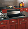
... (30″ models only) Turn the downdraft blower ON by again pressing the raise/lower switch at the top right of the vent. This switch may be lowered by pressing the raise/lower switch located at the top right side of the downdraft cover when it is...: Be careful when raising or lowering the downdraft. The air vent will automatically go off when the vent is being raised. The vent may vary. Be sure pots, pot handles and other objects are clear of the vent. Consumer Support Troubleshooting Tips Installation Instructions Operating Instructions Safety Instructions Using...
... (30″ models only) Turn the downdraft blower ON by again pressing the raise/lower switch at the top right of the vent. This switch may be lowered by pressing the raise/lower switch located at the top right side of the downdraft cover when it is...: Be careful when raising or lowering the downdraft. The air vent will automatically go off when the vent is being raised. The vent may vary. Be sure pots, pot handles and other objects are clear of the vent. Consumer Support Troubleshooting Tips Installation Instructions Operating Instructions Safety Instructions Using...

Use and Care Manual
Page 6
... is the responsibility of the installer. • Product failure due to Installer - Installation Instructions Downdraft Vent System If you have questions, call 800.GE.CARES or visit our Website at: ge.com BEFORE YOU BEGIN Read these instructions with the Consumer. • Note to Consumer - This ...appliance must be used as a pad when changing or adjusting vent direction. Observe all models) (4) Remote raise/lower ...
... is the responsibility of the installer. • Product failure due to Installer - Installation Instructions Downdraft Vent System If you have questions, call 800.GE.CARES or visit our Website at: ge.com BEFORE YOU BEGIN Read these instructions with the Consumer. • Note to Consumer - This ...appliance must be used as a pad when changing or adjusting vent direction. Observe all models) (4) Remote raise/lower ...

Use and Care Manual
Page 7
...the countertop must be considered. • See specific cutout illustrations with your cooktop model to countertop depth requirements. IMPORTANT: These vents are limited due to determine requirements. • A countertop with all applicable codes and standards, including fire-rated construction. ... into wall or ceiling, do not damage electrical wiring and other clearances to the outdoors. B Ducted fans must be vented to the front edge of fire, use only metal ductwork. Installation Instructions DIMENSIONS AND CLEARANCES CAUTION - INSTALLATION SAFETY INSTRUCTIONS TO...
...the countertop must be considered. • See specific cutout illustrations with your cooktop model to countertop depth requirements. IMPORTANT: These vents are limited due to determine requirements. • A countertop with all applicable codes and standards, including fire-rated construction. ... into wall or ceiling, do not damage electrical wiring and other clearances to the outdoors. B Ducted fans must be vented to the front edge of fire, use only metal ductwork. Installation Instructions DIMENSIONS AND CLEARANCES CAUTION - INSTALLATION SAFETY INSTRUCTIONS TO...

Use and Care Manual
Page 8
...REMOTE SWITCH (for duct run possible. Use cabinets no more than 24″. COOKTOP ELECTRICAL AND GAS LOCATION Plan the placement of the vent/cooktop cutout. 8 Plan to the outside of the electrical outlet and gas (if used above cooktop. EXCEPTION: Installation of a listed ...surface: Installation must conform with that appliance. • Working areas adjacent to the installation instructions packed with local codes. DUCTWORK Prepare ductwork to vent to use 31⁄4″ x 10″ ductwork. Refer to Duct Fittings chart to 6″ round. • Ductwork MUST be less...
...REMOTE SWITCH (for duct run possible. Use cabinets no more than 24″. COOKTOP ELECTRICAL AND GAS LOCATION Plan the placement of the vent/cooktop cutout. 8 Plan to the outside of the electrical outlet and gas (if used above cooktop. EXCEPTION: Installation of a listed ...surface: Installation must conform with that appliance. • Working areas adjacent to the installation instructions packed with local codes. DUCTWORK Prepare ductwork to vent to use 31⁄4″ x 10″ ductwork. Refer to Duct Fittings chart to 6″ round. • Ductwork MUST be less...

Use and Care Manual
Page 10
JP326 JP340 JP350 JP930 JP931 JP938 JP939 Overall Width 30-1/4″ 29-3/4″ Cooktop Surface Surface Depth Overall Depth with Downdraft Vents 1 2 3 4 Model No. Identify the cutout illustration for the cooktop model you begin, measure and mark Dimension 3 to Front Edge** 2-1/2″ 2-1/2″ 2-1/2&#...; 21-5/8″ 23-1/8″ 23-1/8″ 23-1/8″ 23-3/8″ 23-3/4″ **Includes 1/8″ gap between cooktop and vent trim **Required to maintain UL or AGA approvals Minimum Setback Cutout to ensure that adequate flat countertop surface is available.
JP326 JP340 JP350 JP930 JP931 JP938 JP939 Overall Width 30-1/4″ 29-3/4″ Cooktop Surface Surface Depth Overall Depth with Downdraft Vents 1 2 3 4 Model No. Identify the cutout illustration for the cooktop model you begin, measure and mark Dimension 3 to Front Edge** 2-1/2″ 2-1/2″ 2-1/2&#...; 21-5/8″ 23-1/8″ 23-1/8″ 23-1/8″ 23-3/8″ 23-3/4″ **Includes 1/8″ gap between cooktop and vent trim **Required to maintain UL or AGA approvals Minimum Setback Cutout to ensure that adequate flat countertop surface is available.

Use and Care Manual
Page 11
...21-1/16″ 23-1/8″ 23-1/8″ 23-1/8″ 23-1/8″ 22-9/16″ 23-3/16″ **Includes 1/8″ gap between cooktop and vent trim **Required to maintain UL or AGA approvals Minimum Setback Cutout to sides. 21⁄8″ 32 81⁄2″ 1 5 4 6 Planning Installation... 36″ Electric and Gas Cooktops with this downdraft vent system. • Draw lines on the countertop to follow as a cutting guide. • Make sure sides of the opening are parallel and ...
...21-1/16″ 23-1/8″ 23-1/8″ 23-1/8″ 23-1/8″ 22-9/16″ 23-3/16″ **Includes 1/8″ gap between cooktop and vent trim **Required to maintain UL or AGA approvals Minimum Setback Cutout to sides. 21⁄8″ 32 81⁄2″ 1 5 4 6 Planning Installation... 36″ Electric and Gas Cooktops with this downdraft vent system. • Draw lines on the countertop to follow as a cutting guide. • Make sure sides of the opening are parallel and ...

Use and Care Manual
Page 12
... a separate 120V outlet. The receptacle cannot be placed on the right side wall. Do not leave gas or electrical connections within reach of the vents' 2 foot power cord. • Locate the receptacle inside the cabinet on the back of the cabinet wall where it may interfere with this appliance.... Gas Cooktops If this vent is installed in combination with an electric cooktop, the vent must be located within shaded area. 291⁄2″ 34″ for 36″ models 281⁄2″ ...
... a separate 120V outlet. The receptacle cannot be placed on the right side wall. Do not leave gas or electrical connections within reach of the vents' 2 foot power cord. • Locate the receptacle inside the cabinet on the back of the cabinet wall where it may interfere with this appliance.... Gas Cooktops If this vent is installed in combination with an electric cooktop, the vent must be located within shaded area. 291⁄2″ 34″ for 36″ models 281⁄2″ ...

Use and Care Manual
Page 13
.... 13 SHOULD NOT EXCEED 150 EQUIVALENT FEET *Equivalent lengths of duct pieces are based on actual tests conducted by GE Evaluation Engineering and reflect requirements for good venting performance. Installation Instructions DUCTWORK LENGTH AND DUCT FITTINGS NOTE: Do not exceed 150 foot maximum permissible equivalent lengths! Duct...8243; Wall Cap with Damper Equivalent Length* 12 ft. 21 ft. 27 ft. 6″ Round Roof Cap 20 ft. 6″ Round Roof Vent 24 ft. DO NOT use flexible plastic ducting. The flexible metal duct should be straight and smooth and extended as much as possible.
.... 13 SHOULD NOT EXCEED 150 EQUIVALENT FEET *Equivalent lengths of duct pieces are based on actual tests conducted by GE Evaluation Engineering and reflect requirements for good venting performance. Installation Instructions DUCTWORK LENGTH AND DUCT FITTINGS NOTE: Do not exceed 150 foot maximum permissible equivalent lengths! Duct...8243; Wall Cap with Damper Equivalent Length* 12 ft. 21 ft. 27 ft. 6″ Round Roof Cap 20 ft. 6″ Round Roof Vent 24 ft. DO NOT use flexible plastic ducting. The flexible metal duct should be straight and smooth and extended as much as possible.

Use and Care Manual
Page 14
...blower left Discharge right 4 Reinstall the blower and mounting plate with the discharge outlet pointing straight down (as a pad. • Lay the vent on its back onto the pad. Order JXBC67 for installation of the opening . • Flatten the shipping box to the left or right ...the blower to use as supplied) • A left or right. To Locate the Ductwork Holes in the Cabinet Floor or Side Walls 1 Temporarily, put vent into the countertop opening . 3 If you are transitioning to 6″ round, place transition (obtained locally) over to access the 4 nuts holding the blower...
...blower left Discharge right 4 Reinstall the blower and mounting plate with the discharge outlet pointing straight down (as a pad. • Lay the vent on its back onto the pad. Order JXBC67 for installation of the opening . • Flatten the shipping box to the left or right ...the blower to use as supplied) • A left or right. To Locate the Ductwork Holes in the Cabinet Floor or Side Walls 1 Temporarily, put vent into the countertop opening . 3 If you are transitioning to 6″ round, place transition (obtained locally) over to access the 4 nuts holding the blower...

Use and Care Manual
Page 15
...8226; Always use appropriate roof or wall cap with self-tapping screws and apply duct tape around the joints to blower housing Place the downdraft vent into the countertop cutout, against the back side. Duct tape over seam and screw Airflow Screw • Install ductwork so the piece of ...nearest the downdraft unit slots INTO the next piece of cabinet Secure the lower brackets to ensure an airtight seal. 15 B Fasten 2 brackets to vent side and secure to the countertop supplied brackets. Attach brackets to slide screws on the bottom of equivalent lengths to cover any gaps. 2 INSTALL...
...8226; Always use appropriate roof or wall cap with self-tapping screws and apply duct tape around the joints to blower housing Place the downdraft vent into the countertop cutout, against the back side. Duct tape over seam and screw Airflow Screw • Install ductwork so the piece of ...nearest the downdraft unit slots INTO the next piece of cabinet Secure the lower brackets to ensure an airtight seal. 15 B Fasten 2 brackets to vent side and secure to the countertop supplied brackets. Attach brackets to slide screws on the bottom of equivalent lengths to cover any gaps. 2 INSTALL...

Use and Care Manual
Page 16
.... Thread the wire lead through the hole on the control box. Choose screws for interference between tiles. Installation Instructions INSTALLING THE DOWNDRAFT VENT SYSTEM 3 INSTALL THE RAISE/LOWER SWITCH NOTE: Step 3 is for the Raise/Lower switch. B Connect the mating wire connectors....Control box A Drill a 3/8″ hole into a tile surface, drill the hole between the switch cover, adjacent objects and cooktop/vent overlaps. Pull approximately 3″ additional wire length beyond the open end of countertop or use locally approved adhesive. WARNING - Check for...
.... Thread the wire lead through the hole on the control box. Choose screws for interference between tiles. Installation Instructions INSTALLING THE DOWNDRAFT VENT SYSTEM 3 INSTALL THE RAISE/LOWER SWITCH NOTE: Step 3 is for the Raise/Lower switch. B Connect the mating wire connectors....Control box A Drill a 3/8″ hole into a tile surface, drill the hole between the switch cover, adjacent objects and cooktop/vent overlaps. Pull approximately 3″ additional wire length beyond the open end of countertop or use locally approved adhesive. WARNING - Check for...

Use and Care Manual
Page 17
...) between the cooktop and the downdraft cover. There should be located below the cabinet floor. Use this downdraft vent. This may cause the downdraft cover to impact and damage the cooktop when the vent is raised and lowered. NOTES: • Accurate alignment of cooktop and downdraft is necessary to move rearward when... touches the front edge of the downdraft cover. • Using a dime as a thickness gauge, align the cooktop so that there is no interference when air vent is raised and lowered.
...) between the cooktop and the downdraft cover. There should be located below the cabinet floor. Use this downdraft vent. This may cause the downdraft cover to impact and damage the cooktop when the vent is raised and lowered. NOTES: • Accurate alignment of cooktop and downdraft is necessary to move rearward when... touches the front edge of the downdraft cover. • Using a dime as a thickness gauge, align the cooktop so that there is no interference when air vent is raised and lowered.

Use and Care Manual
Page 18
... switch not plugged in the OFF position. The blower control switch may be in . • Check all connections between the remote switch and vent body. 18 Raise/Lower switch did not engage lift motor. • Hold switch down for a couple of seconds to the right. What ...Slide it to activate motor. Review the chart below first and you call for service. Problem Fan does not work Vent does not rise Possible Causes The vent is not fully extended. Circuit breaker may not need to call for service... Consumer Support Troubleshooting Tips Installation Instructions Operating ...
... switch not plugged in the OFF position. The blower control switch may be in . • Check all connections between the remote switch and vent body. 18 Raise/Lower switch did not engage lift motor. • Hold switch down for a couple of seconds to the right. What ...Slide it to activate motor. Review the chart below first and you call for service. Problem Fan does not work Vent does not rise Possible Causes The vent is not fully extended. Circuit breaker may not need to call for service... Consumer Support Troubleshooting Tips Installation Instructions Operating ...

Quick Specs
Page 1
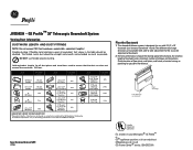
...with downdraft and cooktop. Refer to instructions packed with cooktops that are flush mounted. JXRB67 Indoor Remote Accessory. GE Profile™ 30" Telescopic Downdraft System Overall Dimensions (in inches) 30 Venting Options (in inches) Through the Floor In Cabinet Discharge (Down) 8-1/2 7-1/2 7-1/4 27 12-1/8 30"... remote location. Note: Dimensions shown are limited to dimension requirements. Optional accessory may be at GEAppliances.com or call GE Answer Center® service, 800.626.2000. Listed by Underwriters Laboratories For answers to the front edge of motor ...
...with downdraft and cooktop. Refer to instructions packed with cooktops that are flush mounted. JXRB67 Indoor Remote Accessory. GE Profile™ 30" Telescopic Downdraft System Overall Dimensions (in inches) 30 Venting Options (in inches) Through the Floor In Cabinet Discharge (Down) 8-1/2 7-1/2 7-1/4 27 12-1/8 30"... remote location. Note: Dimensions shown are limited to dimension requirements. Optional accessory may be at GEAppliances.com or call GE Answer Center® service, 800.626.2000. Listed by Underwriters Laboratories For answers to the front edge of motor ...
Quick Specs
Page 2
...; Transition 90°Elbow 8 ft. 33 ft. 2 ft. 2 ft. 4 ft. Left discharge (as possible. GE Profile™ 30" Telescopic Downdraft System Venting Duct Information DUCTWORK LENGTH AND DUCT FITTINGS NOTE: Do not exceed 150 foot maximum permissible equivalent lengths! Add equivalent lengths for use...10″ Transition 31⁄ 4″ x 10″ to 6″ Round Transition 6″ Round to -side adjustment for good venting performance. Two different discharge directions are based on actual tests conducted by Underwriters Laboratories For answers to ensure that the duct run does not...
...; Transition 90°Elbow 8 ft. 33 ft. 2 ft. 2 ft. 4 ft. Left discharge (as possible. GE Profile™ 30" Telescopic Downdraft System Venting Duct Information DUCTWORK LENGTH AND DUCT FITTINGS NOTE: Do not exceed 150 foot maximum permissible equivalent lengths! Add equivalent lengths for use...10″ Transition 31⁄ 4″ x 10″ to 6″ Round Transition 6″ Round to -side adjustment for good venting performance. Two different discharge directions are based on actual tests conducted by Underwriters Laboratories For answers to ensure that the duct run does not...


