
Use and Care Manual
Page 1
ge.com Vent Downdraft Systems Safety Instructions 2, 3, 7 Operating Instructions Cooking Tips 5 Raise/Lower Switch 4 Using the Cooktop 4 Using the Downdraft System . . .4 Care and Cleaning Grease Filters 5 ... 16 Venting Options 14 Troubleshooting Tips 18 Consumer Support Consumer Support 20 Warranty 19 Owner's Manual & Installation Instructions JVB37 JVB67 JVB94 JVB98 Write the model and serial numbers here: Model Serial You can find them on a label on the side of the blower housing. 959-0445-000 49-80381 12-05 JR
ge.com Vent Downdraft Systems Safety Instructions 2, 3, 7 Operating Instructions Cooking Tips 5 Raise/Lower Switch 4 Using the Cooktop 4 Using the Downdraft System . . .4 Care and Cleaning Grease Filters 5 ... 16 Venting Options 14 Troubleshooting Tips 18 Consumer Support Consumer Support 20 Warranty 19 Owner's Manual & Installation Instructions JVB37 JVB67 JVB94 JVB98 Write the model and serial numbers here: Model Serial You can find them on a label on the side of the blower housing. 959-0445-000 49-80381 12-05 JR

Use and Care Manual
Page 4
...speed whenever the unit is a slight trim overhang at the top right side of the vent. Remote Raise/Lower Switch (36″ models only) The 36″ models have a remote raise/lower switch. Be sure pots, pot handles and other objects are clear of the downdraft and cannot be sure ... blower will come on the vent. I Keep hands and fingers away from all downdraft parts. 4 This switch may vary. Raise/Lower Switch (30″ models only) Turn the downdraft blower ON by pressing the raise/lower switch located at the top right of the vent. It operates in a convenient location...
...speed whenever the unit is a slight trim overhang at the top right side of the vent. Remote Raise/Lower Switch (36″ models only) The 36″ models have a remote raise/lower switch. Be sure pots, pot handles and other objects are clear of the downdraft and cannot be sure ... blower will come on the vent. I Keep hands and fingers away from all downdraft parts. 4 This switch may vary. Raise/Lower Switch (30″ models only) Turn the downdraft blower ON by pressing the raise/lower switch located at the top right of the vent. It operates in a convenient location...

Use and Care Manual
Page 5
... part from pans on the downdraft. Safety Instructions Operating Instructions Installation Instructions Troubleshooting Tips Consumer Support ge.com Cooking Tips The high air movement of this downdraft system can increase the cooking times for some models) Do not use a steel wool pad; For best results when heating oil for years. Rinse, shake...
... part from pans on the downdraft. Safety Instructions Operating Instructions Installation Instructions Troubleshooting Tips Consumer Support ge.com Cooking Tips The high air movement of this downdraft system can increase the cooking times for some models) Do not use a steel wool pad; For best results when heating oil for years. Rinse, shake...

Use and Care Manual
Page 6
... Proper installation is not covered under the Warranty. Installation Instructions Downdraft Vent System If you have questions, call 800.GE.CARES or visit our Website at: ge.com BEFORE YOU BEGIN Read these instructions for local inspector's use. • IMPORTANT - This appliance must be ...Remove the shipping materials. Save these instructions completely and carefully. • IMPORTANT - Be sure to leave these instructions for 36″ models only) Pliers Duct tape Wire box (2) and screws (4) Plastic strain relief (2) Wire and white connector (1) Jig saw Ductwork to suit ...
... Proper installation is not covered under the Warranty. Installation Instructions Downdraft Vent System If you have questions, call 800.GE.CARES or visit our Website at: ge.com BEFORE YOU BEGIN Read these instructions for local inspector's use. • IMPORTANT - This appliance must be ...Remove the shipping materials. Save these instructions completely and carefully. • IMPORTANT - Be sure to leave these instructions for 36″ models only) Pliers Duct tape Wire box (2) and screws (4) Plastic strain relief (2) Wire and white connector (1) Jig saw Ductwork to suit ...

Use and Care Manual
Page 7
...;8″ 33⁄4″ 61⁄4″ 33⁄8″ 71⁄8″ 101⁄2″ A B 27″ 30″ Models 36″ Models A B 30″ 281⁄4″ 36″ 333⁄4″ WARNING! The countertop must be at least 26″ deep with ...electrical wiring and other clearances to the front edge of the countertop must be considered. • See specific cutout illustrations with your cooktop model to determine requirements. • A countertop with a flat surface area of fire, use only metal ductwork. Wall coverings, countertops and ...
...;8″ 33⁄4″ 61⁄4″ 33⁄8″ 71⁄8″ 101⁄2″ A B 27″ 30″ Models 36″ Models A B 30″ 281⁄4″ 36″ 333⁄4″ WARNING! The countertop must be at least 26″ deep with ...electrical wiring and other clearances to the front edge of the countertop must be considered. • See specific cutout illustrations with your cooktop model to determine requirements. • A countertop with a flat surface area of fire, use only metal ductwork. Wall coverings, countertops and ...

Use and Care Manual
Page 8
... standard duplex outlet. • Electric cooktops must operate from your specific cooktop installation instruction for other enclosed space. • Determine the need for 36″ models only) The downdraft vent has a separate raise/lower switch. never into a crawl space, attic or other appropriate clearances. • Avoid placing cabinetry directly above the...
... standard duplex outlet. • Electric cooktops must operate from your specific cooktop installation instruction for other enclosed space. • Determine the need for 36″ models only) The downdraft vent has a separate raise/lower switch. never into a crawl space, attic or other appropriate clearances. • Avoid placing cabinetry directly above the...

Use and Care Manual
Page 10
JP326 JP340 JP350 JP930 JP931 JP938 JP939 Overall Width 30-1/4″ 29-3/4″ Cooktop Surface Surface Depth Overall Depth with Downdraft Vents 1 2 3 4 Model No. Identify the cutout illustration for the cooktop model you begin, measure and mark Dimension 3 to Front Edge** 2-1/2″ 2-1/2″ 2-1/2″ 2-1/2″ 2-1/2″ 2-1/2″ 2-1/2″ 2-1/2″ Preparing Cutout 5 Combined Cutout...
JP326 JP340 JP350 JP930 JP931 JP938 JP939 Overall Width 30-1/4″ 29-3/4″ Cooktop Surface Surface Depth Overall Depth with Downdraft Vents 1 2 3 4 Model No. Identify the cutout illustration for the cooktop model you begin, measure and mark Dimension 3 to Front Edge** 2-1/2″ 2-1/2″ 2-1/2″ 2-1/2″ 2-1/2″ 2-1/2″ 2-1/2″ 2-1/2″ Preparing Cutout 5 Combined Cutout...

Use and Care Manual
Page 11
... parallel and rear and front cuts are exactly perpendicular to ensure that adequate flat countertop surface is available. Identify the cutout illustration for the cooktop model you begin, measure and mark Dimension 3 to sides. 21⁄8″ 32 81⁄2″ 1 5 4 6 Planning Installation 36″ Electric and Gas Cooktops with Downdraft...; 34″ 22-1/8″ 11 JP626 JP960 JP961 JP968 JP969 Overall Width 35-1/2″ 36″ Cooktop Surface Surface Depth Overall Depth with Downdraft Vents 1 2 3 4 Model No.
... parallel and rear and front cuts are exactly perpendicular to ensure that adequate flat countertop surface is available. Identify the cutout illustration for the cooktop model you begin, measure and mark Dimension 3 to sides. 21⁄8″ 32 81⁄2″ 1 5 4 6 Planning Installation 36″ Electric and Gas Cooktops with Downdraft...; 34″ 22-1/8″ 11 JP626 JP960 JP961 JP968 JP969 Overall Width 35-1/2″ 36″ Cooktop Surface Surface Depth Overall Depth with Downdraft Vents 1 2 3 4 Model No.

Use and Care Manual
Page 12
See illustration. A properly grounded 3-prong receptacle should be located within shaded area. 291⁄2″ 34″ for 36″ models 281⁄2″ for 30″ models Electrical outlet 12″ above cabinet floor NOTE: Do not use an extension cord or adapter plug with the downdraft plenum. Follow National electrical codes...
See illustration. A properly grounded 3-prong receptacle should be located within shaded area. 291⁄2″ 34″ for 36″ models 281⁄2″ for 30″ models Electrical outlet 12″ above cabinet floor NOTE: Do not use an extension cord or adapter plug with the downdraft plenum. Follow National electrical codes...

Use and Care Manual
Page 16
... THE DOWNDRAFT VENT SYSTEM 3 INSTALL THE RAISE/LOWER SWITCH NOTE: Step 3 is 68″ long. The wiring lead is for 36″ models only. Raise/Lower switch Trim Mounting bracket 3/8″ Hole Pull 3″ length out of box 2 Pin connector Strain relief E Remove protective film.... Connect Raise/Lower Wire Lead to set the adhesive. B Connect the mating wire connectors. Skip this step if installing a 30″ model. Thread the wire lead through the end of the hole at the end of countertop. Pull approximately 3″ additional wire length beyond the...
... THE DOWNDRAFT VENT SYSTEM 3 INSTALL THE RAISE/LOWER SWITCH NOTE: Step 3 is 68″ long. The wiring lead is for 36″ models only. Raise/Lower switch Trim Mounting bracket 3/8″ Hole Pull 3″ length out of box 2 Pin connector Strain relief E Remove protective film.... Connect Raise/Lower Wire Lead to set the adhesive. B Connect the mating wire connectors. Skip this step if installing a 30″ model. Thread the wire lead through the end of the hole at the end of countertop. Pull approximately 3″ additional wire length beyond the...

Use and Care Manual
Page 19
...installation problem, contact your home to teach you may be responsible for a trip charge or you have serial number and model number available when calling for a particular purpose, are responsible for home use the product. If you may also have other... use within the USA. Proof of incidental or consequential damages. Safety Instructions Operating Instructions Installation Instructions Troubleshooting Tips Consumer Support GE Downdraft System Warranty. All warranty service provided by possible defects with the product. I Product not accessible to the original...
...installation problem, contact your home to teach you may be responsible for a trip charge or you have serial number and model number available when calling for a particular purpose, are responsible for home use the product. If you may also have other... use within the USA. Proof of incidental or consequential damages. Safety Instructions Operating Instructions Installation Instructions Troubleshooting Tips Consumer Support GE Downdraft System Warranty. All warranty service provided by possible defects with the product. I Product not accessible to the original...

Quick Specs
Page 1
... of 23-1/2" or more, front to installation instructions packed with product for use with standard burner gas cooktops. JXRB67 Indoor Remote Accessory. GE Profile™ 30" Telescopic Downdraft System Overall Dimensions (in inches) 30 Venting Options (in inches) Through the Floor In Cabinet Discharge ... product for use with the following GE Profile™ and GE cooktops - 36" and 30" electric models, 36" and 30" gas sealed burner models and 36" and 30" induction models. Note: The countertop must be at GEAppliances.com or call GE Answer Center® service, 800.626...
... of 23-1/2" or more, front to installation instructions packed with product for use with standard burner gas cooktops. JXRB67 Indoor Remote Accessory. GE Profile™ 30" Telescopic Downdraft System Overall Dimensions (in inches) 30 Venting Options (in inches) Through the Floor In Cabinet Discharge ... product for use with the following GE Profile™ and GE cooktops - 36" and 30" electric models, 36" and 30" gas sealed burner models and 36" and 30" induction models. Note: The countertop must be at GEAppliances.com or call GE Answer Center® service, 800.626...

Quick Specs
Page 3
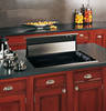
.... Hood raises over cooktop surface and retracts when not in use. • 500 CFM - GE Profile™ 30" Telescopic Downdraft System Features and Benefits • Telescopic downdraft hood - OFF LEFT LO • Removable grease filter - Stainless steel JVB94SHSS Specification Revised 5/09 220963 JVB94SH - Durable filters can be removed for easy cleaning and...
.... Hood raises over cooktop surface and retracts when not in use. • 500 CFM - GE Profile™ 30" Telescopic Downdraft System Features and Benefits • Telescopic downdraft hood - OFF LEFT LO • Removable grease filter - Stainless steel JVB94SHSS Specification Revised 5/09 220963 JVB94SH - Durable filters can be removed for easy cleaning and...