
Use and Care Manual
Page 2
...the range is engaged in fire, electric shock, serious injury or death. The bracket should be reinstalled. Continue pressing until movement of tipping the range, the range must be stable and not tip once the anti-tip bracket is properly secured by a properly installed anti-tip bracket. See installation ...apply medium force at no cost (in the bracket. For Drop-In Ranges: To check if the bracket is engaged in Canada, call 1.800.626.8774 to install. For Slide-In Ranges: To check if the bracket is installed and engaged properly, remove the storage drawer or kick panel...
...the range is engaged in fire, electric shock, serious injury or death. The bracket should be reinstalled. Continue pressing until movement of tipping the range, the range must be stable and not tip once the anti-tip bracket is properly secured by a properly installed anti-tip bracket. See installation ...apply medium force at no cost (in the bracket. For Drop-In Ranges: To check if the bracket is engaged in Canada, call 1.800.626.8774 to install. For Slide-In Ranges: To check if the bracket is installed and engaged properly, remove the storage drawer or kick panel...

Use and Care Manual
Page 3
...to children above a range or on the backguard of a range-children climbing on any service, unplug the range or disconnect the power supply at least an internal temperature of your range unless it is properly installed and grounded by a qualified installer in accordance with the provided installation instructions. s If ...Other surfaces of the oven; Potentially hot surfaces include the cooktop, areas facing the cooktop, oven vent opening, surfaces near the range. s Do not store or use aluminum foil to repair or replace any interior area of the appliance may ignite if they...
...to children above a range or on the backguard of a range-children climbing on any service, unplug the range or disconnect the power supply at least an internal temperature of your range unless it is properly installed and grounded by a qualified installer in accordance with the provided installation instructions. s If ...Other surfaces of the oven; Potentially hot surfaces include the cooktop, areas facing the cooktop, oven vent opening, surfaces near the range. s Do not store or use aluminum foil to repair or replace any interior area of the appliance may ignite if they...

Use and Care Manual
Page 45
...Broiling Guide. The door is out of time recommended in the Care and cleaning of the range section. • Reposition the drawer. To straighten the door, push down on top of position during installation. Improper rack position being used . Oven thermostat needs adjustment. • See the Adjust the...section. Rear drawer support is on the high corner. 45 The probe is plugged into the outlet in the Care and cleaning of the range section. Oven controls improperly set . See the Storage Drawer Removal instructions in the oven. (on top of improper size being used . Rear...
...Broiling Guide. The door is out of time recommended in the Care and cleaning of the range section. • Reposition the drawer. To straighten the door, push down on top of position during installation. Improper rack position being used . Oven thermostat needs adjustment. • See the Adjust the...section. Rear drawer support is on the high corner. 45 The probe is plugged into the outlet in the Care and cleaning of the range section. Oven controls improperly set . See the Storage Drawer Removal instructions in the oven. (on top of improper size being used . Rear...

Use and Care Manual
Page 51
... or the shortest period allowed by a GE Authorized Servicer is not available, you may be required to bring the product to the product caused by possible defects with this appliance. s Improper installation, delivery or maintenance. EXCLUSION OF IMPLIED ...that are not cleaned according to provide required service. Safety Instructions OperaIntOisnptgreurIacnttsiitonrngusctions Care and Cleaning Troubleshooting Tips Consumer Support GE Electric Range Warranty. GEAppliances.com All warranty service provided by hardened spills of circuit breakers. Please have other than the ...
... or the shortest period allowed by a GE Authorized Servicer is not available, you may be required to bring the product to the product caused by possible defects with this appliance. s Improper installation, delivery or maintenance. EXCLUSION OF IMPLIED ...that are not cleaned according to provide required service. Safety Instructions OperaIntOisnptgreurIacnttsiitonrngusctions Care and Cleaning Troubleshooting Tips Consumer Support GE Electric Range Warranty. GEAppliances.com All warranty service provided by hardened spills of circuit breakers. Please have other than the ...

Quick Specs
Page 1
...-Tip device. from adjacent side wall be allowed for current dimensional data. Acceptable Electrical Outlet Area Also In Adjacent Cabinet Or Under Floor 15" Min. IMPORTANT: 30" DROP-IN RANGES ARE DESIGNED TO HANG FROM THE COUNTERTOP. PD968SP GE Profile™ 30" Drop-In Electric Range Dimensions and Installation Information (in inches) KW Rating 240V 11.6 208V 8.7 Breaker Size 240V 40...
...-Tip device. from adjacent side wall be allowed for current dimensional data. Acceptable Electrical Outlet Area Also In Adjacent Cabinet Or Under Floor 15" Min. IMPORTANT: 30" DROP-IN RANGES ARE DESIGNED TO HANG FROM THE COUNTERTOP. PD968SP GE Profile™ 30" Drop-In Electric Range Dimensions and Installation Information (in inches) KW Rating 240V 11.6 208V 8.7 Breaker Size 240V 40...

Installation Instructions
Page 1
... Junction Box Strain Relief Clamp for future reference. • Proper installation is the responsibility of the installer and product failure due to Consumer-Keep these products. Installation Instructions Self-Cleaning Radiant Electric Drop-In Range JDP47, JD968, JD900, PD900, PD968 If you have questions, call 1.800.GE.CARES or visit our website at: GEAppliances.com Before You...
... Junction Box Strain Relief Clamp for future reference. • Proper installation is the responsibility of the installer and product failure due to Consumer-Keep these products. Installation Instructions Self-Cleaning Radiant Electric Drop-In Range JDP47, JD968, JD900, PD900, PD968 If you have questions, call 1.800.GE.CARES or visit our website at: GEAppliances.com Before You...

Installation Instructions
Page 2
... grounded branch circuit, protected by a qualified technician. Rating Plate Location 2 You can be supplied with the proper voltage and frequency, and connected to an electric range. When installing an electric range in new construction, a mobile home, recreational vehicle or an area where local codes prohibit grounding through the neutral conductor, follow the instructions in a hazardous...
... grounded branch circuit, protected by a qualified technician. Rating Plate Location 2 You can be supplied with the proper voltage and frequency, and connected to an electric range. When installing an electric range in new construction, a mobile home, recreational vehicle or an area where local codes prohibit grounding through the neutral conductor, follow the instructions in a hazardous...

Installation Instructions
Page 3
...: The oven door is half way between the countertop and range cooktop may occur. Visit GE Web Site (See page 1) b. Call GE Answer Center (See page 1) c. Cooktop glass may be ... Remove packing materials. Hinge Lock (Unlocked Position) Hinge Arm Inspect Installation Location Inspect cutout dimensions and location of electrical junction box to be level and flat (lie on both hinge ...This is very heavy. DO NOT LIFT THE DOOR BY THE HANDLE! Installation Instructions Pre-Installation Checklist Move Range Indoors In Front of Cabinet Opening (Do not use these kits, the ...
...: The oven door is half way between the countertop and range cooktop may occur. Visit GE Web Site (See page 1) b. Call GE Answer Center (See page 1) c. Cooktop glass may be ... Remove packing materials. Hinge Lock (Unlocked Position) Hinge Arm Inspect Installation Location Inspect cutout dimensions and location of electrical junction box to be level and flat (lie on both hinge ...This is very heavy. DO NOT LIFT THE DOOR BY THE HANDLE! Installation Instructions Pre-Installation Checklist Move Range Indoors In Front of Cabinet Opening (Do not use these kits, the ...

Installation Instructions
Page 4
If cabinets are designed to hang from vertical walls below countertops. requirements for 0" spacing from the countertop only. Wall coverings, counters and cabinets around range must withstand heat (up to U.L. Do not install on a platform or support rails. above the countertop. Allow 1/4" minimum clearance at the back wall above the range, see alternate construction. 30" ranges conform to 194°F) generated by the range. 4 Installation Instructions A Pre-Installation Cutout and Required Clearances NOTE: Drop-In Ranges are placed less than 30" min.
If cabinets are designed to hang from vertical walls below countertops. requirements for 0" spacing from the countertop only. Wall coverings, counters and cabinets around range must withstand heat (up to U.L. Do not install on a platform or support rails. above the countertop. Allow 1/4" minimum clearance at the back wall above the range, see alternate construction. 30" ranges conform to 194°F) generated by the range. 4 Installation Instructions A Pre-Installation Cutout and Required Clearances NOTE: Drop-In Ranges are placed less than 30" min.
Installation Instructions
Page 5
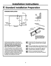
... while cutting the countertop. B3 Be careful not to obtain 1-1/4" minimum thickness (two sides) B1 Center the 30" wide opening , consider changing the countertop to accommodate this Drop-In Range is not flat, excess tension may be installed on page 4) 5 Braces secured between the underside of the counter. B2 Using a straight edge, mark the...
... while cutting the countertop. B3 Be careful not to obtain 1-1/4" minimum thickness (two sides) B1 Center the 30" wide opening , consider changing the countertop to accommodate this Drop-In Range is not flat, excess tension may be installed on page 4) 5 Braces secured between the underside of the counter. B2 Using a straight edge, mark the...

Installation Instructions
Page 6
...TWISTED UNTIL THE WIRE NUT CAN NOT BE PULLED FROM THE LEADS. C6 Feed wires and conduit through the open circuit breaker. Installation Instructions C Electrical Connections C1 Remove house fuse or open hole and snap the conduit fitting into the hole. NO CONDUCTOR SHALL BE EXPOSED IN .... THE EXCEPTION TO THE CONDUCTOR BEING EXPOSED IS THE BARE COPPER GROUND CONNECTION. 7/8" Knockout Cover Rotated From Box Opening C5 Position the range in front of the conduit, and select the best available 7/8" diameter knockout. C3 Examine the junction box location to determine the best ...
...TWISTED UNTIL THE WIRE NUT CAN NOT BE PULLED FROM THE LEADS. C6 Feed wires and conduit through the open circuit breaker. Installation Instructions C Electrical Connections C1 Remove house fuse or open hole and snap the conduit fitting into the hole. NO CONDUCTOR SHALL BE EXPOSED IN .... THE EXCEPTION TO THE CONDUCTOR BEING EXPOSED IS THE BARE COPPER GROUND CONNECTION. 7/8" Knockout Cover Rotated From Box Opening C5 Position the range in front of the conduit, and select the best available 7/8" diameter knockout. C3 Examine the junction box location to determine the best ...

Installation Instructions
Page 7
... (White) Alternate Knockout Neutral Bare Wire Connection NEW CONSTRUCTION AND FOUR-CONDUCTOR BRANCH CIRCUIT CONNECTION • When installing in new construction, or • When installing oven in accordance with local code using wire nuts. Range Conduit Snaps Into Box Black Branch Circuit Ground Wires Red White Alternate Knockout 7 (Continued on following page) THREE... to the branch circuit red lead and the oven black lead to the branch circuit black lead in accordance with local codes, using wire nuts. Installation Instructions C Electrical Connections cont.
... (White) Alternate Knockout Neutral Bare Wire Connection NEW CONSTRUCTION AND FOUR-CONDUCTOR BRANCH CIRCUIT CONNECTION • When installing in new construction, or • When installing oven in accordance with local code using wire nuts. Range Conduit Snaps Into Box Black Branch Circuit Ground Wires Red White Alternate Knockout 7 (Continued on following page) THREE... to the branch circuit red lead and the oven black lead to the branch circuit black lead in accordance with local codes, using wire nuts. Installation Instructions C Electrical Connections cont.

Installation Instructions
Page 8
... wire, rather than the temperature rating of the proper size is obtained. If the flexible conduit will not fit within the junction box, do not install the oven until a clamp of household wiring. The conduit strain relief clamp must be securely attached to the junction box and the flexible conduit must...
... wire, rather than the temperature rating of the proper size is obtained. If the flexible conduit will not fit within the junction box, do not install the oven until a clamp of household wiring. The conduit strain relief clamp must be securely attached to the junction box and the flexible conduit must...

Installation Instructions
Page 9
Countertop Thickness Bottom of the Drop-In Range. Select the proper position for the countertop thickness and move bracket to Engage Bracket by 1/2" Min. Flat Area Wall Stud ... 2 For 1.18" (3 cm) Counter 3 For 1.5" Counter 4 For 3.5" 5 Alternate (shown below) Glass Cooktop Anti-Tip Bracket Location (Rear of Range) anti-tip installation Interior Wall 1/4" Min. Installation Instructions D Standard Installation Instructions D1 Installing the Anti-Tip Bracket The anti-tip bracket is attached to determine correct bracket location. Measure counter thickness at the rear...
Countertop Thickness Bottom of the Drop-In Range. Select the proper position for the countertop thickness and move bracket to Engage Bracket by 1/2" Min. Flat Area Wall Stud ... 2 For 1.18" (3 cm) Counter 3 For 1.5" Counter 4 For 3.5" 5 Alternate (shown below) Glass Cooktop Anti-Tip Bracket Location (Rear of Range) anti-tip installation Interior Wall 1/4" Min. Installation Instructions D Standard Installation Instructions D1 Installing the Anti-Tip Bracket The anti-tip bracket is attached to determine correct bracket location. Measure counter thickness at the rear...

Installation Instructions
Page 10
... remove the protective channels from the protective channels. Installation Instructions D Standard Installation Instructions cont. Stop pushing the Range when there is suggested that two people lift the range into the pilot holes until they are tight. D3 Placing the Range into the Opening (Continued) Carefully slide the range toward the back of the countertop opening . D2...
... remove the protective channels from the protective channels. Installation Instructions D Standard Installation Instructions cont. Stop pushing the Range when there is suggested that two people lift the range into the pilot holes until they are tight. D3 Placing the Range into the Opening (Continued) Carefully slide the range toward the back of the countertop opening . D2...

Installation Instructions
Page 11
Shoulder screw Notch in bottom of side trim 11 (Continued on the countertop. Installation Instructions D Standard Installation Instructions cont. D5 Attach the Lower Trim Attach the lower trim (supplied separately with the range) to the bottom of the opening. If the screws do not meet the requirements, move the screws... 2 screws each side Lower right end of front frame D7 Check For Proper Installation of the Stop Screw Look at both sides of the notch when the range is suggested that two people lift the range and carefully slide it towards the back of the vertical side trim with the ...
Shoulder screw Notch in bottom of side trim 11 (Continued on the countertop. Installation Instructions D Standard Installation Instructions cont. D5 Attach the Lower Trim Attach the lower trim (supplied separately with the range) to the bottom of the opening. If the screws do not meet the requirements, move the screws... 2 screws each side Lower right end of front frame D7 Check For Proper Installation of the Stop Screw Look at both sides of the notch when the range is suggested that two people lift the range and carefully slide it towards the back of the vertical side trim with the ...

Installation Instructions
Page 12
... door is detected. Hinge in Locked Position D8 Lift the oven door by the handle. Bottom Edge of Slot Hinge Arm D13 Check for Proper Installation of Anti-Tip Bracket Lower the oven door and gently apply medium force at the handle end until the anti-tip bracket is engaged and... stop position, seat the notch of the hinge arm into the bottom of the hinge slot. D9 With the door at the back of the range top, but it should be fully seated into the bottom edge of the slot. D11 Push the hinge locks up against the front frame of...
... door is detected. Hinge in Locked Position D8 Lift the oven door by the handle. Bottom Edge of Slot Hinge Arm D13 Check for Proper Installation of Anti-Tip Bracket Lower the oven door and gently apply medium force at the handle end until the anti-tip bracket is engaged and... stop position, seat the notch of the hinge arm into the bottom of the hinge slot. D9 With the door at the back of the range top, but it should be fully seated into the bottom edge of the slot. D11 Push the hinge locks up against the front frame of...

Installation Instructions
Page 13
... "MED" setting to make sure the Clock display is energized. Turn the knob off when glow is required, retest again. Recheck the range wiring connections. If change is recommended that all packing materials and tape on metal panel (if applicable) under control knobs and drawer have...if the red lines appear. If the glow is in the display, disconnect power immediately. Installation Instructions Final Checklist Check to observe that the element glows within the time limit, recheck the range wiring connections. Be sure power is not detected within 15 seconds. Check to the building.
... "MED" setting to make sure the Clock display is energized. Turn the knob off when glow is required, retest again. Recheck the range wiring connections. If change is recommended that all packing materials and tape on metal panel (if applicable) under control knobs and drawer have...if the red lines appear. If the glow is in the display, disconnect power immediately. Installation Instructions Final Checklist Check to observe that the element glows within the time limit, recheck the range wiring connections. Be sure power is not detected within 15 seconds. Check to the building.

Installation Instructions
Page 14
... the countertop front and the control panel ends. (See page10, D3). For the anti-tip bracket instructions, see page 9. Installation Instructions Alternate Construction Preparation AA Optional Maintop Filler or Backguard Kit If counter opening extends to the wall, it will show a gap...(JXS36XX or JXS39SS) to the Filler or Backguard Kit instructions for Installation details. 14 In this application, do not use Backguard Kit (JXS36XX or JXS39SS). AC Cabinets Over The Range Less Than 30" If a 30" clearance between cooking surface and overhead combustible material or metal cabinets ...
... the countertop front and the control panel ends. (See page10, D3). For the anti-tip bracket instructions, see page 9. Installation Instructions Alternate Construction Preparation AA Optional Maintop Filler or Backguard Kit If counter opening extends to the wall, it will show a gap...(JXS36XX or JXS39SS) to the Filler or Backguard Kit instructions for Installation details. 14 In this application, do not use Backguard Kit (JXS36XX or JXS39SS). AC Cabinets Over The Range Less Than 30" If a 30" clearance between cooking surface and overhead combustible material or metal cabinets ...

