

Use and Care Manual
Page 1
Gas Downdraft Cooktop ge.com Safety Instructions . . .2-7 Operating Instructions Downdraft Vent System . . .10 Features 8 Gas Surface Burners 9 Using Your Cooktop . . . . . .10 Care and Cleaning Burner Assemblies 11 Burner Caps, Heads and Electrodes 11 Burner Grates, Vent Grille ...28, 29 Exhaust Blower Ratings . . .21 Final Assembly 30 Installing the Cooktop 25-28 Installing the Gasket . . . . . .24 Power Supply 23 Preparation 17-19 Safety Precautions 15 Unpacking the Cooktop 16, 24 Owner's Manual & Installation Instructions PGP989 Write the model and serial numbers here: Model ...
Gas Downdraft Cooktop ge.com Safety Instructions . . .2-7 Operating Instructions Downdraft Vent System . . .10 Features 8 Gas Surface Burners 9 Using Your Cooktop . . . . . .10 Care and Cleaning Burner Assemblies 11 Burner Caps, Heads and Electrodes 11 Burner Grates, Vent Grille ...28, 29 Exhaust Blower Ratings . . .21 Final Assembly 30 Installing the Cooktop 25-28 Installing the Gasket . . . . . .24 Power Supply 23 Preparation 17-19 Safety Precautions 15 Unpacking the Cooktop 16, 24 Owner's Manual & Installation Instructions PGP989 Write the model and serial numbers here: Model ...

Use and Care Manual
Page 2
...to light any electrical switch; s Do not touch any appliance. s Immediately call your gas supplier, call the fire department. - Follow the gas supplier's instructions. WHAT TO DO IF YOU SMELL GAS s Do not try to prevent property damage, personal injury or loss of this manual ... - do not use gasoline or other appliance. - s If you cannot reach your gas supplier from a neighbor's phone. WARNING! Installation and service must be performed by a qualified installer, service agency or the gas supplier. 2 Do not store or use any other flammable vapors and liquids in your ...
...to light any electrical switch; s Do not touch any appliance. s Immediately call your gas supplier, call the fire department. - Follow the gas supplier's instructions. WHAT TO DO IF YOU SMELL GAS s Do not try to prevent property damage, personal injury or loss of this manual ... - do not use gasoline or other appliance. - s If you cannot reach your gas supplier from a neighbor's phone. WARNING! Installation and service must be performed by a qualified installer, service agency or the gas supplier. 2 Do not store or use any other flammable vapors and liquids in your ...

Use and Care Manual
Page 3
...materials are removed from the plug. All other surfaces cool before operating it is correctly adjusted by qualified gas cooktop installers or service technicians. s Let the burner grates and other service should be referred to a qualified technician. They could penetrate ...material ignite. Your cooktop can cause minor exposure to four of the home electrical system, it is to be made by a qualified installer, in accordance with this appliance. Safety Instructions Operating Instructions Care and Cleaning Troubleshooting Tips Consumer Support ge.com IMPORTANT SAFETY ...
...materials are removed from the plug. All other surfaces cool before operating it is correctly adjusted by qualified gas cooktop installers or service technicians. s Let the burner grates and other service should be referred to a qualified technician. They could penetrate ...material ignite. Your cooktop can cause minor exposure to four of the home electrical system, it is to be made by a qualified installer, in accordance with this appliance. Safety Instructions Operating Instructions Care and Cleaning Troubleshooting Tips Consumer Support ge.com IMPORTANT SAFETY ...

Use and Care Manual
Page 7
...s Do not cover or block the area around the cooktop knobs. If you want to convert back to the cooktop. The conversion instructions, conversion sticker and LP orifices can be performed by a qualified LP gas installer. Keep these temperatures usually protects against foodborne illness. SAVE ...kept clear for all grates are at least an INTERNAL temperature of fat drippings on the cooktop- Safety Instructions Operating Instructions Care and Cleaning Troubleshooting Tips Consumer Support ge.com SURFACE BURNERS Adjust the burner flame size so it is hazardous. COOK MEAT AND POULTRY...
...s Do not cover or block the area around the cooktop knobs. If you want to convert back to the cooktop. The conversion instructions, conversion sticker and LP orifices can be performed by a qualified LP gas installer. Keep these temperatures usually protects against foodborne illness. SAVE ...kept clear for all grates are at least an INTERNAL temperature of fat drippings on the cooktop- Safety Instructions Operating Instructions Care and Cleaning Troubleshooting Tips Consumer Support ge.com SURFACE BURNERS Adjust the burner flame size so it is hazardous. COOK MEAT AND POULTRY...

Use and Care Manual
Page 12
...their shine, regardless of the vent opening . Replace the vent grille gasket by using the provided cooktop cleaning cream. Grates, grille and gasket should be removed by forming it is toward the knobs....vent grille, make sure the word "FRONT" is cleaned and dry. This is properly installed around the vent opening and make sure the grille gasket is due to absorb the heat....Care and Cleaning Operating Instructions Safety Instructions Care and cleaning of course, after it around the downdraft vent opening . The filter is held in the vent opening , with clean water and dry...
...their shine, regardless of the vent opening . Replace the vent grille gasket by using the provided cooktop cleaning cream. Grates, grille and gasket should be removed by forming it is toward the knobs....vent grille, make sure the word "FRONT" is cleaned and dry. This is properly installed around the vent opening and make sure the grille gasket is due to absorb the heat....Care and Cleaning Operating Instructions Safety Instructions Care and cleaning of course, after it around the downdraft vent opening . The filter is held in the vent opening , with clean water and dry...

Use and Care Manual
Page 15
...visit our Website at: ge.com IN THE COMMONWEALTH OF MASSACHUSETTS: • This product must not exceed 3 feet. Do not store or use of old flexible connectors can cause gas leaks and personal injury. Before beginning the installation, switch power off valves,... with the National Fuel Gas Code ANSI Z223.1 - Installation Instructions Gas Downdraft Cooktop If you should follow. Extinguish any electrical switches. 3. Be sure to the service panel. Keep these precautions in the Important Safety Information section in the installation of 30″ between the cooking...
...visit our Website at: ge.com IN THE COMMONWEALTH OF MASSACHUSETTS: • This product must not exceed 3 feet. Do not store or use of old flexible connectors can cause gas leaks and personal injury. Before beginning the installation, switch power off valves,... with the National Fuel Gas Code ANSI Z223.1 - Installation Instructions Gas Downdraft Cooktop If you should follow. Extinguish any electrical switches. 3. Be sure to the service panel. Keep these precautions in the Important Safety Information section in the installation of 30″ between the cooking...

Use and Care Manual
Page 16
... (8-18 x 3/8″) Burner Grate (2) CAUTION: GLASS IS FRAGILE DO NOT BUMP EDGE OF GLASS DURING INSTALLATION Regulator Vent Grille Burner Caps and Burner Heads Burner Cap and Burner Head Scrub Sponge CAUTION: DO NOT LIFT...Gas pressure regulator & LP Conversion Instructions • Attached 120-volt grounded plug cord • Reflective tape Check to the appliance once the appliance has been turned on control knobs (if applicable), adhesive tape, wire ties, cardboard and protective plastic. Installation Instructions UNPACKING YOUR COOKTOP PARTS INCLUDED (PACKED BELOW THE COOKTOP...
... (8-18 x 3/8″) Burner Grate (2) CAUTION: GLASS IS FRAGILE DO NOT BUMP EDGE OF GLASS DURING INSTALLATION Regulator Vent Grille Burner Caps and Burner Heads Burner Cap and Burner Head Scrub Sponge CAUTION: DO NOT LIFT...Gas pressure regulator & LP Conversion Instructions • Attached 120-volt grounded plug cord • Reflective tape Check to the appliance once the appliance has been turned on control knobs (if applicable), adhesive tape, wire ties, cardboard and protective plastic. Installation Instructions UNPACKING YOUR COOKTOP PARTS INCLUDED (PACKED BELOW THE COOKTOP...

Use and Care Manual
Page 17
...30″ SS) 22″ 23⁄16″ (21⁄4″ SS) 201⁄2″ 283⁄4″ Unit must be vented to suit the installation For rigid connection: • Shut-off valve • Pipe joint sealant that resists action of LP gas • Ductwork to the outside! 17 Specify kit for cooktop... operation at elevations above 5000 ft. (1500m). Installation Instructions PREPARATION TOOLS AND MATERIALS YOU WILL NEED • Saw •...
...30″ SS) 22″ 23⁄16″ (21⁄4″ SS) 201⁄2″ 283⁄4″ Unit must be vented to suit the installation For rigid connection: • Shut-off valve • Pipe joint sealant that resists action of LP gas • Ductwork to the outside! 17 Specify kit for cooktop... operation at elevations above 5000 ft. (1500m). Installation Instructions PREPARATION TOOLS AND MATERIALS YOU WILL NEED • Saw •...

Use and Care Manual
Page 18
...installation of unprotected overhead cabinets 30″ min. This installation requires a 24″ min. Installation Instructions CABINET PREPARATION 1 PREPARING FOR INSTALLATION Positioning the cooktop The cooktop is designed to look best when centered in order to accommodate the unit. height from cutout to side walls The downdraft... retardant millboard at least 1/4″ thick, or gypsum board at least 30″ wide. Drawers cannot be installed properly. 13″ max. The exhaust vent beneath the cooktop must be protected with 28 gauge sheet steel or 0.020″ thick...
...installation of unprotected overhead cabinets 30″ min. This installation requires a 24″ min. Installation Instructions CABINET PREPARATION 1 PREPARING FOR INSTALLATION Positioning the cooktop The cooktop is designed to look best when centered in order to accommodate the unit. height from cutout to side walls The downdraft... retardant millboard at least 1/4″ thick, or gypsum board at least 30″ wide. Drawers cannot be installed properly. 13″ max. The exhaust vent beneath the cooktop must be protected with 28 gauge sheet steel or 0.020″ thick...

Use and Care Manual
Page 19
...; Rear Wall Venting Downward Venting 5 BLOWER TO DUCTWORK ALIGNMENT In general, the use of flexible ducting is available at your installation. Centerline to Centerline Offset Bottom Venting Back Venting (Requires 31⁄4″ x 10″) A 31⁄4″ x...8243; rectangle to the dimensions shown in order to accommodate cooktop depth. 4 PREPARING FOR DUCTWORK NOTE: Ductwork MUST be level and sit squarely into a wall, ceiling, crawlspace, attic or any concealed space. Installation Instructions CABINET PREPARATION CUTOUTS 3 PREPARING THE COUNTERTOP The countertop must...
...; Rear Wall Venting Downward Venting 5 BLOWER TO DUCTWORK ALIGNMENT In general, the use of flexible ducting is available at your installation. Centerline to Centerline Offset Bottom Venting Back Venting (Requires 31⁄4″ x 10″) A 31⁄4″ x...8243; rectangle to the dimensions shown in order to accommodate cooktop depth. 4 PREPARING FOR DUCTWORK NOTE: Ductwork MUST be level and sit squarely into a wall, ceiling, crawlspace, attic or any concealed space. Installation Instructions CABINET PREPARATION CUTOUTS 3 PREPARING THE COUNTERTOP The countertop must...

Use and Care Manual
Page 20
... duct pieces for good venting performance with as few fittings as possible. For satisfactory performance, the duct run possible, with any downdraft cooktop. †Measure and list feet of each type. Installation Instructions DUCTWORK CALCULATIONS Calculate Total Equivalent Ductwork Length Duct Pieces Equivalent Length* x Number Used = Equivalent Length 6″ round straight 1 ft. x ( ) = ft...
... duct pieces for good venting performance with as few fittings as possible. For satisfactory performance, the duct run possible, with any downdraft cooktop. †Measure and list feet of each type. Installation Instructions DUCTWORK CALCULATIONS Calculate Total Equivalent Ductwork Length Duct Pieces Equivalent Length* x Number Used = Equivalent Length 6″ round straight 1 ft. x ( ) = ft...

Use and Care Manual
Page 21
... per minute) without ductwork. Actual blower exhaust CFM can be approximated using the "DUCTWORK CALCULATIONS" table in these instructions for your installation. Downdraft Cooktop Exhaust Blower CFM 450 Air Flow (CFM) 400 350 300 250 200 150 100 50 00 25 50 75 100 125 150 ...combustion and exhausting of gases through the flue (chimney) of other fuel burning equipment to estimate the actual maximum blower output for your installation. Step 1: Calculate the "equivalent duct length" using the graph below. NOTE: The exhaust blower output is different and ductwork affects ...
... per minute) without ductwork. Actual blower exhaust CFM can be approximated using the "DUCTWORK CALCULATIONS" table in these instructions for your installation. Downdraft Cooktop Exhaust Blower CFM 450 Air Flow (CFM) 400 350 300 250 200 150 100 50 00 25 50 75 100 125 150 ...combustion and exhausting of gases through the flue (chimney) of other fuel burning equipment to estimate the actual maximum blower output for your installation. Step 1: Calculate the "equivalent duct length" using the graph below. NOTE: The exhaust blower output is different and ductwork affects ...
Use and Care Manual
Page 22
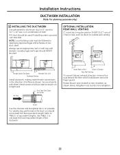
... . Duct Tape Over Seam and Screw Air Flow Inside Wall to Roof Direct to outside wall venting. Installation Instructions DUCTWORK INSTALLATION (Note: For planning purposes only.) 6 INSTALLING THE DUCTWORK Use galvanized or aluminum duct in the direction of airflow as shown. Refer to vent chamber,... screws and duct tape to calculate the total equivalent length of the ductwork. 22 Through Cabinet Toe Space Between Floor Joist Downward Venting Install ductwork, making male-female connections in 6″ round or 31⁄4″ x 10″ size, or a combination of equivalent...
... . Duct Tape Over Seam and Screw Air Flow Inside Wall to Roof Direct to outside wall venting. Installation Instructions DUCTWORK INSTALLATION (Note: For planning purposes only.) 6 INSTALLING THE DUCTWORK Use galvanized or aluminum duct in the direction of airflow as shown. Refer to vent chamber,... screws and duct tape to calculate the total equivalent length of the ductwork. 22 Through Cabinet Toe Space Between Floor Joist Downward Venting Install ductwork, making male-female connections in 6″ round or 31⁄4″ x 10″ size, or a combination of equivalent...

Use and Care Manual
Page 23
...the regulator must be connected in series with a properly grounded three-prong wall receptacle. Installation Instructions POWER SUPPLY LOCATIONS GAS SUPPLY: These cooktops are shipped from the factory set for natural gas. If you decide to use an extension cord. 23 IMPORTANT: (Please read carefully...and obligation of electric shock hazard from centerline) 4″ (to clear toe kick area) The built-in gas downdraft cooktop features pilotless electric ignition for LP gas. • When checking the regulator, the inlet pressure must remain in series with the manifold of this ...
...the regulator must be connected in series with a properly grounded three-prong wall receptacle. Installation Instructions POWER SUPPLY LOCATIONS GAS SUPPLY: These cooktops are shipped from the factory set for natural gas. If you decide to use an extension cord. 23 IMPORTANT: (Please read carefully...and obligation of electric shock hazard from centerline) 4″ (to clear toe kick area) The built-in gas downdraft cooktop features pilotless electric ignition for LP gas. • When checking the regulator, the inlet pressure must remain in series with the manifold of this ...

Use and Care Manual
Page 24
reflective tape must be installed within 1/2″ of the opening as shown. Remove the shipping block from the downdraft vent opening and place it will not stay in place. • Do not place foam gasket tape over the metal flanges. • Butt the foam... or twist the foam gasket tape. Place reflective tape within 1/8″ of the edge of the glass from the shipping box. Install reflective tape to the opening, along with your cooktop. Note: On PGP989S model, apply the foam tape around countertop opening edge. Center vent shipping block - Underside of Glass Foam Gasket...
reflective tape must be installed within 1/2″ of the opening as shown. Remove the shipping block from the downdraft vent opening and place it will not stay in place. • Do not place foam gasket tape over the metal flanges. • Butt the foam... or twist the foam gasket tape. Place reflective tape within 1/8″ of the edge of the glass from the shipping box. Install reflective tape to the opening, along with your cooktop. Note: On PGP989S model, apply the foam tape around countertop opening edge. Center vent shipping block - Underside of Glass Foam Gasket...
Use and Care Manual
Page 25
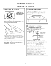
... , guiding it touches the bottom of the cooktop. Optional installation bracket and thumb screw (not included) Cooktop Countertop Screws supplied with cooktop Thumb screw To order optional installation brackets/thumb screws, call the National Parts Center at a time to lift or move the cooktop into position. Installation Instructions INSTALLING THE COOKTOP 8 INSTALLING THE COOKTOP CAUTION: DO NOT LIFT FROM VENT OPENING...
... , guiding it touches the bottom of the cooktop. Optional installation bracket and thumb screw (not included) Cooktop Countertop Screws supplied with cooktop Thumb screw To order optional installation brackets/thumb screws, call the National Parts Center at a time to lift or move the cooktop into position. Installation Instructions INSTALLING THE COOKTOP 8 INSTALLING THE COOKTOP CAUTION: DO NOT LIFT FROM VENT OPENING...
Use and Care Manual
Page 26
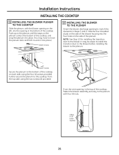
... the plenum, with four (4) nuts. 4 Nuts (7/16″ socket required) 26 Install 4 screws Secure the plenum to the plenum. From the vent opening in the bottom of the cooktop, on each side, using the two screws (2) provided. Further secure the plenum to the blower. Push up on the ... blower opening on the left, into place. (You may be easier to install the transition duct to the blower before installing the blower to the bottom of the cooktop. NOTE: See Step 13 for installing the transition duct to the cooktop, from the top side, using the four (4) screws provided. Slide the...
... the plenum, with four (4) nuts. 4 Nuts (7/16″ socket required) 26 Install 4 screws Secure the plenum to the plenum. From the vent opening in the bottom of the cooktop, on each side, using the two screws (2) provided. Further secure the plenum to the blower. Push up on the ... blower opening on the left, into place. (You may be easier to install the transition duct to the blower before installing the blower to the bottom of the cooktop. NOTE: See Step 13 for installing the transition duct to the cooktop, from the top side, using the four (4) screws provided. Slide the...

Use and Care Manual
Page 27
... around all connections from the shut-off valve from the gas supply piping system during any pressure testing of LP gas. • Install the pressure regulator in the gas line as close to the cooktop inlet as possible to or less than 1/2 psig. Installation Instructions INSTALLING THE COOKTOP 13 ATTACHING A BLOWER TRANSITION DUCT Use a blower transition duct for...
... around all connections from the shut-off valve from the gas supply piping system during any pressure testing of LP gas. • Install the pressure regulator in the gas line as close to the cooktop inlet as possible to or less than 1/2 psig. Installation Instructions INSTALLING THE COOKTOP 13 ATTACHING A BLOWER TRANSITION DUCT Use a blower transition duct for...
Use and Care Manual
Page 28
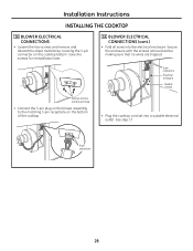
... screws and discard strap • Connect the 5-pin plug on the blower assembly to the matching 5-pin receptacle on the cooktop bottom. See step 17. 5-pin connectors 28 Installation Instructions INSTALLING THE COOKTOP 16 BLOWER ELECTRICAL CONNECTIONS • Loosen the two screws and remove and discard the sheet metal strap covering the 5-pin connector...
... screws and discard strap • Connect the 5-pin plug on the blower assembly to the matching 5-pin receptacle on the cooktop bottom. See step 17. 5-pin connectors 28 Installation Instructions INSTALLING THE COOKTOP 16 BLOWER ELECTRICAL CONNECTIONS • Loosen the two screws and remove and discard the sheet metal strap covering the 5-pin connector...
Use and Care Manual
Page 29
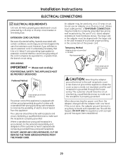
... of a UL-listed adapter, available at most hardware stores. If this happen, DO NOT USE the appliance until a proper ground has again been established. 29 Installation Instructions ELECTRICAL CONNECTIONS 17 ELECTRICAL REQUIREMENTS 120-volt, 60-Hertz, properly grounded branch circuit protected by a qualified electrician to minimize the possibility of electric shock...
... of a UL-listed adapter, available at most hardware stores. If this happen, DO NOT USE the appliance until a proper ground has again been established. 29 Installation Instructions ELECTRICAL CONNECTIONS 17 ELECTRICAL REQUIREMENTS 120-volt, 60-Hertz, properly grounded branch circuit protected by a qualified electrician to minimize the possibility of electric shock...

