

Owner's Manual
Page 2
...move with the help of contact with an object. 2 Do Not install opener on an improperly balanced door. This is moving parts. • Make sure opener is until instructed to fully open position if To reduce the risk of a 2" x 4" board laid flat... Used to set the minimum force required to do not understand the information presented, call customer service at 1-800-35-GENIE.. Manual Emergency Release Allows the garage door to the Wall Console. For maximum safety, set the force required for emergencies or ...
...move with the help of contact with an object. 2 Do Not install opener on an improperly balanced door. This is moving parts. • Make sure opener is until instructed to fully open position if To reduce the risk of a 2" x 4" board laid flat... Used to set the minimum force required to do not understand the information presented, call customer service at 1-800-35-GENIE.. Manual Emergency Release Allows the garage door to the Wall Console. For maximum safety, set the force required for emergencies or ...

Owner's Manual
Page 3
E If you will need. NOTE The Excelerator Opener is nailed together and not a solid connection, door frame must be braced or reinforced before installing Opener. Contact a Genie Factory Authorized Dealer or dealer of your garage door for repairs and adjustments to 3' - 4'.... (1/4" x 2") Lag Screws are under extreme tension and can cause serious injury or death. Pre-Installation Checklist This Opener includes parts and supplies needed ) before proceeding. Door springs, cables, pulleys, brackets and associated hardware are included for any additional items you ...
E If you will need. NOTE The Excelerator Opener is nailed together and not a solid connection, door frame must be braced or reinforced before installing Opener. Contact a Genie Factory Authorized Dealer or dealer of your garage door for repairs and adjustments to 3' - 4'.... (1/4" x 2") Lag Screws are under extreme tension and can cause serious injury or death. Pre-Installation Checklist This Opener includes parts and supplies needed ) before proceeding. Door springs, cables, pulleys, brackets and associated hardware are included for any additional items you ...

Owner's Manual
Page 7
... 2 Wall Button (red bag) 1 1 * Denotes items not shown on page 8. Model Number Serial Number POWER HEAD ASSEMBLY PARTS LIST Item 1A 1B 1C 1D 1E 1G 1H 1K 1L 1M 1P Part Name Lens Top Plate Assembly Light Socket (2) Motor Assembly Cover Motor Drive Board Controller Board # 10-24 x 3/8" Hex Head... # 8-32 x 1" Phillips Screw # 8-32 x 3/8" Slotted Hex Head Screw Power Cord For Help, call 1-800-35-GENIE or visit www.geniecompany.com 7
... 2 Wall Button (red bag) 1 1 * Denotes items not shown on page 8. Model Number Serial Number POWER HEAD ASSEMBLY PARTS LIST Item 1A 1B 1C 1D 1E 1G 1H 1K 1L 1M 1P Part Name Lens Top Plate Assembly Light Socket (2) Motor Assembly Cover Motor Drive Board Controller Board # 10-24 x 3/8" Hex Head... # 8-32 x 1" Phillips Screw # 8-32 x 3/8" Slotted Hex Head Screw Power Cord For Help, call 1-800-35-GENIE or visit www.geniecompany.com 7

Owner's Manual
Page 9
...Serrated Flange Nuts onto Bolts (Figure 11). B Install Coupler on Retaining Clip Figure 11 Attach Middle Rail Section For Help, call 1-800-35-GENIE or visit www.geniecompany.com 9 Finger-tighten until later. (Middle Rail Section looks the same on both ends. Engage Hooks Retaining Clips Middle ...and slide Collar over Hooks Collar Rail Clamps 11D. Snap on Motor Shaft (Figure 9). C Connect first Rail Section to Power Head OPEN BLUE PARTS BAG A Turn Power Head upside down and place on Drive Screw next to Power Head NOTE If the Extension Assembly (GSXL8) is fully assembled...
...Serrated Flange Nuts onto Bolts (Figure 11). B Install Coupler on Retaining Clip Figure 11 Attach Middle Rail Section For Help, call 1-800-35-GENIE or visit www.geniecompany.com 9 Finger-tighten until later. (Middle Rail Section looks the same on both ends. Engage Hooks Retaining Clips Middle ...and slide Collar over Hooks Collar Rail Clamps 11D. Snap on Motor Shaft (Figure 9). C Connect first Rail Section to Power Head OPEN BLUE PARTS BAG A Turn Power Head upside down and place on Drive Screw next to Power Head NOTE If the Extension Assembly (GSXL8) is fully assembled...

Owner's Manual
Page 10
... Rail. Rail Strap End Rail Section Figure 13 Attach Rail Strap White Wire As se m b ly S te p C6h: Install and Connect Limit Switches OPEN GREEN PARTS BAG Open Limit Emergency Switch Assembly Release Knob Wire Clips A Turn Opener right side up and support Power Head to End Rail Section with arrows... with arrow pointing away from Power Head (Figure 14). Insert (#8-32 x 1") Hex Head Screw into slot on Assembled Rail 10 For Help, call 1-800-35-GENIE or visit www.geniecompany.com B Place Magnetic Carriage Assembly Lever in "release" position.
... Rail. Rail Strap End Rail Section Figure 13 Attach Rail Strap White Wire As se m b ly S te p C6h: Install and Connect Limit Switches OPEN GREEN PARTS BAG Open Limit Emergency Switch Assembly Release Knob Wire Clips A Turn Opener right side up and support Power Head to End Rail Section with arrows... with arrow pointing away from Power Head (Figure 14). Insert (#8-32 x 1") Hex Head Screw into slot on Assembled Rail 10 For Help, call 1-800-35-GENIE or visit www.geniecompany.com B Place Magnetic Carriage Assembly Lever in "release" position.

Owner's Manual
Page 12
...not supplied). Do Not move the door spring. The Bracket can then be used depending on space. Any of the door. OPEN ORANGE PARTS BAG B Attach Header Bracket to the Header Bracket be on page 3). However, it is critical that the point where the Rail attaches ... Lag Screws 5/16-18 x 3/4" Hex Serrated Flange Nuts Door Bracket 1/4"-20 x 3/4" Self-Drilling Screws Hardware (orange bag) 12 For Help, call 1-800-35-GENIE or visit www.geniecompany.com Mark 3 hole positions. • Drill 3 (5/32") pilot holes. • Attach Header Bracket with at least two (four is in ...
...not supplied). Do Not move the door spring. The Bracket can then be used depending on space. Any of the door. OPEN ORANGE PARTS BAG B Attach Header Bracket to the Header Bracket be on page 3). However, it is critical that the point where the Rail attaches ... Lag Screws 5/16-18 x 3/4" Hex Serrated Flange Nuts Door Bracket 1/4"-20 x 3/4" Self-Drilling Screws Hardware (orange bag) 12 For Help, call 1-800-35-GENIE or visit www.geniecompany.com Mark 3 hole positions. • Drill 3 (5/32") pilot holes. • Attach Header Bracket with at least two (four is in ...

Owner's Manual
Page 15
... pulled with Clevis Pin and Cotter Pin (Figure 23A). If the Knob is as short as possible For Help, call 1-800-35-GENIE or visit www.geniecompany.com Straight Door Arm Curved Door Arm Figure 23B Assemble Arms (ONE-PIECE) 15 Clevis Pins Cotter Pins Safe...knot in Cord at Magnetic Carriage Assembly Lever. Securely tighten fasteners. In sta lla tio n SteCph5: Assemble and Door Arms Connect OPEN YELLOW PARTS BAG For sectional doors: A Attach Curved Door Arm to Door Bracket with garage door fully or partially open, garage door may leave Emergency ...
... pulled with Clevis Pin and Cotter Pin (Figure 23A). If the Knob is as short as possible For Help, call 1-800-35-GENIE or visit www.geniecompany.com Straight Door Arm Curved Door Arm Figure 23B Assemble Arms (ONE-PIECE) 15 Clevis Pins Cotter Pins Safe...knot in Cord at Magnetic Carriage Assembly Lever. Securely tighten fasteners. In sta lla tio n SteCph5: Assemble and Door Arms Connect OPEN YELLOW PARTS BAG For sectional doors: A Attach Curved Door Arm to Door Bracket with garage door fully or partially open, garage door may leave Emergency ...

Owner's Manual
Page 17
...Allow slack for adjustment Terminal attachments at Power Head Figure 28 Wiring Method A Wire Clips Insulated Staples For Help, call 1-800-35-GENIE or visit www.geniecompany.com Terminal attachments at Safe-T-Beam® Allow slack for adjustment Terminal attachments at Power Head. - It does... which Wire, white or striped, goes on which Terminal. • Attach Wires at Power Head Figure 29 Wiring Method B 17 OPEN RED PARTS BAG C Install Safe-T-Beam® Wiring (Figure 27): • Route Wire and Insulated Staples (Figure 28 and Figure 29). - Split ...
...Allow slack for adjustment Terminal attachments at Power Head Figure 28 Wiring Method A Wire Clips Insulated Staples For Help, call 1-800-35-GENIE or visit www.geniecompany.com Terminal attachments at Safe-T-Beam® Allow slack for adjustment Terminal attachments at Power Head. - It does... which Wire, white or striped, goes on which Terminal. • Attach Wires at Power Head Figure 29 Wiring Method B 17 OPEN RED PARTS BAG C Install Safe-T-Beam® Wiring (Figure 27): • Route Wire and Insulated Staples (Figure 28 and Figure 29). - Split ...

Owner's Manual
Page 18
... manual control of any wall consoles other than one lighted Wall Control per Opener will prevent the light from any moving garage door or Opener parts (you should not be sure to only tap them in UNLOCKED position. C Ensure Vacation Lock Switch is in as far as needed to Terminal "B" 58... B W Figure 31 Install Wall Control with 2 (#6 x 1-1/4") Pan Head Screws. At least 5' above with Entrapment Warning Label 18 For Help, call 1-800-35-GENIE or visit www.geniecompany.com NOTE More than the type included will cause a malfunction.
... manual control of any wall consoles other than one lighted Wall Control per Opener will prevent the light from any moving garage door or Opener parts (you should not be sure to only tap them in UNLOCKED position. C Ensure Vacation Lock Switch is in as far as needed to Terminal "B" 58... B W Figure 31 Install Wall Control with 2 (#6 x 1-1/4") Pan Head Screws. At least 5' above with Entrapment Warning Label 18 For Help, call 1-800-35-GENIE or visit www.geniecompany.com NOTE More than the type included will cause a malfunction.
Owner's Manual
Page 20
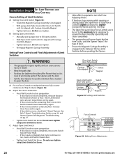
.... • Tighten Set Screw. NOTE • Little effort is required to turn the Force Adjusting Knobs. • If the door stops moving parts of the Opener and the door. • Set the door Opener to use the minimum force needed to open garage door. - Close Limit Switch...; Manually open ) Carriage (disengaged) Magnet Figure 33 Setting Limit Switches Force Controls Figure 34 Making Force Adjustments 20 For Help, call 1-800-35-GENIE or visit www.geniecompany.com A Pre-set to the minimum force necessary to floor. If door does not close garage door. - If door reverses...
.... • Tighten Set Screw. NOTE • Little effort is required to turn the Force Adjusting Knobs. • If the door stops moving parts of the Opener and the door. • Set the door Opener to use the minimum force needed to open garage door. - Close Limit Switch...; Manually open ) Carriage (disengaged) Magnet Figure 33 Setting Limit Switches Force Controls Figure 34 Making Force Adjustments 20 For Help, call 1-800-35-GENIE or visit www.geniecompany.com A Pre-set to the minimum force necessary to floor. If door does not close garage door. - If door reverses...

Owner's Manual
Page 23
... Authorized Dealer for service or call Customer Service at 1-800-35-GENIE. D Installation is 3' - 4' above the ground, the door should stay open. Release Magnetic Carriage Assembly from Drive Screw. • Lubricate Drive Screw with Part 15 of Motor Cover MAINTENANCE A Monthly Door springs and door hardware: - B Yearly: • Wipe off old excess...
... Authorized Dealer for service or call Customer Service at 1-800-35-GENIE. D Installation is 3' - 4' above the ground, the door should stay open. Release Magnetic Carriage Assembly from Drive Screw. • Lubricate Drive Screw with Part 15 of Motor Cover MAINTENANCE A Monthly Door springs and door hardware: - B Yearly: • Wipe off old excess...

Owner's Manual
Page 28
... out of balance • Broken springs or cables • Power outages • Use of extension cords • Missing or damaged parts on your Genie product, and it -yourself repairs. Your choice of one of God • Failure to send a replacement unit, we choose to ...Owner's Manual. Who Gets the Warranty? If we will not reimburse you may not apply. Lifetime* on parts. If an Authorized dealer provides warranty service, Genie will send replacement parts or, at our option, a replacement unit at 1-800-654-3643. Limitations: IMPLIED WARRANTIES, INCLUDING THOSE ...
... out of balance • Broken springs or cables • Power outages • Use of extension cords • Missing or damaged parts on your Genie product, and it -yourself repairs. Your choice of one of God • Failure to send a replacement unit, we choose to ...Owner's Manual. Who Gets the Warranty? If we will not reimburse you may not apply. Lifetime* on parts. If an Authorized dealer provides warranty service, Genie will send replacement parts or, at our option, a replacement unit at 1-800-654-3643. Limitations: IMPLIED WARRANTIES, INCLUDING THOSE ...
