
Manual
Page 1
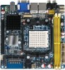
GA-2AIEV-RH GA-2AIEV2-RH GA-2AIEV3-RH AMD® mini-ITX Motherboard USER'S MANUAL AMD® mini-ITX Motherboard Rev. 1001 * The WEEE marking on the product indicates this product must not be disposed of with user's other household waste and must be handed over to a designated collection point for the recycling of waste electrical and electronic equipment!! * The WEEE marking applies only in European Union's member states.
GA-2AIEV-RH GA-2AIEV2-RH GA-2AIEV3-RH AMD® mini-ITX Motherboard USER'S MANUAL AMD® mini-ITX Motherboard Rev. 1001 * The WEEE marking on the product indicates this product must not be disposed of with user's other household waste and must be handed over to a designated collection point for the recycling of waste electrical and electronic equipment!! * The WEEE marking applies only in European Union's member states.

Manual
Page 2
... product information and specifications, please carefully read the "Product User Manual". For detailed information related to Gigabyte's unique features, please go to "Technology Guide" section on Gigabyte's website to their respective companies. GA-2AIEV-RH/GA-2AIEV2-RH/GA-2AIEV3-RH Motherboard Copyright © 2008 GIGA-BYTE TECHNOLOGY CO., LTD. The trademarks mentioned in any form or by...
... product information and specifications, please carefully read the "Product User Manual". For detailed information related to Gigabyte's unique features, please go to "Technology Guide" section on Gigabyte's website to their respective companies. GA-2AIEV-RH/GA-2AIEV2-RH/GA-2AIEV3-RH Motherboard Copyright © 2008 GIGA-BYTE TECHNOLOGY CO., LTD. The trademarks mentioned in any form or by...

Manual
Page 3
... 10 2-2: Installing Processor Colling Fan 11 2-3: Install Memory Modules 12 2-4: Connect ribbon cables, cabinet wires, and power supply 13 2-4-1 : I/O Back Panel Introduction (GA-2AIEV2-RH 13 2-4-2 : I/O Back Panel Introduction (GA-2AIEV-RH/GA-2AIEV3-RH 14 2-5: Connectors Introduction 19 2-6: Block Diagram 28 Chapter 3 BIOS Setup 29 Main ...31 Advanced ...34 SystemInformation 35 CPU Feature 36 Advanced Chipset...
... 10 2-2: Installing Processor Colling Fan 11 2-3: Install Memory Modules 12 2-4: Connect ribbon cables, cabinet wires, and power supply 13 2-4-1 : I/O Back Panel Introduction (GA-2AIEV2-RH 13 2-4-2 : I/O Back Panel Introduction (GA-2AIEV-RH/GA-2AIEV3-RH 14 2-5: Connectors Introduction 19 2-6: Block Diagram 28 Chapter 3 BIOS Setup 29 Main ...31 Advanced ...34 SystemInformation 35 CPU Feature 36 Advanced Chipset...
Manual
Page 4
... GA-2AIEV-RH motherboard (for GA--2AIEV-RH motherboard) The GA-2AIEV2-RH motherboard (for GA--2AIEV2-RH motherboard) The GA-2AIEV3-RH motherboard (for GA--2AIEV3-RH motherboard) Serial ATA cable x 2 I/O Shield Kit CD for motherboard driver & utility GA--2AIEV-RH Quick Reference Guide (for GA--2AIEV-RH motherboard) GA--2AIEV2-RH Quick Reference Guide (for GA--2AIEV2-RH motherboard) GA--2AIEV3-RH Quick Reference Guide (for GA...
... GA-2AIEV-RH motherboard (for GA--2AIEV-RH motherboard) The GA-2AIEV2-RH motherboard (for GA--2AIEV2-RH motherboard) The GA-2AIEV3-RH motherboard (for GA--2AIEV3-RH motherboard) Serial ATA cable x 2 I/O Shield Kit CD for motherboard driver & utility GA--2AIEV-RH Quick Reference Guide (for GA--2AIEV-RH motherboard) GA--2AIEV2-RH Quick Reference Guide (for GA--2AIEV2-RH motherboard) GA--2AIEV3-RH Quick Reference Guide (for GA...

Manual
Page 5
... natural disaster, accident or human cause. 2. Prior to be an unofficial Gigabyte product. 5 Damage as physical harm to the user. 8. If you are connected. 4. Damage due to come in contact with the motherboard circuit or its power cord. 2. GA-2AIEV-RH/GA-2AIEV2-RH/GA-2AIEV3-RH Motherboard Chapter 1 Introduction 1-1 Considerations Prior to Installation Preparing Your Computer The...
... natural disaster, accident or human cause. 2. Prior to be an unofficial Gigabyte product. 5 Damage as physical harm to the user. 8. If you are connected. 4. Damage due to come in contact with the motherboard circuit or its power cord. 2. GA-2AIEV-RH/GA-2AIEV2-RH/GA-2AIEV3-RH Motherboard Chapter 1 Introduction 1-1 Considerations Prior to Installation Preparing Your Computer The...
Manual
Page 6
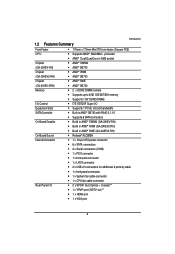
1.2 Features Summary Introduction Form Factor CPU Chipset (GA-2AIEV-RH) Chipset (GA-2AIEV2-RH) Chipset (GA-2AIEV-3RH) Memory I/O Control Expansion Slots SATA Controller On-Board Graphic On-Board Sound Internal Connector Rear Panel I/O 170mm x 170mm Mini...; Built in AMD® SB700 with RAID 0,1,10 Supports 6 SATA connectors Build in AMD® 780MN (GA-2AIEV-RH) Build in AMD® 780M (GA-2AIEV2-RH) Build in AMD® 780E (GA-2AIEV3-RH) Relteak® ALC889A 1 x 24-pin ATX power connector 6 x SATA connectors 2 ...
1.2 Features Summary Introduction Form Factor CPU Chipset (GA-2AIEV-RH) Chipset (GA-2AIEV2-RH) Chipset (GA-2AIEV-3RH) Memory I/O Control Expansion Slots SATA Controller On-Board Graphic On-Board Sound Internal Connector Rear Panel I/O 170mm x 170mm Mini...; Built in AMD® SB700 with RAID 0,1,10 Supports 6 SATA connectors Build in AMD® 780MN (GA-2AIEV-RH) Build in AMD® 780M (GA-2AIEV2-RH) Build in AMD® 780E (GA-2AIEV3-RH) Relteak® ALC889A 1 x 24-pin ATX power connector 6 x SATA connectors 2 ...

Manual
Page 7
GA-2AIEV-RH/GA-2AIEV2-RH/GA-2AIEV3-RH Motherboard 4 x USB 2.0 ports 2 x LAN RJ45 ports 1 HD Audio jacks (Line-out / MIC-in / Line-in) can configure 5.1 channel output by utility **Note** SPDIF Out (Optical + Coaxial) device only for GA-2AIEV2-RH Hardware Monitor Enhanced features with CPU Vcore, 1.5V reference, VCC3 (3.3V) , VBAT3V, +5VSB, CPUA/B Temperature...
GA-2AIEV-RH/GA-2AIEV2-RH/GA-2AIEV3-RH Motherboard 4 x USB 2.0 ports 2 x LAN RJ45 ports 1 HD Audio jacks (Line-out / MIC-in / Line-in) can configure 5.1 channel output by utility **Note** SPDIF Out (Optical + Coaxial) device only for GA-2AIEV2-RH Hardware Monitor Enhanced features with CPU Vcore, 1.5V reference, VCC3 (3.3V) , VBAT3V, +5VSB, CPUA/B Temperature...
Manual
Page 8
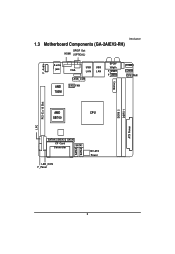
Introduction 1.3 Motherboard Components (GA-2AIEV2-RH) SPDIF Out HDMI (OPTICAL) F_Audio Audio jack AMD 780M USB USB VGA LAN LAN LVDS_CON SYS_FAN SPDIF YPbPr F_USB1 F_USB2 Battery COMA1 COMB1 CPU_FAN DDRII 2 DDRII 1 AMD CPU SB700 LPC PCI -E x 16 Slot ATX Power SATA4 SATA3 SATA2 CF Card Connector SATA1 LED_CON F_Panel SATA5 SATA6 12V ATX Power 8
Introduction 1.3 Motherboard Components (GA-2AIEV2-RH) SPDIF Out HDMI (OPTICAL) F_Audio Audio jack AMD 780M USB USB VGA LAN LAN LVDS_CON SYS_FAN SPDIF YPbPr F_USB1 F_USB2 Battery COMA1 COMB1 CPU_FAN DDRII 2 DDRII 1 AMD CPU SB700 LPC PCI -E x 16 Slot ATX Power SATA4 SATA3 SATA2 CF Card Connector SATA1 LED_CON F_Panel SATA5 SATA6 12V ATX Power 8
Manual
Page 9
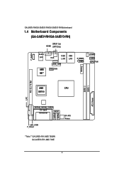
GA-2AIEV-RH/GA-2AIEV2-RH/GA-2AIEV3-RH Motherboard 1.4 Motherboard Components (GA-2AIEV-RH/GA-2AIEV3-RH) SPDIF Out HDMI (OPTICAL) F_Audio Audio jack AMD NB** USB USB VGA LAN LAN LVDS_CON SYS_FAN F_USB1 F_USB2 Battery COMA1 COMB1 CPU_FAN DDRII 2 DDRII 1 AMD CPU SB700 LPC PCI -E x 16 Slot ATX Power SATA4 SATA3 SATA2 CF Card Connector SATA1 LED_CON F_Panel SATA5 SATA6 12V ATX Power **Note** GA-2AIEV-RH: AMD 780MN GA-2AIEV3-RH: AMD 780E 9
GA-2AIEV-RH/GA-2AIEV2-RH/GA-2AIEV3-RH Motherboard 1.4 Motherboard Components (GA-2AIEV-RH/GA-2AIEV3-RH) SPDIF Out HDMI (OPTICAL) F_Audio Audio jack AMD NB** USB USB VGA LAN LAN LVDS_CON SYS_FAN F_USB1 F_USB2 Battery COMA1 COMB1 CPU_FAN DDRII 2 DDRII 1 AMD CPU SB700 LPC PCI -E x 16 Slot ATX Power SATA4 SATA3 SATA2 CF Card Connector SATA1 LED_CON F_Panel SATA5 SATA6 12V ATX Power **Note** GA-2AIEV-RH: AMD 780MN GA-2AIEV3-RH: AMD 780E 9
Manual
Page 11
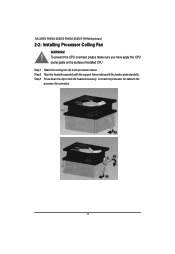
Coonect the processor fan cable to lock the heaksink securely. Step 3 Press down the clip to the processor fan connector. 11 GA-2AIEV-RH/GA-2AIEV2-RH/GA-2AIEV3-RH Motherboard 2-2: Installing Processor Colling Fan WARNING! 㕑 To prevent the CPU overheat, please make sure you have apply the CPU cooler paste on the surface of installed CPU Step 1 Attach the cooling fan clip to the processor scoket. Step 2 Align the heatsink assembly with the support frame mating with the backer plate standoffs.
Coonect the processor fan cable to lock the heaksink securely. Step 3 Press down the clip to the processor fan connector. 11 GA-2AIEV-RH/GA-2AIEV2-RH/GA-2AIEV3-RH Motherboard 2-2: Installing Processor Colling Fan WARNING! 㕑 To prevent the CPU overheat, please make sure you have apply the CPU cooler paste on the surface of installed CPU Step 1 Attach the cooling fan clip to the processor scoket. Step 2 Align the heatsink assembly with the support frame mating with the backer plate standoffs.
Manual
Page 13
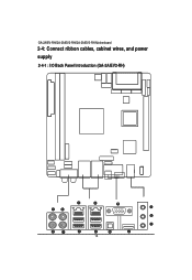
GA-2AIEV-RH/GA-2AIEV2-RH/GA-2AIEV3-RH Motherboard 2-4: Connect ribbon cables, cabinet wires, and power supply 2-4-1 : I/O Back Panel Introduction (GA-2AIEV2-RH) 13
GA-2AIEV-RH/GA-2AIEV2-RH/GA-2AIEV3-RH Motherboard 2-4: Connect ribbon cables, cabinet wires, and power supply 2-4-1 : I/O Back Panel Introduction (GA-2AIEV2-RH) 13

Manual
Page 15
... speeds of 10/100/1000Mbps. For more information please contact your OS supports USB controller. VGA Port Connect the monitor cable to this port. GA-2AIEV-RH/GA-2AIEV2-RH/GA-2AIEV3-RH Motherboard / / YPbPr Ports The "Y," "Pb" and "Pr" are sets of three inputs or outputs on the monitor being used. 15 Also make sure your...
... speeds of 10/100/1000Mbps. For more information please contact your OS supports USB controller. VGA Port Connect the monitor cable to this port. GA-2AIEV-RH/GA-2AIEV2-RH/GA-2AIEV3-RH Motherboard / / YPbPr Ports The "Y," "Pb" and "Pr" are sets of three inputs or outputs on the monitor being used. 15 Also make sure your...
Manual
Page 17
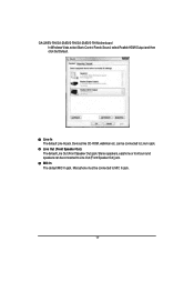
Line In The default Line In jack. can be connected to MIC In jack. 17 Stereo speakers, earphone or front surround speakers can be connected to Line Out (Front Speaker Out) jack. GA-2AIEV-RH/GA-2AIEV2-RH/GA-2AIEV3-RH Motherboard In Windows Vista, select Start>Control Panel>Sound, select Realtek HDMI Output and then click Set Default. MIC In The default MIC In jack. Line Out (Front Speaker Out) The default Line Out (Front Speaker Out) jack. Devices like CD-ROM, walkman etc. Microphone must be connected to Line In jack.
Line In The default Line In jack. can be connected to MIC In jack. 17 Stereo speakers, earphone or front surround speakers can be connected to Line Out (Front Speaker Out) jack. GA-2AIEV-RH/GA-2AIEV2-RH/GA-2AIEV3-RH Motherboard In Windows Vista, select Start>Control Panel>Sound, select Realtek HDMI Output and then click Set Default. MIC In The default MIC In jack. Line Out (Front Speaker Out) The default Line Out (Front Speaker Out) jack. Devices like CD-ROM, walkman etc. Microphone must be connected to Line In jack.
Manual
Page 19
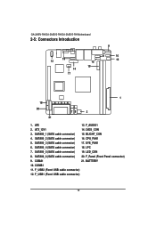
GA-2AIEV-RH/GA-2AIEV2-RH/GA-2AIEV3-RH Motherboard 2-5: Connectors Introduction 13 15 14 17 12 19 9 11 10 16 1 18 654 20 3 78 2 21 1. BLIGHT_CON 4. SYS_FAN1 6. SATAII0_5 (SATA cable connector) 19. F_Panel (...
GA-2AIEV-RH/GA-2AIEV2-RH/GA-2AIEV3-RH Motherboard 2-5: Connectors Introduction 13 15 14 17 12 19 9 11 10 16 1 18 654 20 3 78 2 21 1. BLIGHT_CON 4. SYS_FAN1 6. SATAII0_5 (SATA cable connector) 19. F_Panel (...

Manual
Page 21
Please refer to the BIOS setting for the SATA 3Gb/s and install the proper driver in order to 300MB/s stransfer rate. GA-2AIEV-RH/GA-2AIEV2-RH/GA-2AIEV3-RH Motherboard 3/ 4/ 5/ 6/ 7/ 8 ) SATAII0_1~6 (Serial ATA cable connectors) SATA 3Gb/s can provide up to work properly. 7 7 1 SATA4 SATA3 SATA2 SATA1 1 Pin No. 1 2 3 4 5 6 7 Definition GND TXP TXN GND RXN RXP GND SATA5 SATA6 9/ 10 ) COMA1/COMB1 COMA1 COMB1 2 10 19 Pin No. 1 2 3 4 5 6 7 8 9 10 Definition NDCDNSIN NSOUT NDTRGND NDSRNRTSNCTSNRINo Pin 21
Please refer to the BIOS setting for the SATA 3Gb/s and install the proper driver in order to 300MB/s stransfer rate. GA-2AIEV-RH/GA-2AIEV2-RH/GA-2AIEV3-RH Motherboard 3/ 4/ 5/ 6/ 7/ 8 ) SATAII0_1~6 (Serial ATA cable connectors) SATA 3Gb/s can provide up to work properly. 7 7 1 SATA4 SATA3 SATA2 SATA1 1 Pin No. 1 2 3 4 5 6 7 Definition GND TXP TXN GND RXN RXP GND SATA5 SATA6 9/ 10 ) COMA1/COMB1 COMA1 COMB1 2 10 19 Pin No. 1 2 3 4 5 6 7 8 9 10 Definition NDCDNSIN NSOUT NDTRGND NDSRNRTSNCTSNRINo Pin 21
Manual
Page 23
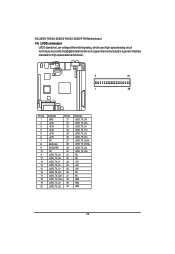
GA-2AIEV-RH/GA-2AIEV2-RH/GA-2AIEV3-RH Motherboard 14) LVDS connector LVDS stands for Low-voltage differential signaling, which uses high-speed analog circuit techniques to provide multigigabit data transfers on copper ...
GA-2AIEV-RH/GA-2AIEV2-RH/GA-2AIEV3-RH Motherboard 14) LVDS connector LVDS stands for Low-voltage differential signaling, which uses high-speed analog circuit techniques to provide multigigabit data transfers on copper ...
Manual
Page 25
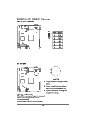
GA-2AIEV-RH/GA-2AIEV2-RH/GA-2AIEV3-RH Motherboard 18 ) LPC (LPC connector) 21 Pin No. If you want to the manufacturer's instructions. Definition 1 FWH33 2 -A_RST 3 -LFRAME 10 9 4 LAD3 5 LAD2 6 LAD1 7 LAD0 8 VCC3 9 ...
GA-2AIEV-RH/GA-2AIEV2-RH/GA-2AIEV3-RH Motherboard 18 ) LPC (LPC connector) 21 Pin No. If you want to the manufacturer's instructions. Definition 1 FWH33 2 -A_RST 3 -LFRAME 10 9 4 LAD3 5 LAD2 6 LAD1 7 LAD0 8 VCC3 9 ...
Manual
Page 27
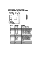
GA-2AIEV-RH/GA-2AIEV2-RH/GA-2AIEV3-RH Motherboard 21 ) LED_CON (Windows Home Server Front Panel connector) 12 1920 Pin No. 1. 2. 3. 4. 5. 6. 7. 8. 9. 10. 11. 12. 13. 14. 15. 16. 17. 18. 19. 20. Signal ...
GA-2AIEV-RH/GA-2AIEV2-RH/GA-2AIEV3-RH Motherboard 21 ) LED_CON (Windows Home Server Front Panel connector) 12 1920 Pin No. 1. 2. 3. 4. 5. 6. 7. 8. 9. 10. 11. 12. 13. 14. 15. 16. 17. 18. 19. 20. Signal ...
Manual
Page 28
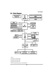
... 66/100/133 I/F CF Card Connector LPC ITE LPC SIO IT8720F TMP 1,2 80 Port COM Port A, B HW Monitor Keyboard/Mouse HW Monitor Keyboard/Mouse **Note** GA-2AIEV-RH: AMD 780MN GA-2AIEV2-RH: AMD 780M GA-2AIEV3-RH: AMD 780E TVOUT connector device only for...
... 66/100/133 I/F CF Card Connector LPC ITE LPC SIO IT8720F TMP 1,2 80 Port COM Port A, B HW Monitor Keyboard/Mouse HW Monitor Keyboard/Mouse **Note** GA-2AIEV-RH: AMD 780MN GA-2AIEV2-RH: AMD 780M GA-2AIEV3-RH: AMD 780E TVOUT connector device only for...

Manual
Page 29
.... CONTROL KEYS Move to previous item Move to next item Move to the item in the left hand Move to the CMOS SETUP screen. GA-2AIEV-RH/GA-2AIEV2-RH/GA-2AIEV3-RH Motherboard Chapter 3 BIOS Setup BIOS (Basic Input and Output System) includes a CMOS SETUP utility which allows user to configure required settings or to Main...
.... CONTROL KEYS Move to previous item Move to next item Move to the item in the left hand Move to the CMOS SETUP screen. GA-2AIEV-RH/GA-2AIEV2-RH/GA-2AIEV3-RH Motherboard Chapter 3 BIOS Setup BIOS (Basic Input and Output System) includes a CMOS SETUP utility which allows user to configure required settings or to Main...


