User Manual
Page 1
GA-5EASV-RH Pentium® 4/D Processor Motherboard USER'S MANUAL Pentium® 4/D Processor Motherboard Rev. 1001 12ME-5EASVRH-1001R * The WEEE marking on the product indicates this product must not be disposed of with user's other household waste and must be handed over to a designated collection point for the recycling of waste electrical and electronic equipment!! * The WEEE marking applies only in European Union's member states.
GA-5EASV-RH Pentium® 4/D Processor Motherboard USER'S MANUAL Pentium® 4/D Processor Motherboard Rev. 1001 12ME-5EASVRH-1001R * The WEEE marking on the product indicates this product must not be disposed of with user's other household waste and must be handed over to a designated collection point for the recycling of waste electrical and electronic equipment!! * The WEEE marking applies only in European Union's member states.

User Manual
Page 2
... Table of Content Item Checklist 4 WARNING 4 Chapter 1 Introduction 5 1.1 Features Summary 5 1.2 GA-5EASV-RH Motherboard Components 8 Chapter 2 Hardware Installation Process 10 2-1: Installing Processor and CPU Haet Sink 10 2-1-1: Installing CPU ...10 2-1-2: Installing Heat Sink 11 2-2: Install Memory Modules 12 2-3: ...
... Table of Content Item Checklist 4 WARNING 4 Chapter 1 Introduction 5 1.1 Features Summary 5 1.2 GA-5EASV-RH Motherboard Components 8 Chapter 2 Hardware Installation Process 10 2-1: Installing Processor and CPU Haet Sink 10 2-1-1: Installing CPU ...10 2-1-2: Installing Heat Sink 11 2-2: Install Memory Modules 12 2-3: ...
User Manual
Page 3
Intel LAN Driver Installation 71 C. Matrix Storgae Manager Utility Installation 80 F. English Table of Content Chapter 4 INTEL RAID BIOS Configuration 63 Chapter 5 Application Driver Installation 68 A. XGI VGA Driver Installation 75 D. DirectX 9.0C Driver Installation 84 Chapter 6 Appendix 87 3 Intel Chipset Software Installation Utilities 68 B. Intel ICH7R RAID Driver Installation 78 E.
Intel LAN Driver Installation 71 C. Matrix Storgae Manager Utility Installation 80 F. English Table of Content Chapter 4 INTEL RAID BIOS Configuration 63 Chapter 5 Application Driver Installation 68 A. XGI VGA Driver Installation 75 D. DirectX 9.0C Driver Installation 84 Chapter 6 Appendix 87 3 Intel Chipset Software Installation Utilities 68 B. Intel ICH7R RAID Driver Installation 78 E.
User Manual
Page 4
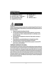
English GA-5EASV-RH Motherboard Item Checklist The GA-5EASV-RH motherboard IDE (ATA100 ) cable x 1 / Floppy cable x 1 CD for motherboard driver & utility GA-5EASV-RH user's manual Serial ATA cable x 4 I/O Shield Kit SATA Power cable x 4 WARNING! Use a grounded wrist strap before you plug in or remove the ATX power connector ...
English GA-5EASV-RH Motherboard Item Checklist The GA-5EASV-RH motherboard IDE (ATA100 ) cable x 1 / Floppy cable x 1 CD for motherboard driver & utility GA-5EASV-RH user's manual Serial ATA cable x 4 I/O Shield Kit SATA Power cable x 4 WARNING! Use a grounded wrist strap before you plug in or remove the ATX power connector ...
User Manual
Page 5
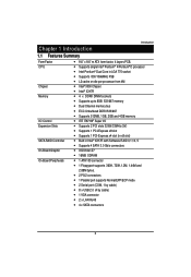
Supports single Intel® Pentium® 4/Pentium® D processor Intel Pentium® Dual Core in Intel® ICH7R with Software RAID 0,1,10, 5 Supports 4 SATA 3.0 Gb/s connectors XGI Volari Z7 16MB SDRAM 1 ATA 100 connector 1 Floppyport supports 360K, 720K,1.2M, 1.44M and 2.88M bytes. 2 PS/2 connectors 1 Parallel port supports Normal/EPP/ECP mode 2 Serial port (COM, 1 by cable) 8 x USB 2.0 (4 by cable) 1 VGA connector 2 x LAN RJ45 4 x SATA connectors 5 Chapter 1 Introduction Introduction 1.1 Features Summary Form Factor CPU Chipset Memory I /O Supports 2 PCI slots 32-Bit/33MHz (...
Supports single Intel® Pentium® 4/Pentium® D processor Intel Pentium® Dual Core in Intel® ICH7R with Software RAID 0,1,10, 5 Supports 4 SATA 3.0 Gb/s connectors XGI Volari Z7 16MB SDRAM 1 ATA 100 connector 1 Floppyport supports 360K, 720K,1.2M, 1.44M and 2.88M bytes. 2 PS/2 connectors 1 Parallel port supports Normal/EPP/ECP mode 2 Serial port (COM, 1 by cable) 8 x USB 2.0 (4 by cable) 1 VGA connector 2 x LAN RJ45 4 x SATA connectors 5 Chapter 1 Introduction Introduction 1.1 Features Summary Form Factor CPU Chipset Memory I /O Supports 2 PCI slots 32-Bit/33MHz (...
User Manual
Page 6
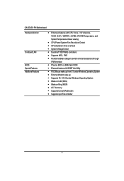
English GA-5EASV-RH Motherboard Hardware Monitor On-Board LAN BIOS Special Features Additional Features Enhanced features with CPU Vcore, 1.5V reference, VCC3 (3.3V) , VBAT3V, +5VSB, CPUA/B Temperature, and ...
English GA-5EASV-RH Motherboard Hardware Monitor On-Board LAN BIOS Special Features Additional Features Enhanced features with CPU Vcore, 1.5V reference, VCC3 (3.3V) , VBAT3V, +5VSB, CPUA/B Temperature, and ...
User Manual
Page 7
Introduction 7
Introduction 7
User Manual
Page 9
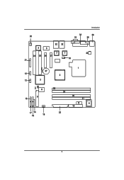
Introduction 20 34 33 36 35 4 5 32 32 7 7 23 24 25 26 27 18 21 1 37 12 2 13 3 8 9 15 17 14 16 19 28 29 22 30 31 11 6 10 9
Introduction 20 34 33 36 35 4 5 32 32 7 7 23 24 25 26 27 18 21 1 37 12 2 13 3 8 9 15 17 14 16 19 28 29 22 30 31 11 6 10 9

User Manual
Page 10
.... 4. Never force the processor into locked position. 10 Please change the insert orientation. 2-1-1: Installing CPU Step 1 Raise the metal locking lever on the socket. English GA-5EASV-RH Motherboard Chapter 2 Hardware Installation Process 2-1: Installing Processor and CPU Haet Sink Before installing the processor and cooling fan, adhere to the following cautions: 1.
.... 4. Never force the processor into locked position. 10 Please change the insert orientation. 2-1-1: Installing CPU Step 1 Raise the metal locking lever on the socket. English GA-5EASV-RH Motherboard Chapter 2 Hardware Installation Process 2-1: Installing Processor and CPU Haet Sink Before installing the processor and cooling fan, adhere to the following cautions: 1.
User Manual
Page 11
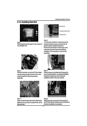
2-1-2: Installing Heat Sink Hardware Installation Process Male Push Pin The top of the installed CPU. Please apply heat sink paste on the surface of Female Push Pin Female Push Pin Step 1. Step 6. Heat sink installation is seated firmly as the picture shown. and reverse the previous step to install the heat sink.) Please note the direction of the heat sink to the heat sink installation section of the user manual) Step. 5 Please check the back side of arrow; Attach the power connector of arrow sign on the male push pin doesn't face inwards before installation. (This instruction is...
2-1-2: Installing Heat Sink Hardware Installation Process Male Push Pin The top of the installed CPU. Please apply heat sink paste on the surface of Female Push Pin Female Push Pin Step 1. Step 6. Heat sink installation is seated firmly as the picture shown. and reverse the previous step to install the heat sink.) Please note the direction of the heat sink to the heat sink installation section of the user manual) Step. 5 Please check the back side of arrow; Attach the power connector of arrow sign on the male push pin doesn't face inwards before installation. (This instruction is...
User Manual
Page 12
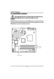
GA-5EASV-RH has 4 dual inline memory module (DIMM) sokcets. Channel B (Red) 12 Channel A (Yellow) English GA-5EASV-RH Motherboard 2-2: Install Memory Modules Before installing the processor and heatsink, adhere to the following warning: When DIMM LED is ON, do not install/remove DIMM from socket. The BIOS will automatically detects memory type and size during system boot. For detail DIMM installation, please refer to the following instructions. It supports Dual Channels Technology.
GA-5EASV-RH has 4 dual inline memory module (DIMM) sokcets. Channel B (Red) 12 Channel A (Yellow) English GA-5EASV-RH Motherboard 2-2: Install Memory Modules Before installing the processor and heatsink, adhere to the following warning: When DIMM LED is ON, do not install/remove DIMM from socket. The BIOS will automatically detects memory type and size during system boot. For detail DIMM installation, please refer to the following instructions. It supports Dual Channels Technology.
User Manual
Page 13
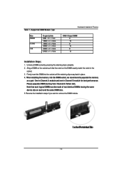
Unlock a DIMM socket by pressing the retaining clips outwards. 2. Note that the notch on each logical DIMM must be made of two identical DIMMs having the same device size on the DIMM exactly match the notch in the socket. 3. Please populate DIMM starting from Channel A (Yellow slot). When installing the memory into the DIMM socket, we recommend to remove the DIMM module. 13 One in Channel A module and one in place. 4. Reverse the installation steps if you want to populate the memory as a pair. Aling a DIMM on the socket such that each and the same DIMM size. 5. Table 1. ...
Unlock a DIMM socket by pressing the retaining clips outwards. 2. Note that the notch on each logical DIMM must be made of two identical DIMMs having the same device size on the DIMM exactly match the notch in the socket. 3. Please populate DIMM starting from Channel A (Yellow slot). When installing the memory into the DIMM socket, we recommend to remove the DIMM module. 13 One in Channel A module and one in place. 4. Reverse the installation steps if you want to populate the memory as a pair. Aling a DIMM on the socket such that each and the same DIMM size. 5. Table 1. ...
User Manual
Page 14
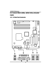
English GA-5EASV-RH Motherboard 2-3: Connect ribbon cables, cabinet wires, and power supply 2-3-1 : I/O Back Panel Introduction 14
English GA-5EASV-RH Motherboard 2-3: Connect ribbon cables, cabinet wires, and power supply 2-3-1 : I/O Back Panel Introduction 14
User Manual
Page 15
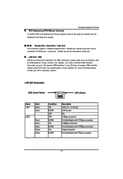
If your device(s) such as USB keyboard, mouse, scanner, zip, speaker...etc. LAN LED Description LED2 (Green/Yellow) LED1 (Green) Name LED1 LED2 Color Green Green Green Green Green Yellow Yellow Condition ON BLINK OFF OFF BLINK ON BLINK ON BLINK Description LAN Link / no Access LAN Access Idle 10Mbps connection Port identification with 10 Mbps connection 100Mbps connection Port identification with 100Mbps connection 1Gbps connection Port identification with 1Gbps connection 15 mouse and modem etc can be connected to Serial port. have a standard USB interface. Device like ...
If your device(s) such as USB keyboard, mouse, scanner, zip, speaker...etc. LAN LED Description LED2 (Green/Yellow) LED1 (Green) Name LED1 LED2 Color Green Green Green Green Green Yellow Yellow Condition ON BLINK OFF OFF BLINK ON BLINK ON BLINK Description LAN Link / no Access LAN Access Idle 10Mbps connection Port identification with 10 Mbps connection 100Mbps connection Port identification with 100Mbps connection 1Gbps connection Port identification with 1Gbps connection 15 mouse and modem etc can be connected to Serial port. have a standard USB interface. Device like ...
User Manual
Page 16
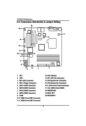
IDE1 (IDE Connector) 4. FDC1 (Floppy Connector) 5. SATA 1 (SATA Connector) 6. COM2 10. CLR_CMOS (Clear CMOS) 18. RECOVERY1 16 UF2 (System Fan Connector) 15. BIOS_WP1 20. English GA-5EASV-RH Motherboard 2-4: Connectors Introduction & Jumper Setting 20 15 2 13 16 10 12 11 18 17 3 6 8 75 19 14 1 9 4 1. BAT1 (Battery) 13. UF3 (System Fan Connector) 16. ...
IDE1 (IDE Connector) 4. FDC1 (Floppy Connector) 5. SATA 1 (SATA Connector) 6. COM2 10. CLR_CMOS (Clear CMOS) 18. RECOVERY1 16 UF2 (System Fan Connector) 15. BIOS_WP1 20. English GA-5EASV-RH Motherboard 2-4: Connectors Introduction & Jumper Setting 20 15 2 13 16 10 12 11 18 17 3 6 8 75 19 14 1 9 4 1. BAT1 (Battery) 13. UF3 (System Fan Connector) 16. ...
User Manual
Page 17
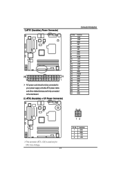
1) ATX1 (Auxukiary Power Connector) 24 13 12 1 AC power cord should only be connected to your power supply unit after ATX power cable and other related devices are firmly connected to the mainboard. 2 ) ATX2 (Auxukiary +12V Power Connector) Connector Introduction PIN No. 1 2 3 4 5 6 7 8 9 10 11 12 13 14 15 16 17 18 19 20 21 22 23 24 Definition +3.3V +3.3V GND +5V GND +5V GND POK 5VSB +12V +12V +3.3V +3.3V -12V GND PSON GND GND GND -5V +5V +5V +5V GND This connector (ATX +12V) is used only for CPU Core Voltage. 17 34 12 Pin No. 1 2 3 4 Definition GND GND +12V +12V
1) ATX1 (Auxukiary Power Connector) 24 13 12 1 AC power cord should only be connected to your power supply unit after ATX power cable and other related devices are firmly connected to the mainboard. 2 ) ATX2 (Auxukiary +12V Power Connector) Connector Introduction PIN No. 1 2 3 4 5 6 7 8 9 10 11 12 13 14 15 16 17 18 19 20 21 22 23 24 Definition +3.3V +3.3V GND +5V GND +5V GND POK 5VSB +12V +12V +3.3V +3.3V -12V GND PSON GND GND GND -5V +5V +5V +5V GND This connector (ATX +12V) is used only for CPU Core Voltage. 17 34 12 Pin No. 1 2 3 4 Definition GND GND +12V +12V
User Manual
Page 18
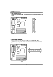
The red stripe of the ribbon cable must be the same side with the Pin1. 1 39 2 40 4 ) FDC1 (Floppy Connector) Please connect the floppy drive ribbon cables to IDE1. The red stripe of the ribbon cable must be the same side with the Pin1. 34 2 33 1 18 It supports 720K,1.2M,1.44M and 2.88Mbytes floppy disk types. English GA-5EASV-RH Motherboard 3 ) IDE1 (IDE Connector) Please connect first harddisk to FDD.
The red stripe of the ribbon cable must be the same side with the Pin1. 1 39 2 40 4 ) FDC1 (Floppy Connector) Please connect the floppy drive ribbon cables to IDE1. The red stripe of the ribbon cable must be the same side with the Pin1. 34 2 33 1 18 It supports 720K,1.2M,1.44M and 2.88Mbytes floppy disk types. English GA-5EASV-RH Motherboard 3 ) IDE1 (IDE Connector) Please connect first harddisk to FDD.
User Manual
Page 19
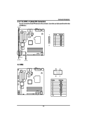
Definition 1 GND 2 TXP 3 TXN 4 GND 5 RXN 6 RXP 7 7 GND SATA3 SATA4 SATA1 9 ) COM2 10 2 91 Pin No. 1 2 3 4 5 6 7 8 9 10 Definition DCDSIN2 SOUT2 DTR2GND DSR2RTS2CTS2RI2NC 19 Connector Introduction 5/ 6/ 7/ 8 ) SATA 1~4 (Serial ATA Connectors) You can connect the Serial ATA device to this connector, it provides you high speed transfer rates (150MB/sec). SATA2 1 Pin No.
Definition 1 GND 2 TXP 3 TXN 4 GND 5 RXN 6 RXP 7 7 GND SATA3 SATA4 SATA1 9 ) COM2 10 2 91 Pin No. 1 2 3 4 5 6 7 8 9 10 Definition DCDSIN2 SOUT2 DTR2GND DSR2RTS2CTS2RI2NC 19 Connector Introduction 5/ 6/ 7/ 8 ) SATA 1~4 (Serial ATA Connectors) You can connect the Serial ATA device to this connector, it provides you high speed transfer rates (150MB/sec). SATA2 1 Pin No.
User Manual
Page 20
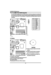
... the power cord. 2.Remove the battery, wait for 30 second. 3.Re-install the battery. 4.Plug the power cord and turn ON the computer. 20 English GA-5EASV-RH Motherboard 10/ 11 ) F_USB1/2 (Front USB Connectors) Be careful with the same or equivalent type recommended by the manufacturer. Check the pin assignment carefully while...
... the power cord. 2.Remove the battery, wait for 30 second. 3.Re-install the battery. 4.Plug the power cord and turn ON the computer. 20 English GA-5EASV-RH Motherboard 10/ 11 ) F_USB1/2 (Front USB Connectors) Be careful with the same or equivalent type recommended by the manufacturer. Check the pin assignment carefully while...
User Manual
Page 21
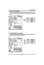
Pin No. These connectors are for system use only. UF3 1 1 Pin No. 1 2 3 4 Definition GND 12V Sense Control UF2 21 Definition 1 GND 1 2 12V 3 Sense 4 Control 14/ 15 ) UF2/3/4/5 (System Fan Connectors) This connector allows you to link with the cooling fan on the system case to prevent the CPU from running under abnormal condition or damaged by overheating.The CPU fan connector supports Max. Connector Introduction 13 ) UF1 (CPU Fan Connectors) Please note, a proper installation of the CPU cooler is essential to lower the system temperature. current up to 1A .
Pin No. These connectors are for system use only. UF3 1 1 Pin No. 1 2 3 4 Definition GND 12V Sense Control UF2 21 Definition 1 GND 1 2 12V 3 Sense 4 Control 14/ 15 ) UF2/3/4/5 (System Fan Connectors) This connector allows you to link with the cooling fan on the system case to prevent the CPU from running under abnormal condition or damaged by overheating.The CPU fan connector supports Max. Connector Introduction 13 ) UF1 (CPU Fan Connectors) Please note, a proper installation of the CPU cooler is essential to lower the system temperature. current up to 1A .