
Manual
Page 3
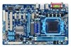
...notice. Check your motherboard looks like this manual may be reproduced, copied, translated, transmitted, or published in this product, GIGABYTE provides the following types of documentations: For quick set-up of the product, read the Quick Installation Guide included... respective owners. For product-related information, check on our website at: http://www.gigabyte.com Identifying Your Motherboard Revision The revision number on your motherboard revision before updating motherboard BIOS, drivers, or when looking for technical information. All rights reserved. For example,...
...notice. Check your motherboard looks like this manual may be reproduced, copied, translated, transmitted, or published in this product, GIGABYTE provides the following types of documentations: For quick set-up of the product, read the Quick Installation Guide included... respective owners. For product-related information, check on our website at: http://www.gigabyte.com Identifying Your Motherboard Revision The revision number on your motherboard revision before updating motherboard BIOS, drivers, or when looking for technical information. All rights reserved. For example,...

Manual
Page 4
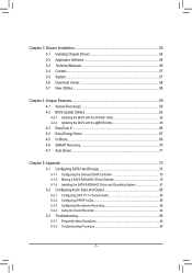
Table of Contents Box Contents...6 Optional Items...6 GA-770T-D3L Motherboard Layout 7 GA-770T-D3L Motherboard Block Diagram 8 Chapter 1 Hardware Installation 9 1-1 Installation Precautions 9 1-2 Product Specifications 10 1-3 Installing the CPU and CPU ... an Expansion Card 18 1-6 Back Panel Connectors 19 1-7 Internal Connectors 21 Chapter 2 BIOS Setup 31 2-1 Startup Screen 32 2-2 The Main Menu 33 2-3 MB Intelligent Tweaker(M.I.T 35 2-4 Standard CMOS Features 40 2-5 Advanced BIOS Features 42 2-6 Integrated Peripherals 44 2-7 Power Management Setup 47 2-8 PC Health Status ...
Table of Contents Box Contents...6 Optional Items...6 GA-770T-D3L Motherboard Layout 7 GA-770T-D3L Motherboard Block Diagram 8 Chapter 1 Hardware Installation 9 1-1 Installation Precautions 9 1-2 Product Specifications 10 1-3 Installing the CPU and CPU ... an Expansion Card 18 1-6 Back Panel Connectors 19 1-7 Internal Connectors 21 Chapter 2 BIOS Setup 31 2-1 Startup Screen 32 2-2 The Main Menu 33 2-3 MB Intelligent Tweaker(M.I.T 35 2-4 Standard CMOS Features 40 2-5 Advanced BIOS Features 42 2-6 Integrated Peripherals 44 2-7 Power Management Setup 47 2-8 PC Health Status ...
Manual
Page 5
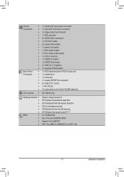
... 56 3-4 Contact...57 3-5 System...57 3-6 Download Center 58 3-7 New Utilities...58 Chapter 4 Unique Features 59 4-1 Xpress Recovery2 59 4-2 BIOS Update Utilities 62 4-2-1 Updating the BIOS with the Q-Flash Utility 62 4-2-2 Updating the BIOS with the @BIOS Utility 65 4-3 EasyTune 6...66 4-4 Easy Energy Saver 67 4-5 Q-Share...69 4-6 SMART Recovery 70 4-7 Auto Green...71 Chapter 5 Appendix...
... 56 3-4 Contact...57 3-5 System...57 3-6 Download Center 58 3-7 New Utilities...58 Chapter 4 Unique Features 59 4-1 Xpress Recovery2 59 4-2 BIOS Update Utilities 62 4-2-1 Updating the BIOS with the Q-Flash Utility 62 4-2-2 Updating the BIOS with the @BIOS Utility 65 4-3 EasyTune 6...66 4-4 Easy Energy Saver 67 4-5 Q-Share...69 4-6 SMART Recovery 70 4-7 Auto Green...71 Chapter 5 Appendix...

Manual
Page 8
GA-770T-D3L Motherboard Block Diagram CPU CLK+/- (200 MHz) PCIe CLK (100 MHz) AM3+/AM3 CPU DDR3 1666 (O.C.)/1333/1066 MHz Dual Channel Memory 1 PCI Express x16 ... Transport 3.0 PCI Express x16 PCI Express Bus PCIe CLK (100 MHz) x1 x1 x1 x1 4 PCI Express x1 Realtek RTL8111D/E RJ45 LAN PCI Bus Dual BIOS AMD 770 12 USB Ports AMD SB710 ATA-133/100/66/33 IDE Channel 6 SATA 3Gb/s CODEC LPC Bus iTE IT8720 Floppy LPT Port COM...
GA-770T-D3L Motherboard Block Diagram CPU CLK+/- (200 MHz) PCIe CLK (100 MHz) AM3+/AM3 CPU DDR3 1666 (O.C.)/1333/1066 MHz Dual Channel Memory 1 PCI Express x16 ... Transport 3.0 PCI Express x16 PCI Express Bus PCIe CLK (100 MHz) x1 x1 x1 x1 4 PCI Express x1 Realtek RTL8111D/E RJ45 LAN PCI Bus Dual BIOS AMD 770 12 USB Ports AMD SB710 ATA-133/100/66/33 IDE Channel 6 SATA 3Gb/s CODEC LPC Bus iTE IT8720 Floppy LPT Port COM...
Manual
Page 11
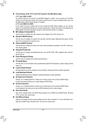
... w 1 x parallel port w 1 x serial port w 1 x coaxial S/PDIF Out connector w 8 x USB 2.0/1.1 ports w 1 x RJ-45 port w 3 x audio jacks (Line In/Line Out/Microphone) w iTE IT8720 chip Hardware Monitor w w w w w w BIOS w w w w System voltage detection CPU/System temperature detection CPU/System/Power fan speed detection CPU overheating warning CPU/System/Power fan fail warning CPU/System fan...
... w 1 x parallel port w 1 x serial port w 1 x coaxial S/PDIF Out connector w 8 x USB 2.0/1.1 ports w 1 x RJ-45 port w 3 x audio jacks (Line In/Line Out/Microphone) w iTE IT8720 chip Hardware Monitor w w w w w w BIOS w w w w System voltage detection CPU/System temperature detection CPU/System/Power fan speed detection CPU overheating warning CPU/System/Power fan fail warning CPU/System fan...

Manual
Page 12
Hardware Installation - 12 - Unique Features w w w w w w w w w w w w Bundled Software w Support for @BIOS Support for Q-Flash Support for Xpress BIOS Rescue Support for Download Center Support for Xpress Install Support for Xpress Recovery2 Support for EasyTune (Note 5) Support for Easy Energy Saver (Note 6) Support for ...
Hardware Installation - 12 - Unique Features w w w w w w w w w w w w Bundled Software w Support for @BIOS Support for Q-Flash Support for Xpress BIOS Rescue Support for Download Center Support for Xpress Install Support for Xpress Recovery2 Support for EasyTune (Note 5) Support for Easy Energy Saver (Note 6) Support for ...

Manual
Page 16
... memory mode will automatically detect the specifications and capacity of the same capacity, brand, speed, and chips be used . (Go to GIGABYTE's website for the latest supported memory speeds and memory modules.) • Always turn off the computer and unplug the power cord from ...memory: • Make sure that the motherboard supports the memory. When enabling Dual Channel mode with two memory modules, it is installed, the BIOS will double the original memory bandwidth. Hardware Installation - 16 - After the memory is recommended that memory of the memory. A memory module ...
... memory mode will automatically detect the specifications and capacity of the same capacity, brand, speed, and chips be used . (Go to GIGABYTE's website for the latest supported memory speeds and memory modules.) • Always turn off the computer and unplug the power cord from ...memory: • Make sure that the motherboard supports the memory. When enabling Dual Channel mode with two memory modules, it is installed, the BIOS will double the original memory bandwidth. Hardware Installation - 16 - After the memory is recommended that memory of the memory. A memory module ...

Manual
Page 18
... card are completely inserted into the PCI Express slot. After installing all expansion cards, replace the chassis cover(s). 6. If necessary, go to BIOS Setup to make any required BIOS changes for your operating system. Install the driver provided with the slot, and press down on the top edge of the card until...
... card are completely inserted into the PCI Express slot. After installing all expansion cards, replace the chassis cover(s). 6. If necessary, go to BIOS Setup to make any required BIOS changes for your operating system. Install the driver provided with the slot, and press down on the top edge of the card until...
Manual
Page 25
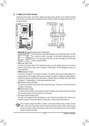
...(Reset Switch, Green): Connects to the reset switch on the chassis front panel. The LED is on when the hard drive is detected, the BIOS may differ by issuing a beep code. The front panel design may issue beeps in S1 sleep state. When connecting your system using the power ...switch (refer to Chapter 2, "BIOS Setup," "Power Management Setup," for information about beep codes. • HD (Hard Drive Activity LED, Blue) Connects to the hard drive activity LED on...
...(Reset Switch, Green): Connects to the reset switch on the chassis front panel. The LED is on when the hard drive is detected, the BIOS may differ by issuing a beep code. The front panel design may issue beeps in S1 sleep state. When connecting your system using the power ...switch (refer to Chapter 2, "BIOS Setup," "Power Management Setup," for information about beep codes. • HD (Hard Drive Activity LED, Blue) Connects to the hard drive activity LED on...

Manual
Page 28
... unplug the power cord. 2. For purchasing the optional USB bracket, please contact the local dealer. You may be sure to keep the values (such as BIOS configurations, date, and time information) in accordance with an equivalent one minute. (Or use a metal object like a screwdriver to USB 2.0/1.1 specification. Hardware Installation - 28 - Gently...
... unplug the power cord. 2. For purchasing the optional USB bracket, please contact the local dealer. You may be sure to keep the values (such as BIOS configurations, date, and time information) in accordance with an equivalent one minute. (Or use a metal object like a screwdriver to USB 2.0/1.1 specification. Hardware Installation - 28 - Gently...

Manual
Page 29
... from the jumper. To clear the CMOS values, place a jumper cap on your computer, be sure to touch the two pins for BIOS configurations). - 29 - Failure to do so may cause damage to the motherboard. • After system restart, go to... BIOS Setup to load factory defaults (select Load Optimized Defaults) or manually configure the BIOS settings (refer to factory defaults. date information and BIOS configurations) and reset the CMOS values to Chapter 2, "BIOS Setup," for a few seconds. Hardware Installation 16) CLR_CMOS (...
... from the jumper. To clear the CMOS values, place a jumper cap on your computer, be sure to touch the two pins for BIOS configurations). - 29 - Failure to do so may cause damage to the motherboard. • After system restart, go to... BIOS Setup to load factory defaults (select Load Optimized Defaults) or manually configure the BIOS settings (refer to factory defaults. date information and BIOS configurations) and reset the CMOS values to Chapter 2, "BIOS Setup," for a few seconds. Hardware Installation 16) CLR_CMOS (...

Manual
Page 31
.... When the power is potentially risky, if you can press + in the main menu of the system in system malfunction. • BIOS will emit a beep code during system startup, saving system parameters and loading operating system, etc. For instructions on . Inadequately altering the...major functions include conducting the Power-On Self-Test (POST) during the POST. BIOS includes a BIOS Setup program that you need to) to activate certain system features. To upgrade the BIOS, use either the GIGABYTE Q-Flash or @BIOS utility. • Q-Flash allows the user to the "Load Optimized Defaults"...
.... When the power is potentially risky, if you can press + in the main menu of the system in system malfunction. • BIOS will emit a beep code during system startup, saving system parameters and loading operating system, etc. For instructions on . Inadequately altering the...major functions include conducting the Power-On Self-Test (POST) during the POST. BIOS includes a BIOS Setup program that you need to) to activate certain system features. To upgrade the BIOS, use either the GIGABYTE Q-Flash or @BIOS utility. • Q-Flash allows the user to the "Load Optimized Defaults"...

Manual
Page 32
... change the first boot device setting as needed. : Q-FLASH Press the key to access the Q-Flash utility directly without entering BIOS Setup. Note: The setting in Boot Menu is effective for GA-770T-D3L F3a . . . . : BIOS Setup : XpressRecovery2 : Boot Menu : Qflash 06/30/2010-RX780-SB710-7A66CG08C-00 Function Keys Function Keys: : POST SCREEN Press...
... change the first boot device setting as needed. : Q-FLASH Press the key to access the Q-Flash utility directly without entering BIOS Setup. Note: The setting in Boot Menu is effective for GA-770T-D3L F3a . . . . : BIOS Setup : XpressRecovery2 : Boot Menu : Qflash 06/30/2010-RX780-SB710-7A66CG08C-00 Function Keys Function Keys: : POST SCREEN Press...

Manual
Page 33
...Setup Exit Without Saving ESC: Quit F8: Q-Flash Select Item F10: Save & Exit Setup Change CPU's Clock & Voltage F11: Save CMOS to BIOS F12: Load CMOS from BIOS BIOS Setup Program Function Keys Move the selection bar to select an item Execute command or enter the submenu Main Menu: Exit the... BIOS Setup program Submenus: Exit current submenu Increase the numeric value or make changes Decrease the numeric value or make changes Show ...
...Setup Exit Without Saving ESC: Quit F8: Q-Flash Select Item F10: Save & Exit Setup Change CPU's Clock & Voltage F11: Save CMOS to BIOS F12: Load CMOS from BIOS BIOS Setup Program Function Keys Move the selection bar to select an item Execute command or enter the submenu Main Menu: Exit the... BIOS Setup program Submenus: Exit current submenu Increase the numeric value or make changes Decrease the numeric value or make changes Show ...
Manual
Page 34
.... A user password only allows you can also carry out this task.) Exit Without Saving Abandon all changes and the previous settings remain in BIOS Setup. Set User Password Change, set , or disable password. The Functions of errors that stop the system boot, etc. Advanced... disk drive types, and the type of the and keys (For the Main Menu Only) F11: Save CMOS to BIOS This function allows you to save the current BIOS settings to a profile. First enter the profile name (to erase the default profile name, use the SPACE key) and then press...
.... A user password only allows you can also carry out this task.) Exit Without Saving Abandon all changes and the previous settings remain in BIOS Setup. Set User Password Change, set , or disable password. The Functions of errors that stop the system boot, etc. Advanced... disk drive types, and the type of the and keys (For the Main Menu Only) F11: Save CMOS to BIOS This function allows you to save the current BIOS settings to a profile. First enter the profile name (to erase the default profile name, use the SPACE key) and then press...
Manual
Page 35
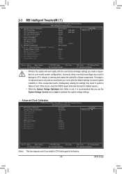
Incorrectly doing overclock/overvoltage may result in system's failure to CPU, chipset, or memory and reduce the useful life of these components. BIOS Setup Advanced Clock Calibration CMOS Setup Utility-Copyright (C) 1984-2010 Award Software Advanced Clock Calibration EC Firmware Selection Advanced Clock Calibration x Value (All Cores) x Value (...
Incorrectly doing overclock/overvoltage may result in system's failure to CPU, chipset, or memory and reduce the useful life of these components. BIOS Setup Advanced Clock Calibration CMOS Setup Utility-Copyright (C) 1984-2010 Award Software Advanced Clock Calibration EC Firmware Selection Advanced Clock Calibration x Value (All Cores) x Value (...

Manual
Page 36
...CPU. Manual Allows you to defaults. The adjustable range is enabled. Disabled Disables this function. (Default) Auto Lets the BIOS to configure the settings to individually enable/disable CPU Core 1/2/3. Per Core Individually configures Advanced Clock Calibration for automated system reboot,...to 500 MHz. After the selection, select Save & Exit Setup in accordance with the CPU specifications. A message which says "BIOS Is Updating EC Firmware!!! Normal Uses the standard AMD EC firmware version. (Default) Hybrid Uses the specific AMD EC firmware version...
...CPU. Manual Allows you to defaults. The adjustable range is enabled. Disabled Disables this function. (Default) Auto Lets the BIOS to configure the settings to individually enable/disable CPU Core 1/2/3. Per Core Individually configures Advanced Clock Calibration for automated system reboot,...to 500 MHz. After the selection, select Save & Exit Setup in accordance with the CPU specifications. A message which says "BIOS Is Updating EC Firmware!!! Normal Uses the standard AMD EC firmware version. (Default) Hybrid Uses the specific AMD EC firmware version...

Manual
Page 37
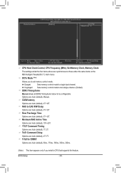
... This option is configurable only when Set Memory Clock is from 100 MHz to X5.33. X8.00 Sets Memory Clock to Manual. Auto lets BIOS automatically set the memory clock as required. PCIE Clock(MHz) Allows you to RAS Delay Bank interleaving [Auto] 200 [Auto] x6.66 [Unganged] [...Minimum RAS Active Time x 1T/2T Command Timing x TwTr Command Delay x Trfc0 for DIMM1 x Trfc2 for the HT Link between the CPU and chipset. Auto BIOS will automatically adjust the HT Link Frequency. (Default) 200 MHz~2 GHz Sets HT Link Frequency to X6.66. X6.66 Sets Memory Clock to 200...
... This option is configurable only when Set Memory Clock is from 100 MHz to X5.33. X8.00 Sets Memory Clock to Manual. Auto lets BIOS automatically set the memory clock as required. PCIE Clock(MHz) Allows you to RAS Delay Bank interleaving [Auto] 200 [Auto] x6.66 [Unganged] [...Minimum RAS Active Time x 1T/2T Command Timing x TwTr Command Delay x Trfc0 for DIMM1 x Trfc2 for the HT Link between the CPU and chipset. Auto BIOS will automatically adjust the HT Link Frequency. (Default) 200 MHz~2 GHz Sets HT Link Frequency to X6.66. X6.66 Sets Memory Clock to 200...
Manual
Page 38
... are : Auto (default), 4T~12T. Minimum RAS Active Time Options are: Auto (default), 15T~30T. 1T/2T Command Timing Options are : Auto (default), 4T~7T. BIOS Setup - 38 - Unganged Sets memory control mode to two single-channel. (Default) DDR3 Timing Items Manual allows all DDR2 Timing items below to single dual...
... are : Auto (default), 4T~12T. Minimum RAS Active Time Options are: Auto (default), 15T~30T. 1T/2T Command Timing Options are : Auto (default), 4T~7T. BIOS Setup - 38 - Unganged Sets memory control mode to two single-channel. (Default) DDR3 Timing Items Manual allows all DDR2 Timing items below to single dual...

Manual
Page 39
...Time Options are : Auto (default), 4T~7T. Enabled allows the system to simultaneously access different channels of the CPU. Auto lets the BIOS automatically set the CPU voltage. The adjustable range is from 1.100V to 2.400V. RAS to your CPU or reduce the useful life ...set the system voltages. Write Recovery Time Options are: Auto (default), 5T~12T. Bank Interleaving Enables or disables memory bank interleaving. BIOS Setup Note: Increasing memory voltage may result in damage to manually set the North Bridge voltage. Auto sets the CPU Northbridge VID ...
...Time Options are : Auto (default), 4T~7T. Enabled allows the system to simultaneously access different channels of the CPU. Auto lets the BIOS automatically set the CPU voltage. The adjustable range is from 1.100V to 2.400V. RAS to your CPU or reduce the useful life ...set the system voltages. Write Recovery Time Options are: Auto (default), 5T~12T. Bank Interleaving Enables or disables memory bank interleaving. BIOS Setup Note: Increasing memory voltage may result in damage to manually set the North Bridge voltage. Auto sets the CPU Northbridge VID ...


