
Manual
Page 5
... of Expansion Cards 18 1-5-1 Graphics Card Support List 18 1-6 I/O Back Panel Introduction 20 1-7 Connectors Introduction 21 Chapter 2 BIOS Setup 31 The Main Menu (For example: BIOS Ver. : GA-8I915MD-G F3a 32 2-1 Standard CMOS Features 34 2-2 Advanced BIOS Features 36 2-3 IntegratedPeripherals 38 2-4 Power Management Setup 40 2-5 PnP/PCI Configurations 41 2-6 PC Health Status 42 2-7 Frequency/Voltage...
... of Expansion Cards 18 1-5-1 Graphics Card Support List 18 1-6 I/O Back Panel Introduction 20 1-7 Connectors Introduction 21 Chapter 2 BIOS Setup 31 The Main Menu (For example: BIOS Ver. : GA-8I915MD-G F3a 32 2-1 Standard CMOS Features 34 2-2 Advanced BIOS Features 36 2-3 IntegratedPeripherals 38 2-4 Power Management Setup 40 2-5 PnP/PCI Configurations 41 2-6 PC Health Status 42 2-7 Frequency/Voltage...

Manual
Page 6
Chapter 3 Drivers Installation 49 3-1 Install Chipset Drivers 49 3-2 SoftwareApplications 50 3-3 Driver CD Information 50 3-4 Hardware Information 51 3-5 Contact Us ...51 Chapter 4 Appendix 53 4-1 Unique Software Utilities 53 4-1-1 EasyTune 5 Introduction 54 4-1-2 Xpress Recovery2 Introduction 55 4-1-3 Flash BIOS Method Introduction 57 4-1-4 2 / 4 / 6 Channel Audio Function Introduction 66 4-2 Troubleshooting 72 - 6 -
Chapter 3 Drivers Installation 49 3-1 Install Chipset Drivers 49 3-2 SoftwareApplications 50 3-3 Driver CD Information 50 3-4 Hardware Information 51 3-5 Contact Us ...51 Chapter 4 Appendix 53 4-1 Unique Software Utilities 53 4-1-1 EasyTune 5 Introduction 54 4-1-2 Xpress Recovery2 Introduction 55 4-1-3 Flash BIOS Method Introduction 57 4-1-4 2 / 4 / 6 Channel Audio Function Introduction 66 4-2 Troubleshooting 72 - 6 -

Manual
Page 7
Only for GA-8I915MD-G. GA-8I915MD-G / GA-8I915MD-GV Motherboard Layout KB_MS ATX_12V LGA775 CPU_FAN ATX CI IDE1 IT8712 COMA GA-8I915MD-G or GA-8I915MD-GV LPT LAN VGA USB DDRII2 PWR_LED F_PANEL USB AUDIO Intel 915G / Intel 915GV PCIE_16 RTL8110S / RTL8100C CD_IN CODEC AUX_IN F_AUDIO SUR_CEN SPDIF_IO COMB PCI1 PCI2 Intel ICH6 PCI3 SYS_FAN F_USB1 F_USB2 DDRII1 FDD SATA1 SATA0 BIOS BAT CLR_CMOS Only for GA-8I915MD-GV. - 7 -
Only for GA-8I915MD-G. GA-8I915MD-G / GA-8I915MD-GV Motherboard Layout KB_MS ATX_12V LGA775 CPU_FAN ATX CI IDE1 IT8712 COMA GA-8I915MD-G or GA-8I915MD-GV LPT LAN VGA USB DDRII2 PWR_LED F_PANEL USB AUDIO Intel 915G / Intel 915GV PCIE_16 RTL8110S / RTL8100C CD_IN CODEC AUX_IN F_AUDIO SUR_CEN SPDIF_IO COMB PCI1 PCI2 Intel ICH6 PCI3 SYS_FAN F_USB1 F_USB2 DDRII1 FDD SATA1 SATA0 BIOS BAT CLR_CMOS Only for GA-8I915MD-GV. - 7 -

Manual
Page 8
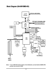
Block Diagram (GA-8I915MD-G) PCI-ECLK (100MHz) LGA775 Processor CPUCLK+/-(200/133MHz) PCI Express x16 VGA PCI Bus RTL8110S RJ45 Host Interface DDRII 600(Note)/533/400MHz DIMM Intel 915G MCH Dual Channel Memory MCHCLK (200/133MHz) 66MHz 33MHz 14.318MHz 48MHz BIOS 2 Serial ATA Intel ATA33/66/100 ICH6 IDE1 Channel Floppy IT8712 LPT Port COM Ports 3 PCI CODEC 8 USB Ports 24MHz 33MHz PS/2 KB/Mouse MIC Line-Out Line-In PCICLK (33MHz) (Note) To use a DDRII 600 memory module on the motherboard, you must install an 800MHz FSB processor and overclock in BIOS. - 8 -
Block Diagram (GA-8I915MD-G) PCI-ECLK (100MHz) LGA775 Processor CPUCLK+/-(200/133MHz) PCI Express x16 VGA PCI Bus RTL8110S RJ45 Host Interface DDRII 600(Note)/533/400MHz DIMM Intel 915G MCH Dual Channel Memory MCHCLK (200/133MHz) 66MHz 33MHz 14.318MHz 48MHz BIOS 2 Serial ATA Intel ATA33/66/100 ICH6 IDE1 Channel Floppy IT8712 LPT Port COM Ports 3 PCI CODEC 8 USB Ports 24MHz 33MHz PS/2 KB/Mouse MIC Line-Out Line-In PCICLK (33MHz) (Note) To use a DDRII 600 memory module on the motherboard, you must install an 800MHz FSB processor and overclock in BIOS. - 8 -
Manual
Page 9
Block Diagram (GA-8I915MD-GV) LGA775 Processor CPUCLK+/-(200/133MHz) VGA PCI-ECLK (100MHz) PCI Express x4 PCI Bus RTL8100C RJ45 Host Interface Intel 915GV MCH DDRII 600(Note)533/400MHz DIMM Dual Channel Memory MCHCLK (200/133MHz) 66MHz 33MHz 14.318MHz 48MHz BIOS 2 Serial ATA Intel ATA33/66/100 ICH6 IDE1 Channel Floppy IT8712 LPT Port COM Ports 3 PCI CODEC 8 USB Ports 24MHz 33MHz PS/2 KB/Mouse MIC Line-Out Line-In PCICLK (33MHz) (Note) To use a DDRII 600 memory module on the motherboard, you must install an 800MHz FSB processor and overclock in BIOS. - 9 -
Block Diagram (GA-8I915MD-GV) LGA775 Processor CPUCLK+/-(200/133MHz) VGA PCI-ECLK (100MHz) PCI Express x4 PCI Bus RTL8100C RJ45 Host Interface Intel 915GV MCH DDRII 600(Note)533/400MHz DIMM Dual Channel Memory MCHCLK (200/133MHz) 66MHz 33MHz 14.318MHz 48MHz BIOS 2 Serial ATA Intel ATA33/66/100 ICH6 IDE1 Channel Floppy IT8712 LPT Port COM Ports 3 PCI CODEC 8 USB Ports 24MHz 33MHz PS/2 KB/Mouse MIC Line-Out Line-In PCICLK (33MHz) (Note) To use a DDRII 600 memory module on the motherboard, you must install an 800MHz FSB processor and overclock in BIOS. - 9 -

Manual
Page 12
...systems Š Realtek ALC655 CODEC Š Supports Line In ; GA-8I915MD-G/GA-8I915MD-GV Motherboard - 12 - The GA-8I915MD-G supports up to PCI Express x 4 mode (please refer to PCI Express x16 mode. Only for GA-8I915MD-GV. Line Out ; Only for GA-8I915MD-G. English 1-2 Feature Summary Motherboard CPU Chipset Memory Slots IDE Connections ... USB 2.0/1.1 ports (rear x 4, front x 4 via cable) Š 1 front audio connector Š 1 PS/2 keyboard port Š 1 PS/2 mouse port Š Built-in BIOS. (Note 2) The GA-8I915MD-GV supports up to the VGA cards support list on page 18~19).
...systems Š Realtek ALC655 CODEC Š Supports Line In ; GA-8I915MD-G/GA-8I915MD-GV Motherboard - 12 - The GA-8I915MD-G supports up to PCI Express x 4 mode (please refer to PCI Express x16 mode. Only for GA-8I915MD-GV. Line Out ; Only for GA-8I915MD-G. English 1-2 Feature Summary Motherboard CPU Chipset Memory Slots IDE Connections ... USB 2.0/1.1 ports (rear x 4, front x 4 via cable) Š 1 front audio connector Š 1 PS/2 keyboard port Š 1 PS/2 mouse port Š Built-in BIOS. (Note 2) The GA-8I915MD-GV supports up to the VGA cards support list on page 18~19).
Manual
Page 13
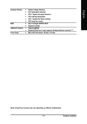
Hardware Installation English Hardware Monitor Š System voltage detection Š CPU temperature detection Š CPU / System fan speed detection Š CPU warning temperature Š CPU / System fan failure warning Š CPU smart fan control BIOS Š Use of licensed AWARD BIOS Š Supports Q-Flash Additional Features Š Supports @BIOS Š Supports EasyTune 5 (only supports Hardware Monitor function)(Note 3) Form Factor Š Micro ATX form factor; 24.4cm x 21.5cm (Note 3) EasyTune functions may vary depending on different motherboards. - 13 -
Hardware Installation English Hardware Monitor Š System voltage detection Š CPU temperature detection Š CPU / System fan speed detection Š CPU warning temperature Š CPU / System fan failure warning Š CPU smart fan control BIOS Š Use of licensed AWARD BIOS Š Supports Q-Flash Additional Features Š Supports @BIOS Š Supports EasyTune 5 (only supports Hardware Monitor function)(Note 3) Form Factor Š Micro ATX form factor; 24.4cm x 21.5cm (Note 3) EasyTune functions may vary depending on different motherboards. - 13 -

Manual
Page 14
...of Hyper-Threading Technology for the peripherals. Fig. 2 Remove the plastic covering on the CPU prior to the CPU during installation.) GA-8I915MD-G/GA-8I915MD-GV Motherboard - 14 - Align the indented corner of the CPU with HT Technology - Please make sure that has optimizations for HT...Pentium 4 Processor with the triangle and gently insert the CPU into position. (Grasping the CPU firmly between the CPU and heatsink. 4. BIOS: A BIOS that supports HT Technology - If this occurs, please change the insert direction of the CPU socket. Chipset: An Intel® Chipset...
...of Hyper-Threading Technology for the peripherals. Fig. 2 Remove the plastic covering on the CPU prior to the CPU during installation.) GA-8I915MD-G/GA-8I915MD-GV Motherboard - 14 - Align the indented corner of the CPU with HT Technology - Please make sure that has optimizations for HT...Pentium 4 Processor with the triangle and gently insert the CPU into position. (Grasping the CPU firmly between the CPU and heatsink. 4. BIOS: A BIOS that supports HT Technology - If this occurs, please change the insert direction of the CPU socket. Chipset: An Intel® Chipset...

Manual
Page 16
GA-8I915MD-G/GA-8I915MD-GV Motherboard - 16 - The motherboard supports DDR II memory modules, whereby BIOS will automatically detect memory capacity and specifications. It is switched off to remove the DIMM module. Memory modules have a foolproof insertion design. If you wish ...
GA-8I915MD-G/GA-8I915MD-GV Motherboard - 16 - The motherboard supports DDR II memory modules, whereby BIOS will automatically detect memory capacity and specifications. It is switched off to remove the DIMM module. Memory modules have a foolproof insertion design. If you wish ...

Manual
Page 18
...shows to secure the slot bracket of expansion card from BIOS. 8. Be sure the metal contacts on the slot. PCI Express x16 Cards Graphics Chip Nvidia Maker Gigabyte Gigabyte Gigabyte Gigabyte Gigabyte Gigabyte Model Name GV-NX53128D GV-NX57128D GV-NX59128D GV-...BIOS utility of the expansion card. 6. To be continued... Power on graphics card.) Figure 1-1. Install related driver from the computer. 3. When using an add-on graphics card, please first delete the onboard graphics driver before install the expansion card into expansion slot in the slot. 5. GA-8I915MD-G/GA-8I915MD...
...shows to secure the slot bracket of expansion card from BIOS. 8. Be sure the metal contacts on the slot. PCI Express x16 Cards Graphics Chip Nvidia Maker Gigabyte Gigabyte Gigabyte Gigabyte Gigabyte Gigabyte Model Name GV-NX53128D GV-NX57128D GV-NX59128D GV-...BIOS utility of the expansion card. 6. To be continued... Power on graphics card.) Figure 1-1. Install related driver from the computer. 3. When using an add-on graphics card, please first delete the onboard graphics driver before install the expansion card into expansion slot in the slot. 5. GA-8I915MD-G/GA-8I915MD...

Manual
Page 24
... connector. Please refer to the BIOS setting for information on settings, please refer to the instructions located on one IDE cable, and the single IDE cable can provide up to two IDE devices (hard drive or optical drive). Definition 1 GND 2 TXP 3 TXN 4 GND 1 7 5 RXN 6 RXP 7 GND GA-8I915MD-G/GA-8I915MD-GV Motherboard - 24 - English 6) IDE1...
... connector. Please refer to the BIOS setting for information on settings, please refer to the instructions located on one IDE cable, and the single IDE cable can provide up to two IDE devices (hard drive or optical drive). Definition 1 GND 2 TXP 3 TXN 4 GND 1 7 5 RXN 6 RXP 7 GND GA-8I915MD-G/GA-8I915MD-GV Motherboard - 24 - English 6) IDE1...

Manual
Page 29
Pin No. English 16) COMB (COMB Connector) Be careful with the polarity of the COMB connector. You can check the "Case Opened" status in BIOS Setup. Check the pin assignments while you connect the COMB cable. Please contact your nearest dealer for optional COMB cable. 2 10 1 9 Pin No. 1 2 3 4 5 6 7 8 9 10 Definition NDCDBNSINB NSOUTB NDTRBGND NDSRBNRTSBNCTSBNRIBNo Pin 17) CI (Chassis Intrusion, Case Open) This 2-pin connector allows your system to detect if the chassis cover is removed. Hardware Installation Definition 1 1 Signal 2 GND - 29 -
Pin No. English 16) COMB (COMB Connector) Be careful with the polarity of the COMB connector. You can check the "Case Opened" status in BIOS Setup. Check the pin assignments while you connect the COMB cable. Please contact your nearest dealer for optional COMB cable. 2 10 1 9 Pin No. 1 2 3 4 5 6 7 8 9 10 Definition NDCDBNSINB NSOUTB NDTRBGND NDSRBNRTSBNCTSBNRIBNo Pin 17) CI (Chassis Intrusion, Case Open) This 2-pin connector allows your system to detect if the chassis cover is removed. Hardware Installation Definition 1 1 Signal 2 GND - 29 -

Manual
Page 31
CONTROL KEYS Move to a new BIOS, either GIGABYTE's Q-Flash or @BIOS utility can enter the BIOS setup screen by pressing "Ctrl + F1". To exit the Help Window press . The CMOS SETUP saves the configuration in the event that BIOS needs to be used. If you wish to upgrade to select item Select Item Main Menu - Quit...
CONTROL KEYS Move to a new BIOS, either GIGABYTE's Q-Flash or @BIOS utility can enter the BIOS setup screen by pressing "Ctrl + F1". To exit the Help Window press . The CMOS SETUP saves the configuration in the event that BIOS needs to be used. If you wish to upgrade to select item Select Item Main Menu - Quit...

Manual
Page 32
...the system parameters which the system would be in the BIOS when somehow the system works not stable as figure below) will appear on the screen. GA-8I915MD-G/GA-8I915MD-GV Motherboard - 32 - If you can't find the setting you enter Award BIOS CMOS Setup Utility, the Main Menu (as usual. The... Main Menu (For example: BIOS Ver. : GA-8I915MD-G F3a) Once you want, please press "Ctrl+F1" to...
...the system parameters which the system would be in the BIOS when somehow the system works not stable as figure below) will appear on the screen. GA-8I915MD-G/GA-8I915MD-GV Motherboard - 32 - If you can't find the setting you enter Award BIOS CMOS Setup Utility, the Main Menu (as usual. The... Main Menu (For example: BIOS Ver. : GA-8I915MD-G F3a) Once you want, please press "Ctrl+F1" to...

Manual
Page 33
BIOS Setup It allows you to limit access to the system. „ Save & Exit Setup Save CMOS value settings to Setup. „ Set User Password Change, set , or disable password. English „ Set Supervisor Password Change, set , or disable password. It allows you to limit access to the system and Setup, or just to CMOS and exit setup. „ Exit Without Saving Abandon all CMOS value changes and exit setup. - 33 -
BIOS Setup It allows you to limit access to the system. „ Save & Exit Setup Save CMOS value settings to Setup. „ Set User Password Change, set , or disable password. English „ Set Supervisor Password Change, set , or disable password. It allows you to limit access to the system and Setup, or just to CMOS and exit setup. „ Exit Without Saving Abandon all CMOS value changes and exit setup. - 33 -
Manual
Page 34
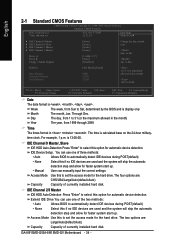
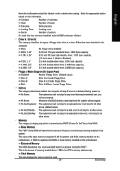
... automatic device detection. IDE Channel 2/3 Master IDE HDD Auto-Detection Press "Enter" to select this to Sat, determined by the BIOS and is calculated base on the 24-hour militarytime clock. The two options are : CHS/LBA/Large/Auto(default:Auto) Capacity...None] [Disabled] Change the day, month, year Sun. Week The week, from 1999 through 2098 Time The times format in . For example, 1 p.m. GA-8I915MD-G/GA-8I915MD-GV Motherboard - 34 - The time is display only Month The month, Jan. Halt On Base Memory Extended Memory Total Memory [All, But Keyboard] 640K 511M...
... automatic device detection. IDE Channel 2/3 Master IDE HDD Auto-Detection Press "Enter" to select this to Sat, determined by the BIOS and is calculated base on the 24-hour militarytime clock. The two options are : CHS/LBA/Large/Auto(default:Auto) Capacity...None] [Disabled] Change the day, month, year Sun. Week The week, from 1999 through 2098 Time The times format in . For example, 1 p.m. GA-8I915MD-G/GA-8I915MD-GV Motherboard - 34 - The time is display only Month The month, Jan. Halt On Base Memory Extended Memory Total Memory [All, But Keyboard] 640K 511M...
Manual
Page 35
... on the motherboard, or 640K for Japan Area) Disabled Normal Floppy Drive. (Default value) Drive A Drive A is the amount of the BIOS. it will stop for any error that may be detected and you will not stop if an error is detected during the POST. Memory The... Write precomp Landing Zone Landing zone Sector Number of base (or conventional) memory installed in the CPU's memory address map. Extended Memory The BIOS determines how much extended memory is 3 mode Floppy Drive. Enter the appropriate option based on the motherboard. All, But Keyboard The system boot...
... on the motherboard, or 640K for Japan Area) Disabled Normal Floppy Drive. (Default value) Drive A Drive A is the amount of the BIOS. it will stop for any error that may be detected and you will not stop if an error is detected during the POST. Memory The... Write precomp Landing Zone Landing zone Sector Number of base (or conventional) memory installed in the CPU's memory address map. Extended Memory The BIOS determines how much extended memory is 3 mode Floppy Drive. Enter the appropriate option based on the motherboard. All, But Keyboard The system boot...

Manual
Page 36
... for onboard(or add-on cards) SCSI, RAID, etc. First / Second / Third Boot Device Floppy Select your boot device priority by Floppy. GA-8I915MD-G/GA-8I915MD-GV Motherboard - 36 - Use < > or < > to select a device, then press to exit this function. Disabled Disable this menu.... priority by CDROM. USB-ZIP Select your boot device priority by USB-ZIP. English 2-2 Advanced BIOS Features CMOS Setup Utility-Copyright (C) 1984-2005 Award Software Advanced BIOS Features ` Hard Disk Boot Priority First Boot Device Second Boot Device Third Boot Device Password Check ...
... for onboard(or add-on cards) SCSI, RAID, etc. First / Second / Third Boot Device Floppy Select your boot device priority by Floppy. GA-8I915MD-G/GA-8I915MD-GV Motherboard - 36 - Use < > or < > to select a device, then press to exit this function. Disabled Disable this menu.... priority by CDROM. USB-ZIP Select your boot device priority by USB-ZIP. English 2-2 Advanced BIOS Features CMOS Setup Utility-Copyright (C) 1984-2005 Award Software Advanced BIOS Features ` Hard Disk Boot Priority First Boot Device Second Boot Device Third Boot Device Password Check ...

Manual
Page 37
... Enhanced Halt (C1E) function. CPU Thermal Monitor 2 (TM2) (Note) Enabled Enable CPU Thermal Monitor 2 (TM2) function.(Default value) Disabled Disable CPU Thermal Monitor 2 (TM2) function. BIOS Setup English CPU Hyper-Threading Enabled Enables CPU Hyper Threading Feature. to 3 Enabled Limit CPUID Maximum value to 32MB. (Note) This item will show up...
... Enhanced Halt (C1E) function. CPU Thermal Monitor 2 (TM2) (Note) Enabled Enable CPU Thermal Monitor 2 (TM2) function.(Default value) Disabled Disable CPU Thermal Monitor 2 (TM2) function. BIOS Setup English CPU Hyper-Threading Enabled Enables CPU Hyper Threading Feature. to 3 Enabled Limit CPUID Maximum value to 32MB. (Note) This item will show up...

Manual
Page 38
...devices will auto set to Ch. 1 Master/Slave, this function will be simulated to Ch. 0 Master/Slave. If PATA IDE were set to PATA mode. GA-8I915MD-G/GA-8I915MD-GV Motherboard - 38 - Set On-Chip SATA mode to Non-Combined, SATA will auto set to Combined, you can use ; 4 SATA HDDs plus PATA HDDs...0 Set to SATA Port 1 Set to Ch. 1 Master/Slave. On-Chip SATA Mode Disabled Auto Combined Enhanced Non-Combined Disable this function will be ignored. BIOS will auto detect. (Default value) Set On-Chip SATA mode to Ch. 0 Master/Slave, this function. If PATA IDE were set to 4 HDDs on ...
...devices will auto set to Ch. 1 Master/Slave, this function will be simulated to Ch. 0 Master/Slave. If PATA IDE were set to PATA mode. GA-8I915MD-G/GA-8I915MD-GV Motherboard - 38 - Set On-Chip SATA mode to Non-Combined, SATA will auto set to Combined, you can use ; 4 SATA HDDs plus PATA HDDs...0 Set to SATA Port 1 Set to Ch. 1 Master/Slave. On-Chip SATA Mode Disabled Auto Combined Enhanced Non-Combined Disable this function will be ignored. BIOS will auto detect. (Default value) Set On-Chip SATA mode to Ch. 0 Master/Slave, this function. If PATA IDE were set to 4 HDDs on ...


