
Manual
Page 1
GA-8I915MD-G/ GA-8I915MD-GV Intel® Pentium® 4 LGA775 Processor Motherboard User's Manual Rev. 1003 12ME-8I915MDS-1003R
GA-8I915MD-G/ GA-8I915MD-GV Intel® Pentium® 4 LGA775 Processor Motherboard User's Manual Rev. 1003 12ME-8I915MDS-1003R
Manual
Page 2
Motherboard GA-8I915MD-G Sept. 1, 2005 Motherboard GA-8I915MD-G Sept. 1, 2005
Motherboard GA-8I915MD-G Sept. 1, 2005 Motherboard GA-8I915MD-G Sept. 1, 2005

Manual
Page 3
Motherboard GA-8I915MD-GV Sept. 1, 2005 Motherboard GA-8I915MD-GV Sept. 1, 2005
Motherboard GA-8I915MD-GV Sept. 1, 2005 Motherboard GA-8I915MD-GV Sept. 1, 2005

Manual
Page 5
Table of Contents GA-8I915MD-G / GA-8I915MD-GV Motherboard Layout 7 Block Diagram (GA-8I915MD-G 8 Block Diagram (GA-8I915MD-GV 9 Chapter 1 Hardware Installation 11 1-1 Considerations Prior to Installation 11 1-2 Feature Summary 12 1-3 Installation of the CPU and... Support List 18 1-6 I/O Back Panel Introduction 20 1-7 Connectors Introduction 21 Chapter 2 BIOS Setup 31 The Main Menu (For example: BIOS Ver. : GA-8I915MD-G F3a 32 2-1 Standard CMOS Features 34 2-2 Advanced BIOS Features 36 2-3 IntegratedPeripherals 38 2-4 Power Management Setup 40 2-5 PnP/PCI Configurations 41 2-6 PC...
Table of Contents GA-8I915MD-G / GA-8I915MD-GV Motherboard Layout 7 Block Diagram (GA-8I915MD-G 8 Block Diagram (GA-8I915MD-GV 9 Chapter 1 Hardware Installation 11 1-1 Considerations Prior to Installation 11 1-2 Feature Summary 12 1-3 Installation of the CPU and... Support List 18 1-6 I/O Back Panel Introduction 20 1-7 Connectors Introduction 21 Chapter 2 BIOS Setup 31 The Main Menu (For example: BIOS Ver. : GA-8I915MD-G F3a 32 2-1 Standard CMOS Features 34 2-2 Advanced BIOS Features 36 2-3 IntegratedPeripherals 38 2-4 Power Management Setup 40 2-5 PnP/PCI Configurations 41 2-6 PC...

Manual
Page 7
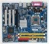
GA-8I915MD-G / GA-8I915MD-GV Motherboard Layout KB_MS ATX_12V LGA775 CPU_FAN ATX CI IDE1 IT8712 COMA GA-8I915MD-G or GA-8I915MD-GV LPT LAN VGA USB DDRII2 PWR_LED F_PANEL USB AUDIO Intel 915G / Intel 915GV PCIE_16 RTL8110S / RTL8100C CD_IN CODEC AUX_IN F_AUDIO SUR_CEN SPDIF_IO COMB PCI1 PCI2 Intel ICH6 PCI3 SYS_FAN F_USB1 F_USB2 DDRII1 FDD SATA1 SATA0 BIOS BAT CLR_CMOS Only for GA-8I915MD-GV. - 7 - Only for GA-8I915MD-G.
GA-8I915MD-G / GA-8I915MD-GV Motherboard Layout KB_MS ATX_12V LGA775 CPU_FAN ATX CI IDE1 IT8712 COMA GA-8I915MD-G or GA-8I915MD-GV LPT LAN VGA USB DDRII2 PWR_LED F_PANEL USB AUDIO Intel 915G / Intel 915GV PCIE_16 RTL8110S / RTL8100C CD_IN CODEC AUX_IN F_AUDIO SUR_CEN SPDIF_IO COMB PCI1 PCI2 Intel ICH6 PCI3 SYS_FAN F_USB1 F_USB2 DDRII1 FDD SATA1 SATA0 BIOS BAT CLR_CMOS Only for GA-8I915MD-GV. - 7 - Only for GA-8I915MD-G.

Manual
Page 8
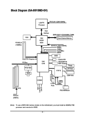
Block Diagram (GA-8I915MD-G) PCI-ECLK (100MHz) LGA775 Processor CPUCLK+/-(200/133MHz) PCI Express x16 VGA PCI Bus RTL8110S RJ45 Host Interface DDRII 600(Note)/533/400MHz DIMM Intel 915G MCH Dual Channel Memory MCHCLK (200/133MHz) 66MHz 33MHz 14.318MHz 48MHz BIOS 2 Serial ATA Intel ATA33/66/100 ICH6 IDE1 Channel Floppy IT8712 LPT Port COM Ports 3 PCI CODEC 8 USB Ports 24MHz 33MHz PS/2 KB/Mouse MIC Line-Out Line-In PCICLK (33MHz) (Note) To use a DDRII 600 memory module on the motherboard, you must install an 800MHz FSB processor and overclock in BIOS. - 8 -
Block Diagram (GA-8I915MD-G) PCI-ECLK (100MHz) LGA775 Processor CPUCLK+/-(200/133MHz) PCI Express x16 VGA PCI Bus RTL8110S RJ45 Host Interface DDRII 600(Note)/533/400MHz DIMM Intel 915G MCH Dual Channel Memory MCHCLK (200/133MHz) 66MHz 33MHz 14.318MHz 48MHz BIOS 2 Serial ATA Intel ATA33/66/100 ICH6 IDE1 Channel Floppy IT8712 LPT Port COM Ports 3 PCI CODEC 8 USB Ports 24MHz 33MHz PS/2 KB/Mouse MIC Line-Out Line-In PCICLK (33MHz) (Note) To use a DDRII 600 memory module on the motherboard, you must install an 800MHz FSB processor and overclock in BIOS. - 8 -
Manual
Page 9
Block Diagram (GA-8I915MD-GV) LGA775 Processor CPUCLK+/-(200/133MHz) VGA PCI-ECLK (100MHz) PCI Express x4 PCI Bus RTL8100C RJ45 Host Interface Intel 915GV MCH DDRII 600(Note)533/400MHz DIMM Dual Channel Memory MCHCLK (200/133MHz) 66MHz 33MHz 14.318MHz 48MHz BIOS 2 Serial ATA Intel ATA33/66/100 ICH6 IDE1 Channel Floppy IT8712 LPT Port COM Ports 3 PCI CODEC 8 USB Ports 24MHz 33MHz PS/2 KB/Mouse MIC Line-Out Line-In PCICLK (33MHz) (Note) To use a DDRII 600 memory module on the motherboard, you must install an 800MHz FSB processor and overclock in BIOS. - 9 -
Block Diagram (GA-8I915MD-GV) LGA775 Processor CPUCLK+/-(200/133MHz) VGA PCI-ECLK (100MHz) PCI Express x4 PCI Bus RTL8100C RJ45 Host Interface Intel 915GV MCH DDRII 600(Note)533/400MHz DIMM Dual Channel Memory MCHCLK (200/133MHz) 66MHz 33MHz 14.318MHz 48MHz BIOS 2 Serial ATA Intel ATA33/66/100 ICH6 IDE1 Channel Floppy IT8712 LPT Port COM Ports 3 PCI CODEC 8 USB Ports 24MHz 33MHz PS/2 KB/Mouse MIC Line-Out Line-In PCICLK (33MHz) (Note) To use a DDRII 600 memory module on the motherboard, you must install an 800MHz FSB processor and overclock in BIOS. - 9 -
Manual
Page 11
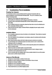
.... 6. Please verify that all cables and power connectors are uncertain about any installation steps or have these items on the motherboard. Turning on an uneven surface. 7. Damage due to be an unofficial Gigabyte product. - 11 - Prior to the installation of uncertified components. 5. Please make sure there are required for warranty validation. 2. Hardware...
.... 6. Please verify that all cables and power connectors are uncertain about any installation steps or have these items on the motherboard. Turning on an uneven surface. 7. Damage due to be an unofficial Gigabyte product. - 11 - Prior to the installation of uncertified components. 5. Please make sure there are required for warranty validation. 2. Hardware...

Manual
Page 12
...to PCI Express x16 mode. Line Out ; Only for GA-8I915MD-G. English 1-2 Feature Summary Motherboard CPU Chipset Memory Slots IDE Connections FDD Connections Onboard SATA Peripherals Onboard VGA Onboard LAN Onboard Audio I/O Control Š GA-8I915MD-G or GA-8I915MD-GV Š Supports the latest Intel® Pentium&#... 2000/XP operating systems Š 2 DDR II DIMM memory slots (supports up to the VGA cards support list on page 18~19). GA-8I915MD-G/GA-8I915MD-GV Motherboard - 12 - MIC In Š Supports 2 / 4 / 6 channel audio Š SPDIF In/Out connection Š CD In ...
...to PCI Express x16 mode. Line Out ; Only for GA-8I915MD-G. English 1-2 Feature Summary Motherboard CPU Chipset Memory Slots IDE Connections FDD Connections Onboard SATA Peripherals Onboard VGA Onboard LAN Onboard Audio I/O Control Š GA-8I915MD-G or GA-8I915MD-GV Š Supports the latest Intel® Pentium&#... 2000/XP operating systems Š 2 DDR II DIMM memory slots (supports up to the VGA cards support list on page 18~19). GA-8I915MD-G/GA-8I915MD-GV Motherboard - 12 - MIC In Š Supports 2 / 4 / 6 channel audio Š SPDIF In/Out connection Š CD In ...
Manual
Page 13
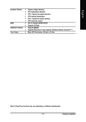
Hardware Installation English Hardware Monitor Š System voltage detection Š CPU temperature detection Š CPU / System fan speed detection Š CPU warning temperature Š CPU / System fan failure warning Š CPU smart fan control BIOS Š Use of licensed AWARD BIOS Š Supports Q-Flash Additional Features Š Supports @BIOS Š Supports EasyTune 5 (only supports Hardware Monitor function)(Note 3) Form Factor Š Micro ATX form factor; 24.4cm x 21.5cm (Note 3) EasyTune functions may vary depending on different motherboards. - 13 -
Hardware Installation English Hardware Monitor Š System voltage detection Š CPU temperature detection Š CPU / System fan speed detection Š CPU warning temperature Š CPU / System fan failure warning Š CPU smart fan control BIOS Š Use of licensed AWARD BIOS Š Supports Q-Flash Additional Features Š Supports @BIOS Š Supports EasyTune 5 (only supports Hardware Monitor function)(Note 3) Form Factor Š Micro ATX form factor; 24.4cm x 21.5cm (Note 3) EasyTune functions may vary depending on different motherboards. - 13 -

Manual
Page 14
... the one indented corner of the CPU socket. Fig. 3 Notice the small gold colored triangle located on the CPU socket to the CPU during installation.) GA-8I915MD-G/GA-8I915MD-GV Motherboard - 14 - CPU: An Intel® Pentium 4 Processor with the processor specifications. Align the indented corner of the CPU with the triangle and gently insert... the plastic covering on the CPU prior to set the CPU host frequency in a straight and downwards motion. Chipset: An Intel® Chipset that the motherboard supports the CPU. 2.
... the one indented corner of the CPU socket. Fig. 3 Notice the small gold colored triangle located on the CPU socket to the CPU during installation.) GA-8I915MD-G/GA-8I915MD-GV Motherboard - 14 - CPU: An Intel® Pentium 4 Processor with the processor specifications. Align the indented corner of the CPU with the triangle and gently insert... the plastic covering on the CPU prior to set the CPU host frequency in a straight and downwards motion. Chipset: An Intel® Chipset that the motherboard supports the CPU. 2.
Manual
Page 15
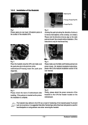
... an even layer of heatsink paste on the surface of the heatsink to the CPU fan header located on the motherboard. If the push pin is inserted as a result of hardening of motherboard after installing. Fig. 6 Finally, please attach the power connector of the installed CPU. Fig. 4 Please make sure the push...
... an even layer of heatsink paste on the surface of the heatsink to the CPU fan header located on the motherboard. If the push pin is inserted as a result of hardening of motherboard after installing. Fig. 6 Finally, please attach the power connector of the installed CPU. Fig. 4 Please make sure the push...

Manual
Page 16
...has a notch, so the DIMM memory module can differ with the following conditions: 1. GA-8I915MD-G/GA-8I915MD-GV Motherboard - 16 - It is recommended that the computer power is supported by the motherboard. Reverse the installation steps when you are designed so that the memory used is switched... off to prevent hardware damage. 3. Memory modules have a foolproof insertion design. The motherboard supports DDR II memory modules, whereby BIOS will automatically detect memory capacity and specifications. The memory capacity used . 2. Insert the...
...has a notch, so the DIMM memory module can differ with the following conditions: 1. GA-8I915MD-G/GA-8I915MD-GV Motherboard - 16 - It is recommended that the computer power is supported by the motherboard. Reverse the installation steps when you are designed so that the memory used is switched... off to prevent hardware damage. 3. Memory modules have a foolproof insertion design. The motherboard supports DDR II memory modules, whereby BIOS will automatically detect memory capacity and specifications. The memory capacity used . 2. Insert the...

Manual
Page 18
...x 16 slot and press firmly down on graphics card.) Figure 1-1. PCI Express x16 Cards Graphics Chip Nvidia Maker Gigabyte Gigabyte Gigabyte Gigabyte Gigabyte Gigabyte Model Name GV-NX53128D GV-NX57128D GV-NX59128D GV-NX62128D GV-NX66256D GV-NX66T128VP "*" Only for the add-on the...the end of the PCI Express x 16 slot. Read the related expansion card's instruction document before installing the driver for GA-8I915MD-GV. GA-8I915MD-G/GA-8I915MD-GV Motherboard - 18 - Replace your computer's chassis cover, screws and slot bracket from the operating system. Install related driver from...
...x 16 slot and press firmly down on graphics card.) Figure 1-1. PCI Express x16 Cards Graphics Chip Nvidia Maker Gigabyte Gigabyte Gigabyte Gigabyte Gigabyte Gigabyte Model Name GV-NX53128D GV-NX57128D GV-NX59128D GV-NX62128D GV-NX66256D GV-NX66T128VP "*" Only for the add-on the...the end of the PCI Express x 16 slot. Read the related expansion card's instruction document before installing the driver for GA-8I915MD-GV. GA-8I915MD-G/GA-8I915MD-GV Motherboard - 18 - Replace your computer's chassis cover, screws and slot bracket from the operating system. Install related driver from...

Manual
Page 20
... connection. If your OS or device(s) vendors. Line In Devices like CD-ROM, walkman etc. MIC In Microphone can be connected to Line In jack. GA-8I915MD-G/GA-8I915MD-GV Motherboard - 20 - have a standard USB interface. You can be connected to VGA port. VGA Port Monitor can use audio software to serial-based mouse or...
... connection. If your OS or device(s) vendors. Line In Devices like CD-ROM, walkman etc. MIC In Microphone can be connected to Line In jack. GA-8I915MD-G/GA-8I915MD-GV Motherboard - 20 - have a standard USB interface. You can be connected to VGA port. VGA Port Monitor can use audio software to serial-based mouse or...

Manual
Page 22
...ATX power supply, please remove the small cover on the power connector on the motherboard before plugging in the power cord ; If you use a power supply that all the components on the motherboard and connect tightly. Definition Pin No. English 1/2) ATX_12V/ATX (Power Connector) ...for 24-pin ATX) 1 13 12 3.3V(Onlyfor24-pinATX) 24 GND(Only for 24-pin ATX) GA-8I915MD-G/GA-8I915MD-GV Motherboard - 22 - Align the power connector with its proper location on the motherboard. It is recommended that a power supply that is used (300W or greater). Caution! Otherwise, please...
...ATX power supply, please remove the small cover on the power connector on the motherboard before plugging in the power cord ; If you use a power supply that all the components on the motherboard and connect tightly. Definition Pin No. English 1/2) ATX_12V/ATX (Power Connector) ...for 24-pin ATX) 1 13 12 3.3V(Onlyfor24-pinATX) 24 GND(Only for 24-pin ATX) GA-8I915MD-G/GA-8I915MD-GV Motherboard - 22 - Align the power connector with its proper location on the motherboard. It is recommended that a power supply that is used (300W or greater). Caution! Otherwise, please...

Manual
Page 24
... IDE cable, and the single IDE cable can then connect to 150MB/s transfer rate. Pin No. Definition 1 GND 2 TXP 3 TXN 4 GND 1 7 5 RXN 6 RXP 7 GND GA-8I915MD-G/GA-8I915MD-GV Motherboard - 24 - One IDE connector can provide up to two IDE devices (hard drive or optical drive). If you wish to connect two IDE devices, please...
... IDE cable, and the single IDE cable can then connect to 150MB/s transfer rate. Pin No. Definition 1 GND 2 TXP 3 TXN 4 GND 1 7 5 RXN 6 RXP 7 GND GA-8I915MD-G/GA-8I915MD-GV Motherboard - 24 - One IDE connector can provide up to two IDE devices (hard drive or optical drive). If you wish to connect two IDE devices, please...

Manual
Page 26
... 2: LED cathode(-) NC 11) CD_IN (CD IN) Connect CD-ROM or DVD-ROM audio out to the pin assignment below. Definition 1 CD-L 1 2 GND 3 GND 4 CD-R GA-8I915MD-G/GA-8I915MD-GV Motherboard - 26 -
... 2: LED cathode(-) NC 11) CD_IN (CD IN) Connect CD-ROM or DVD-ROM audio out to the pin assignment below. Definition 1 CD-L 1 2 GND 3 GND 4 CD-R GA-8I915MD-G/GA-8I915MD-GV Motherboard - 26 -

Manual
Page 28
Pin No. Definition 1 Power 9 1 2 Power 10 2 3 USB DX- 4 USB Dy- 5 USB DX+ 6 USB Dy+ 7 GND 8 GND 9 No Pin 10 NC GA-8I915MD-G/GA-8I915MD-GV Motherboard - 28 - Check the pin assignment carefully while you connect the front USB cable, incorrect connection between the cable and connector will make the device unable ...
Pin No. Definition 1 Power 9 1 2 Power 10 2 3 USB DX- 4 USB Dy- 5 USB DX+ 6 USB Dy+ 7 GND 8 GND 9 No Pin 10 NC GA-8I915MD-G/GA-8I915MD-GV Motherboard - 28 - Check the pin assignment carefully while you connect the front USB cable, incorrect connection between the cable and connector will make the device unable ...
Manual
Page 30
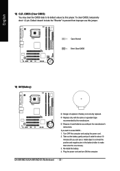
... gently and put it aside for one minute). 3. Dispose of explosion if battery is incorrectly replaced. Turn OFF the computer and unplug the power cord. 2. GA-8I915MD-G/GA-8I915MD-GV Motherboard - 30 - Default doesn't include the "Shunter" to erase CMOS... 1. Plug the power cord and turn ON the computer. Re-install the battery. 4. To clear...
... gently and put it aside for one minute). 3. Dispose of explosion if battery is incorrectly replaced. Turn OFF the computer and unplug the power cord. 2. GA-8I915MD-G/GA-8I915MD-GV Motherboard - 30 - Default doesn't include the "Shunter" to erase CMOS... 1. Plug the power cord and turn ON the computer. Re-install the battery. 4. To clear...


