
Manual
Page 1
GA-8I915MD-G/ GA-8I915MD-GV Intel® Pentium® 4 LGA775 Processor Motherboard User's Manual Rev. 1003 12ME-8I915MDS-1003R
GA-8I915MD-G/ GA-8I915MD-GV Intel® Pentium® 4 LGA775 Processor Motherboard User's Manual Rev. 1003 12ME-8I915MDS-1003R

Manual
Page 3
Motherboard GA-8I915MD-GV Sept. 1, 2005 Motherboard GA-8I915MD-GV Sept. 1, 2005
Motherboard GA-8I915MD-GV Sept. 1, 2005 Motherboard GA-8I915MD-GV Sept. 1, 2005

Manual
Page 5
Table of Contents GA-8I915MD-G / GA-8I915MD-GV Motherboard Layout 7 Block Diagram (GA-8I915MD-G 8 Block Diagram (GA-8I915MD-GV 9 Chapter 1 Hardware Installation 11 1-1 Considerations Prior to Installation 11 1-2 Feature Summary ... I/O Back Panel Introduction 20 1-7 Connectors Introduction 21 Chapter 2 BIOS Setup 31 The Main Menu (For example: BIOS Ver. : GA-8I915MD-G F3a 32 2-1 Standard CMOS Features 34 2-2 Advanced BIOS Features 36 2-3 IntegratedPeripherals 38 2-4 Power Management Setup 40 2-5 PnP/PCI ... & Exit Setup 47 2-12 Exit Without Saving 47 "*" Only for GA-8I915MD-GV. - 5 -
Table of Contents GA-8I915MD-G / GA-8I915MD-GV Motherboard Layout 7 Block Diagram (GA-8I915MD-G 8 Block Diagram (GA-8I915MD-GV 9 Chapter 1 Hardware Installation 11 1-1 Considerations Prior to Installation 11 1-2 Feature Summary ... I/O Back Panel Introduction 20 1-7 Connectors Introduction 21 Chapter 2 BIOS Setup 31 The Main Menu (For example: BIOS Ver. : GA-8I915MD-G F3a 32 2-1 Standard CMOS Features 34 2-2 Advanced BIOS Features 36 2-3 IntegratedPeripherals 38 2-4 Power Management Setup 40 2-5 PnP/PCI ... & Exit Setup 47 2-12 Exit Without Saving 47 "*" Only for GA-8I915MD-GV. - 5 -

Manual
Page 7
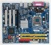
GA-8I915MD-G / GA-8I915MD-GV Motherboard Layout KB_MS ATX_12V LGA775 CPU_FAN ATX CI IDE1 IT8712 COMA GA-8I915MD-G or GA-8I915MD-GV LPT LAN VGA USB DDRII2 PWR_LED F_PANEL USB AUDIO Intel 915G / Intel 915GV PCIE_16 RTL8110S / RTL8100C CD_IN CODEC AUX_IN F_AUDIO SUR_CEN SPDIF_IO COMB PCI1 PCI2 Intel ICH6 PCI3 SYS_FAN F_USB1 F_USB2 DDRII1 FDD SATA1 SATA0 BIOS BAT CLR_CMOS Only for GA-8I915MD-GV. - 7 - Only for GA-8I915MD-G.
GA-8I915MD-G / GA-8I915MD-GV Motherboard Layout KB_MS ATX_12V LGA775 CPU_FAN ATX CI IDE1 IT8712 COMA GA-8I915MD-G or GA-8I915MD-GV LPT LAN VGA USB DDRII2 PWR_LED F_PANEL USB AUDIO Intel 915G / Intel 915GV PCIE_16 RTL8110S / RTL8100C CD_IN CODEC AUX_IN F_AUDIO SUR_CEN SPDIF_IO COMB PCI1 PCI2 Intel ICH6 PCI3 SYS_FAN F_USB1 F_USB2 DDRII1 FDD SATA1 SATA0 BIOS BAT CLR_CMOS Only for GA-8I915MD-GV. - 7 - Only for GA-8I915MD-G.
Manual
Page 9
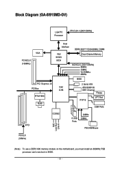
Block Diagram (GA-8I915MD-GV) LGA775 Processor CPUCLK+/-(200/133MHz) VGA PCI-ECLK (100MHz) PCI Express x4 PCI Bus RTL8100C RJ45 Host Interface Intel 915GV MCH DDRII 600(Note)533/400MHz DIMM Dual Channel Memory MCHCLK (200/133MHz) 66MHz 33MHz 14.318MHz 48MHz BIOS 2 Serial ATA Intel ATA33/66/100 ICH6 IDE1 Channel Floppy IT8712 LPT Port COM Ports 3 PCI CODEC 8 USB Ports 24MHz 33MHz PS/2 KB/Mouse MIC Line-Out Line-In PCICLK (33MHz) (Note) To use a DDRII 600 memory module on the motherboard, you must install an 800MHz FSB processor and overclock in BIOS. - 9 -
Block Diagram (GA-8I915MD-GV) LGA775 Processor CPUCLK+/-(200/133MHz) VGA PCI-ECLK (100MHz) PCI Express x4 PCI Bus RTL8100C RJ45 Host Interface Intel 915GV MCH DDRII 600(Note)533/400MHz DIMM Dual Channel Memory MCHCLK (200/133MHz) 66MHz 33MHz 14.318MHz 48MHz BIOS 2 Serial ATA Intel ATA33/66/100 ICH6 IDE1 Channel Floppy IT8712 LPT Port COM Ports 3 PCI CODEC 8 USB Ports 24MHz 33MHz PS/2 KB/Mouse MIC Line-Out Line-In PCICLK (33MHz) (Note) To use a DDRII 600 memory module on the motherboard, you must install an 800MHz FSB processor and overclock in BIOS. - 9 -

Manual
Page 12
...Onboard RTL8100C chip (10/100Mbit) Š 1 RJ 45 port Š Supported on page 18~19). GA-8I915MD-G/GA-8I915MD-GV Motherboard - 12 - Line Out ; Only for GA-8I915MD-GV. English 1-2 Feature Summary Motherboard CPU Chipset Memory Slots IDE Connections FDD Connections Onboard SATA Peripherals Onboard VGA Onboard... LAN Onboard Audio I/O Control Š GA-8I915MD-G or GA-8I915MD-GV Š Supports the latest Intel® Pentium® 4 LGA775 CPU Š Supports 800/533MHz FSB Š...
...Onboard RTL8100C chip (10/100Mbit) Š 1 RJ 45 port Š Supported on page 18~19). GA-8I915MD-G/GA-8I915MD-GV Motherboard - 12 - Line Out ; Only for GA-8I915MD-GV. English 1-2 Feature Summary Motherboard CPU Chipset Memory Slots IDE Connections FDD Connections Onboard SATA Peripherals Onboard VGA Onboard... LAN Onboard Audio I/O Control Š GA-8I915MD-G or GA-8I915MD-GV Š Supports the latest Intel® Pentium® 4 LGA775 CPU Š Supports 800/533MHz FSB Š...

Manual
Page 14
... paste between your computer system requires all of the following conditions: 1. Fig. 2 Remove the plastic covering on the CPU socket to the CPU during installation.) GA-8I915MD-G/GA-8I915MD-GV Motherboard - 14 - It is properly inserted, please replace the load plate and push the metal lever back into position. (Grasping the CPU firmly between the...
... paste between your computer system requires all of the following conditions: 1. Fig. 2 Remove the plastic covering on the CPU socket to the CPU during installation.) GA-8I915MD-G/GA-8I915MD-GV Motherboard - 14 - It is properly inserted, please replace the load plate and push the metal lever back into position. (Grasping the CPU firmly between the...

Manual
Page 16
... socket. Please make sure that they can be inserted only in only one direction. If you wish to insert the module, please switch the direction. GA-8I915MD-G/GA-8I915MD-GV Motherboard - 16 - Notch DDR II Fig.1 The DIMM socket has a notch, so the DIMM memory module can differ with the following conditions: 1. A memory module can...
... socket. Please make sure that they can be inserted only in only one direction. If you wish to insert the module, please switch the direction. GA-8I915MD-G/GA-8I915MD-GV Motherboard - 16 - Notch DDR II Fig.1 The DIMM socket has a notch, so the DIMM memory module can differ with the following conditions: 1. A memory module can...

Manual
Page 17
... mode will add double. To enable Dual Channel mode, please insert two DDR II memory modules (it is installed. 2. The GA-8I915MD-G/GA-8I915MD-GV includes 2 DIMM sockets. English Dual Channel Memory Configuration The GA-8I915MD-G/GA-8I915MD-GV supports the Dual Channel Technology. Hardware Installation After operating the Dual Channel Technology, the bandwidth of Memory Bus will not be...
... mode will add double. To enable Dual Channel mode, please insert two DDR II memory modules (it is installed. 2. The GA-8I915MD-G/GA-8I915MD-GV includes 2 DIMM sockets. English Dual Channel Memory Configuration The GA-8I915MD-G/GA-8I915MD-GV supports the Dual Channel Technology. Hardware Installation After operating the Dual Channel Technology, the bandwidth of Memory Bus will not be...

Manual
Page 18
... Expansion Cards You can install your expansion card by the latch at the end of the PCI Express x 16 slot. GA-8I915MD-G/GA-8I915MD-GV Motherboard - 18 - Be sure the metal contacts on the card are all supported under the Windows XP operating system. ...bracket of expansion card from the operating system. PCI Express x16 Cards Graphics Chip Nvidia Maker Gigabyte Gigabyte Gigabyte Gigabyte Gigabyte Gigabyte Model Name GV-NX53128D GV-NX57128D GV-NX59128D GV-NX62128D GV-NX66256D GV-NX66T128VP "*" Only for the add-on graphics card, please first delete the onboard graphics ...
... Expansion Cards You can install your expansion card by the latch at the end of the PCI Express x 16 slot. GA-8I915MD-G/GA-8I915MD-GV Motherboard - 18 - Be sure the metal contacts on the card are all supported under the Windows XP operating system. ...bracket of expansion card from the operating system. PCI Express x16 Cards Graphics Chip Nvidia Maker Gigabyte Gigabyte Gigabyte Gigabyte Gigabyte Gigabyte Model Name GV-NX53128D GV-NX57128D GV-NX59128D GV-NX62128D GV-NX66256D GV-NX66T128VP "*" Only for the add-on graphics card, please first delete the onboard graphics ...

Manual
Page 20
... peripheral devices. Line Out Connect the stereo speakers or earphone to VGA port. VGA Port Monitor can use audio software to the lower port (purple). GA-8I915MD-G/GA-8I915MD-GV Motherboard - 20 - Also make sure your OS supports USB controller. COMA (Serial Port) Connects to serial-based mouse or data processing devices.
... peripheral devices. Line Out Connect the stereo speakers or earphone to VGA port. VGA Port Monitor can use audio software to the lower port (purple). GA-8I915MD-G/GA-8I915MD-GV Motherboard - 20 - Also make sure your OS supports USB controller. COMA (Serial Port) Connects to serial-based mouse or data processing devices.

Manual
Page 22
... 22 +5V 11 +12V(Onlyfor24-pinATX) 23 +5V (Only for 24-pin ATX) 1 13 12 3.3V(Onlyfor24-pinATX) 24 GND(Only for 24-pin ATX) GA-8I915MD-G/GA-8I915MD-GV Motherboard - 22 - English 1/2) ATX_12V/ATX (Power Connector) With the use of the power connector, the power supply can withstand high power consumption be used that...
... 22 +5V 11 +12V(Onlyfor24-pinATX) 23 +5V (Only for 24-pin ATX) 1 13 12 3.3V(Onlyfor24-pinATX) 24 GND(Only for 24-pin ATX) GA-8I915MD-G/GA-8I915MD-GV Motherboard - 22 - English 1/2) ATX_12V/ATX (Power Connector) With the use of the power connector, the power supply can withstand high power consumption be used that...

Manual
Page 24
... the IDE device). 40 39 2 1 7) SATA0/SATA1 (SATA Connector) SATA can then connect to 150MB/s transfer rate. Definition 1 GND 2 TXP 3 TXN 4 GND 1 7 5 RXN 6 RXP 7 GND GA-8I915MD-G/GA-8I915MD-GV Motherboard - 24 - Pin No. Please refer to the BIOS setting for information on settings, please refer to the instructions located on one IDE cable, and...
... the IDE device). 40 39 2 1 7) SATA0/SATA1 (SATA Connector) SATA can then connect to 150MB/s transfer rate. Definition 1 GND 2 TXP 3 TXN 4 GND 1 7 5 RXN 6 RXP 7 GND GA-8I915MD-G/GA-8I915MD-GV Motherboard - 24 - Pin No. Please refer to the BIOS setting for information on settings, please refer to the instructions located on one IDE cable, and...

Manual
Page 26
... 1: Power Pin 2- Speaker Connector Power Switch Message LED/ Power/ Sleep LED SPEAK- 20 19 SPEAK+ PWPW+ MSGMSG+ 21 NCRES+ RES- Definition 1 CD-L 1 2 GND 3 GND 4 CD-R GA-8I915MD-G/GA-8I915MD-GV Motherboard - 26 - Pin 3: NC Pin 4: Data(-) Open: Normal Close: Reset Hardware System Open: Normal Close: Power On/Off Pin 1: LED anode(+) Pin 2: LED cathode(-) NC...
... 1: Power Pin 2- Speaker Connector Power Switch Message LED/ Power/ Sleep LED SPEAK- 20 19 SPEAK+ PWPW+ MSGMSG+ 21 NCRES+ RES- Definition 1 CD-L 1 2 GND 3 GND 4 CD-R GA-8I915MD-G/GA-8I915MD-GV Motherboard - 26 - Pin 3: NC Pin 4: Data(-) Open: Normal Close: Reset Hardware System Open: Normal Close: Power On/Off Pin 1: LED anode(+) Pin 2: LED cathode(-) NC...

Manual
Page 28
... 14) SUR_CEN Please contact your local dealer. Definition 1 Power 9 1 2 Power 10 2 3 USB DX- 4 USB Dy- 5 USB DX+ 6 USB Dy+ 7 GND 8 GND 9 No Pin 10 NC GA-8I915MD-G/GA-8I915MD-GV Motherboard - 28 - Pin No. For optional front USB cable, please contact your nearest dealer for optional SUR_CEN cable. 26 15 Pin No. 1 2 3 4 5 6 Definition SUR OUTL...
... 14) SUR_CEN Please contact your local dealer. Definition 1 Power 9 1 2 Power 10 2 3 USB DX- 4 USB Dy- 5 USB DX+ 6 USB Dy+ 7 GND 8 GND 9 No Pin 10 NC GA-8I915MD-G/GA-8I915MD-GV Motherboard - 28 - Pin No. For optional front USB cable, please contact your nearest dealer for optional SUR_CEN cable. 26 15 Pin No. 1 2 3 4 5 6 Definition SUR OUTL...
Manual
Page 30
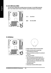
... same or equivalent type recommended by this jumper. 1 Open: Normal 1 Short: Clear CMOS 19) BAT(Battery) Danger of used batteries according to the manufacturer's instructions. GA-8I915MD-G/GA-8I915MD-GV Motherboard - 30 - Dispose of explosion if battery is incorrectly replaced. Default doesn't include the "Shunter" to prevent from improper use a metal object to connect the...
... same or equivalent type recommended by this jumper. 1 Open: Normal 1 Short: Clear CMOS 19) BAT(Battery) Danger of used batteries according to the manufacturer's instructions. GA-8I915MD-G/GA-8I915MD-GV Motherboard - 30 - Dispose of explosion if battery is incorrectly replaced. Default doesn't include the "Shunter" to prevent from improper use a metal object to connect the...

Manual
Page 32
GA-8I915MD-G/GA-8I915MD-GV Motherboard - 32 - English The BIOS Setup menus described in this chapter are for reference only and may differ from the exact settings for stability. „ ... sub-menu. Use arrow keys to select among the items and press to the default for your motherboard. The Main Menu (For example: BIOS Ver. : GA-8I915MD-G F3a) Once you want, please press "Ctrl+F1" to search the advanced option hidden. If you can't find the setting you enter Award BIOS CMOS...
GA-8I915MD-G/GA-8I915MD-GV Motherboard - 32 - English The BIOS Setup menus described in this chapter are for reference only and may differ from the exact settings for stability. „ ... sub-menu. Use arrow keys to select among the items and press to the default for your motherboard. The Main Menu (For example: BIOS Ver. : GA-8I915MD-G F3a) Once you want, please press "Ctrl+F1" to search the advanced option hidden. If you can't find the setting you enter Award BIOS CMOS...
Manual
Page 34
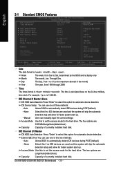
... are : Large/Auto(default:Auto) Capacity Capacity of currently installed hard disk. Through Dec. For example, 1 p.m. Access Mode Use this option for the hard drive. GA-8I915MD-G/GA-8I915MD-GV Motherboard - 34 - IDE Channel 0 Master, Slave IDE HDD Auto-Detection Press "Enter" to select this to 2098 KLJI: Move Enter: Select F5: Previous Values +/-/PU...
... are : Large/Auto(default:Auto) Capacity Capacity of currently installed hard disk. Through Dec. For example, 1 p.m. Access Mode Use this option for the hard drive. GA-8I915MD-G/GA-8I915MD-GV Motherboard - 34 - IDE Channel 0 Master, Slave IDE HDD Auto-Detection Press "Enter" to select this to 2098 KLJI: Move Enter: Select F5: Previous Values +/-/PU...

Manual
Page 36
... ZIP. USB-FDD Select your boot device priority by USB-FDD. USB-CDROM Select your boot device priority by USB-CDROM. Disabled Disable this menu. GA-8I915MD-G/GA-8I915MD-GV Motherboard - 36 - LS120 Select your boot device priority by LS120. Use < > or < > to select a device, then press to move it up when you install the...
... ZIP. USB-FDD Select your boot device priority by USB-FDD. USB-CDROM Select your boot device priority by USB-CDROM. Disabled Disable this menu. GA-8I915MD-G/GA-8I915MD-GV Motherboard - 36 - LS120 Select your boot device priority by LS120. Use < > or < > to select a device, then press to move it up when you install the...

Manual
Page 38
.... (Default value) Disable USB Controller. PATA devices will auto make by the setting "On-Chip SATA Mode" and "PATA IDE Set to Ch. 1 Master/Slave. GA-8I915MD-G/GA-8I915MD-GV Motherboard - 38 - PATA IDE Set to Ch.1 Master/Slave Ch.0 Master/Slave Set PATA IDE to USB Controller USB 2.0 Controller USB Keyboard Support USB Mouse...
.... (Default value) Disable USB Controller. PATA devices will auto make by the setting "On-Chip SATA Mode" and "PATA IDE Set to Ch. 1 Master/Slave. GA-8I915MD-G/GA-8I915MD-GV Motherboard - 38 - PATA IDE Set to Ch.1 Master/Slave Ch.0 Master/Slave Set PATA IDE to USB Controller USB 2.0 Controller USB Keyboard Support USB Mouse...
