User Manual
Page 1
GA-8IAX Pentium Prescott 800 Motherboard USER'S MANUAL Pentium®Prescott Processor Motherboard Rev. 1001 12ME-8IAX-1001
GA-8IAX Pentium Prescott 800 Motherboard USER'S MANUAL Pentium®Prescott Processor Motherboard Rev. 1001 12ME-8IAX-1001
User Manual
Page 2
... of Content Item Checklist 4 WARNING 4 Chapter 1 Introduction 5 Features Summary 5 GA-8IAX Motherboard Layout 7 Chapter 2 Hardware Installation Process 9 Step 1: Installing Processor and CPU Haet Sink 10 Step1-1: Installing CPU 10 Step1-2: Installing Heat Sink 11 Step 2: Install memory ...
... of Content Item Checklist 4 WARNING 4 Chapter 1 Introduction 5 Features Summary 5 GA-8IAX Motherboard Layout 7 Chapter 2 Hardware Installation Process 9 Step 1: Installing Processor and CPU Haet Sink 10 Step1-1: Installing CPU 10 Step1-2: Installing Heat Sink 11 Step 2: Install memory ...
User Manual
Page 4
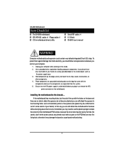
English GA-8IAX Motherboard Item Checklist The GA-8IAX motherboard IDE (ATA133 ) cable x 1 / Floppy cable x 1 CD for motherboard driver & utility Serial ATA cable x 4 I/O Shield GA-8IAX user's manual WARNING! Use a grounded wrist strap before you can still attach the spacers to the base without worrying about ...components are near by the edges and try not touch the IC chips, leads or connectors, or other components. 4. Installing the motherboard to cut off before handling computer components. Just cut the bottom portion of the spacers (the spacer may need to use the plastic...
English GA-8IAX Motherboard Item Checklist The GA-8IAX motherboard IDE (ATA133 ) cable x 1 / Floppy cable x 1 CD for motherboard driver & utility Serial ATA cable x 4 I/O Shield GA-8IAX user's manual WARNING! Use a grounded wrist strap before you can still attach the spacers to the base without worrying about ...components are near by the edges and try not touch the IC chips, leads or connectors, or other components. 4. Installing the motherboard to cut off before handling computer components. Just cut the bottom portion of the spacers (the spacer may need to use the plastic...
User Manual
Page 6
English GA-8IAX Motherboard Additional Features y PS/2 Mouse power on under Windows Operating System y External Modem wake up y Supports S1, S3, S4, S5 under Windows Operating System y Wake on LAN (WOL) y AC Recovery y Supports Console Redirection 6
English GA-8IAX Motherboard Additional Features y PS/2 Mouse power on under Windows Operating System y External Modem wake up y Supports S1, S3, S4, S5 under Windows Operating System y Wake on LAN (WOL) y AC Recovery y Supports Console Redirection 6
User Manual
Page 7
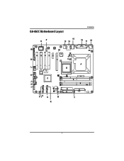
GA-8IAX Motherboard Layout Introduction QP 15 13 14 M 㕡 㕹㖂 6 5 43 2 F N 㕳㕹 1 12 㕺㖀㕢 V 㖀㕳㕣㕹 㖀㕳㕹㕤 L 㕢 &#...
GA-8IAX Motherboard Layout Introduction QP 15 13 14 M 㕡 㕹㖂 6 5 43 2 F N 㕳㕹 1 12 㕺㖀㕢 V 㖀㕳㕣㕹 㖀㕳㕹㕤 L 㕢 &#...
User Manual
Page 8
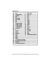
English GA-8IAX Motherboard A. PCIE_16 (x16) B. PCIE_1 (x 4) C. BIOS 4. Broadcom 5751 6 PCI_4 G. FDD 8. F_1394 (IEEE 1394) 12. ATX_12V M. USB_LAN2 O. ITE IT8712F 17. COMA R. KB_MS (Keyboard and Mouse) S. PCI_1 D. BAT (Li-...
English GA-8IAX Motherboard A. PCIE_16 (x16) B. PCIE_1 (x 4) C. BIOS 4. Broadcom 5751 6 PCI_4 G. FDD 8. F_1394 (IEEE 1394) 12. ATX_12V M. USB_LAN2 O. ITE IT8712F 17. COMA R. KB_MS (Keyboard and Mouse) S. PCI_1 D. BAT (Li-...

User Manual
Page 10
... the CPU with the triangle and gently insert the CPU into the socket in permanent irreparable damage. 2. Step 5 Close the lever, reverse step 1 & 2. 10 English GA-8IAX Motherboard Step 1: Installing Processor and CPU Haet Sink Before installing the processor and cooling fan, adhere to the upper-right position. The processor will cause improper...
... the CPU with the triangle and gently insert the CPU into the socket in permanent irreparable damage. 2. Step 5 Close the lever, reverse step 1 & 2. 10 English GA-8IAX Motherboard Step 1: Installing Processor and CPU Haet Sink Before installing the processor and cooling fan, adhere to the upper-right position. The processor will cause improper...
User Manual
Page 11
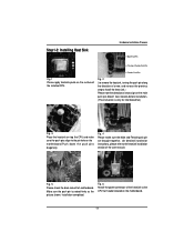
.... 2 ( to the heatsink installation section of the user manual) Fig. 5 Please check the back side of teh motherboard. Fig. 4 Please make sure the push pins align to the CPU fan header located on the motherboard.Push down the push pins diagonally. Installation completed. Step1-2: Installing Heat Sink Hardware Installation Process Male Push... step to install the heat sink.) Please note the direction of arrow sign on the surface of the heatsink to the pin hole on the motherboard. 11
.... 2 ( to the heatsink installation section of the user manual) Fig. 5 Please check the back side of teh motherboard. Fig. 4 Please make sure the push pins align to the CPU fan header located on the motherboard.Push down the push pins diagonally. Installation completed. Step1-2: Installing Heat Sink Hardware Installation Process Male Push... step to install the heat sink.) Please note the direction of arrow sign on the surface of the heatsink to the pin hole on the motherboard. 11
User Manual
Page 12
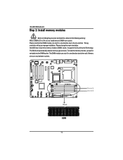
The BIOS will cause improper installation. English GA-8IAX Motherboard Step 2: Install memory modules Before installing the processor and heatsink, adhere to the notch. Wrong orientation will automatically detects memory type and size. Please change the insert orientation. GA-8IAX has 4 dual inline memory module (DIMM) socets. To install the memory module, just push it vertically...
The BIOS will cause improper installation. English GA-8IAX Motherboard Step 2: Install memory modules Before installing the processor and heatsink, adhere to the notch. Wrong orientation will automatically detects memory type and size. Please change the insert orientation. GA-8IAX has 4 dual inline memory module (DIMM) socets. To install the memory module, just push it vertically...
User Manual
Page 14
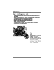
... of the expansion card. 6. Please align the VGA card to install/Uninstall the VGA card. Make sure your computer's chassis cover. 7. English GA-8IAX Motherboard Step 3: Install expansion cards 1. Read the related expansion card's instruction document before install the expansion card into expansion slot in the slot. 5. ...Replace your VGA card is locked by the small white-drawable bar. 14 Power on the card are indeed seated in motherboard. 4. Replace the screw to secure the slot bracket of the PCI Express x 4 slot when you try to the onboard PCI Express x 4...
... of the expansion card. 6. Please align the VGA card to install/Uninstall the VGA card. Make sure your computer's chassis cover. 7. English GA-8IAX Motherboard Step 3: Install expansion cards 1. Read the related expansion card's instruction document before install the expansion card into expansion slot in the slot. 5. ...Replace your VGA card is locked by the small white-drawable bar. 14 Power on the card are indeed seated in motherboard. 4. Replace the screw to secure the slot bracket of the PCI Express x 4 slot when you try to the onboard PCI Express x 4...
User Manual
Page 16
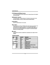
... port and 1 Parallel port. have a standard USB interface. For more information please contact your device(s) such as USB keyboard, mouse, scanner, zip, speaker...etc. English GA-8IAX Motherboard X PS/2 Keyboard and PS/2 Mouse Connector To install a PS/2 port keyboard and mouse, plug the mouse to the upper port (green) and the keyboard to...
... port and 1 Parallel port. have a standard USB interface. For more information please contact your device(s) such as USB keyboard, mouse, scanner, zip, speaker...etc. English GA-8IAX Motherboard X PS/2 Keyboard and PS/2 Mouse Connector To install a PS/2 port keyboard and mouse, plug the mouse to the upper port (green) and the keyboard to...
User Manual
Page 18
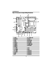
English GA-8IAX Motherboard Step 4-2 :Connectors & Jumper Setting Introduction O N 㕳㕹 P 㕡 㕹㖂 4B 㕺㖀㕢 3 R 㖀㕳㕹㕣 㖀㕳㕹㕤 I 㕢 J 㕡 6 K Q L 㕩&#...
English GA-8IAX Motherboard Step 4-2 :Connectors & Jumper Setting Introduction O N 㕳㕹 P 㕡 㕹㖂 4B 㕺㖀㕢 3 R 㖀㕳㕹㕣 㖀㕳㕹㕤 I 㕢 J 㕡 6 K Q L 㕩&#...
User Manual
Page 20
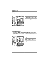
...; 㕩㖝㖝 㕩㖝㖝 㕩㖝㖝 㕧 㕡 㕧 㕡 㕩㖝㖝 㕩㖝㖝 㖃㕾 34 33 2 1 20 English GA-8IAX Motherboard C ) IDE Connector Please connect first harddisk to FDD. It supports 360K,720K,1.2M,1.44M and 2.88Mbytes floppy disk types.
...; 㕩㖝㖝 㕩㖝㖝 㕩㖝㖝 㕧 㕡 㕧 㕡 㕩㖝㖝 㕩㖝㖝 㖃㕾 34 33 2 1 20 English GA-8IAX Motherboard C ) IDE Connector Please connect first harddisk to FDD. It supports 360K,720K,1.2M,1.44M and 2.88Mbytes floppy disk types.
User Manual
Page 22
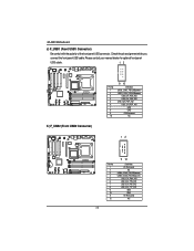
... 11 12 11 12 Definition Pin Removed NC USB4_OC#3_FB(USB power) USB4_OC#3_FB(USB power) USB_ICH_P6N_IND USB_ICH_P7N_IND USB_ICH_P6P_IND USB_ICH_P7P_IND GND GND Pin Removed N/C English GA-8IAX Motherboard J) F_USB1 (Front USB1 Connector) Be careful with the polarity of the front panel USB connector.
... 11 12 11 12 Definition Pin Removed NC USB4_OC#3_FB(USB power) USB4_OC#3_FB(USB power) USB_ICH_P6N_IND USB_ICH_P7N_IND USB_ICH_P6P_IND USB_ICH_P7P_IND GND GND Pin Removed N/C English GA-8IAX Motherboard J) F_USB1 (Front USB1 Connector) Be careful with the polarity of the front panel USB connector.
User Manual
Page 24
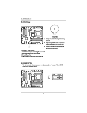
...; 㕩㖝㖝 㕩㖝㖝 㖃㕾 Pin No. BAT Dispose of explosion if battery is incorrectly replaced. Definition 1 GND 2 INTRUDER# 3 NC 1 24 English GA-8IAX Motherboard M ) BAT (Battery) 㕡 㕹㖂 㕳㕹 㖀㕳㕹㕣 㖀㕳㕹㕤 㕢 㕩㖝㖝 㕩㖝㖝 㕧 㕡 㕧...
...; 㕩㖝㖝 㕩㖝㖝 㖃㕾 Pin No. BAT Dispose of explosion if battery is incorrectly replaced. Definition 1 GND 2 INTRUDER# 3 NC 1 24 English GA-8IAX Motherboard M ) BAT (Battery) 㕡 㕹㖂 㕳㕹 㖀㕳㕹㕣 㖀㕳㕹㕤 㕢 㕩㖝㖝 㕩㖝㖝 㕧 㕡 㕧...
User Manual
Page 26
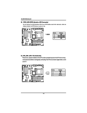
current up to prevent the CPU from running under abnormal condition or damaged by overheating.The CPU fan connector supports Max. English GA-8IAX Motherboard Q) SCSI_LED (SCSI Indicative LED Connector) You can connect the SCSI indicative LED of your SCSI add-on card to this connector, which can indicate whether ...
current up to prevent the CPU from running under abnormal condition or damaged by overheating.The CPU fan connector supports Max. English GA-8IAX Motherboard Q) SCSI_LED (SCSI Indicative LED Connector) You can connect the SCSI indicative LED of your SCSI add-on card to this connector, which can indicate whether ...
User Manual
Page 28
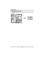
Definition 1 GND 1 2 +12V 3 Sense 28 English GA-8IAX Motherboard U ) PSU_FAN (Power Fan Connector) This connector allows you to link with the cooling fan on the system case to lower the system temperature. 㕳㕹 &#...
Definition 1 GND 1 2 +12V 3 Sense 28 English GA-8IAX Motherboard U ) PSU_FAN (Power Fan Connector) This connector allows you to link with the cooling fan on the system case to lower the system temperature. 㕳㕹 &#...
User Manual
Page 30
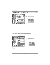
English GA-8IAX Motherboard 3 ) PWR_JP1 (KB_MS connector PS2 Keyboard/Mouse power source selection) 㕡 㕹㖂 1 1-2 close: Default vaule 㕳㕹 㖀㕳㕹㕣 㖀㕳㕹㕤 &#...
English GA-8IAX Motherboard 3 ) PWR_JP1 (KB_MS connector PS2 Keyboard/Mouse power source selection) 㕡 㕹㖂 1 1-2 close: Default vaule 㕳㕹 㖀㕳㕹㕣 㖀㕳㕹㕤 &#...
User Manual
Page 32
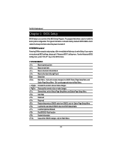
GA-8IAX Motherboard Chapter 3 BIOS Setup BIOS Setup is an overview of information is turned off. ENTERINGSETUP Powering ON the computer and pressing immediately will allow you require ...
GA-8IAX Motherboard Chapter 3 BIOS Setup BIOS Setup is an overview of information is turned off. ENTERINGSETUP Powering ON the computer and pressing immediately will allow you require ...
User Manual
Page 34
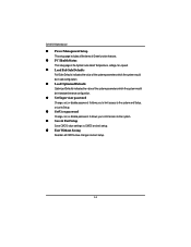
It allows you to limit access to the system. z Save & Exit Setup Save CMOS value settings to Setup. GA-8IAX Motherboard z Power Management Setup This setup page includes all CMOS value changes and exit setup. 34 z Load OptimizedDefaults Optimized Defaults indicates the value of the system ...
It allows you to limit access to the system. z Save & Exit Setup Save CMOS value settings to Setup. GA-8IAX Motherboard z Power Management Setup This setup page includes all CMOS value changes and exit setup. 34 z Load OptimizedDefaults Optimized Defaults indicates the value of the system ...


