

User Manual
Page 1
GA-8IKHXT P4 533/800 Motherboard USER'S MANUAL Pentium®4 Processor Motherboard Rev. 1002
GA-8IKHXT P4 533/800 Motherboard USER'S MANUAL Pentium®4 Processor Motherboard Rev. 1002
User Manual
Page 2
... Table of Content Revision History 4 Item Checklist 4 WARNING 4 Chapter 1 Introduction 5 Features Summary 5 GA-8IKHXT Motherboard Layout 7 Chapter 2 Hardware Installation Process 9 Step 1: Installing Processor and CPU Cooling Fan 10 Step1-1: Installing CPU 10 Step1-2: Installing Cooling Fan 12 Step 2: Install ...
... Table of Content Revision History 4 Item Checklist 4 WARNING 4 Chapter 1 Introduction 5 Features Summary 5 GA-8IKHXT Motherboard Layout 7 Chapter 2 Hardware Installation Process 9 Step 1: Installing Processor and CPU Cooling Fan 10 Step1-1: Installing CPU 10 Step1-2: Installing Cooling Fan 12 Step 2: Install ...
User Manual
Page 4
...don't line up with the components whenever the components are no slots to attach the spacers, do not have one, touch both of the GA-8IKHXT motherboard user's manual. Be careful, don't let the screw contact any printed circuit write or parts on the PCB that came with the ...holes on the base and there are separated from the system. 5. English GA-8IKHXT Motherboard Revision History Revision Revision Note 1.0 Initial release of your hands to a safely grounded object or to isolate the screw from static electricity, ...
...don't line up with the components whenever the components are no slots to attach the spacers, do not have one, touch both of the GA-8IKHXT motherboard user's manual. Be careful, don't let the screw contact any printed circuit write or parts on the PCB that came with the ...holes on the base and there are separated from the system. 5. English GA-8IKHXT Motherboard Revision History Revision Revision Note 1.0 Initial release of your hands to a safely grounded object or to isolate the screw from static electricity, ...
User Manual
Page 5
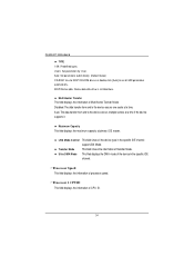
GA-8IKHXT Motherboard: CPU Chipset Memory I/O Control Expansion Slots On-Board IDE On-Board IDE RAID On-Board Peripherals Hardware Monitor Socket 478 for Intel® Micro ...
GA-8IKHXT Motherboard: CPU Chipset Memory I/O Control Expansion Slots On-Board IDE On-Board IDE RAID On-Board Peripherals Hardware Monitor Socket 478 for Intel® Micro ...
User Manual
Page 6
English GA-8IKHXT Motherboard On-Board Vedio Build in ATI Rage XL with 8M SDRAM on board On-Board LAN On-Board USB 2.0 PS/2 Connector BIOS Additional Features Intel 82547GI Gigabit Ethernet Intel 82541GI Gigabit Ethernet Built in Hance Rapids Chipset PS/2 Keyboard interface and PS/2 Mouse interace Phoenix BIOS on 8Mb flash RAM PS/2 Mouse power on under Windows Operating System External Modem wake up Supports S1, S4, S5 under Windows Operating System Wake on LAN (WOL) AC Recovery Supports Console Redirection 6
English GA-8IKHXT Motherboard On-Board Vedio Build in ATI Rage XL with 8M SDRAM on board On-Board LAN On-Board USB 2.0 PS/2 Connector BIOS Additional Features Intel 82547GI Gigabit Ethernet Intel 82541GI Gigabit Ethernet Built in Hance Rapids Chipset PS/2 Keyboard interface and PS/2 Mouse interace Phoenix BIOS on 8Mb flash RAM PS/2 Mouse power on under Windows Operating System External Modem wake up Supports S1, S4, S5 under Windows Operating System Wake on LAN (WOL) AC Recovery Supports Console Redirection 6
User Manual
Page 9
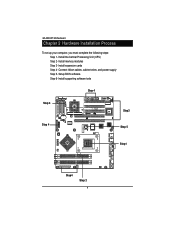
...; 㕡 㖆㕷㕱㕡 Step1 㕶㕱㕾㕥 㕡 Step4 Step 2 9 Install the Central Processing Unit (CPU) Step 2- Install memory modules Step 3- English GA-8IKHXT Motherboard Chapter 2 Hardware Installation Process To set up your computer, you must complete the following steps: Step 1- Install expansion cards Step 4- Connect ribbon cables, cabinet...
...; 㕡 㖆㕷㕱㕡 Step1 㕶㕱㕾㕥 㕡 Step4 Step 2 9 Install the Central Processing Unit (CPU) Step 2- Install memory modules Step 3- English GA-8IKHXT Motherboard Chapter 2 Hardware Installation Process To set up your computer, you must complete the following steps: Step 1- Install expansion cards Step 4- Connect ribbon cables, cabinet...
User Manual
Page 11
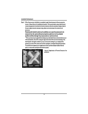
... thermal paste, or remove the cooling fan with the cooling fan, and might pull the processor out of Thermal Grease to installing the heatsink. English GA-8IKHXT Motherboard Step 4. When the processor installation is completed, apply thermal grease to the processor(as shown in Figure 5) prior to the processor. 11 Application of...
... thermal paste, or remove the cooling fan with the cooling fan, and might pull the processor out of Thermal Grease to installing the heatsink. English GA-8IKHXT Motherboard Step 4. When the processor installation is completed, apply thermal grease to the processor(as shown in Figure 5) prior to the processor. 11 Application of...

User Manual
Page 12
Figure 6. Coonect the processor fan cable to the processor fan connector. Coonect the processor fan cable to the processor fan connector. 12 Align the heatsink assembly with the support frame mating with the backer plate standoffs as shown in Figure 6 & 7. Cooling FAN installation. Figure 7. English GA-8IKHXT Motherboard Step1-2: Installing Cooling Fan Step 1. Step 2. Attach th cooling fan clip to the processor scoket.
Figure 6. Coonect the processor fan cable to the processor fan connector. Coonect the processor fan cable to the processor fan connector. 12 Align the heatsink assembly with the support frame mating with the backer plate standoffs as shown in Figure 6 & 7. Cooling FAN installation. Figure 7. English GA-8IKHXT Motherboard Step1-2: Installing Cooling Fan Step 1. Step 2. Attach th cooling fan clip to the processor scoket.
User Manual
Page 14
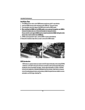
... DRAM subsystem that are suitable for the PC industry that each and the same DIMM size. 5. When installing the DIMM into the DIMM slot. English GA-8IKHXT Motherboard Installation Step: 1. Close the plastic clip at both edges of DDR400/333/266/200 memory solutions, DDR memory is a great evolutionary solution for servers...
... DRAM subsystem that are suitable for the PC industry that each and the same DIMM size. 5. When installing the DIMM into the DIMM slot. English GA-8IKHXT Motherboard Installation Step: 1. Close the plastic clip at both edges of DDR400/333/266/200 memory solutions, DDR memory is a great evolutionary solution for servers...
User Manual
Page 16
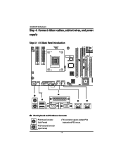
English GA-8IKHXT Motherboard Step 4: Connect ribbon cables, cabinet wires, and power supply Step 4-1 : I/O Back Panel Introduction 㖀㕳㕹㕢 㖀㕳㕹㕡 㕡 㕡 㕱&#...
English GA-8IKHXT Motherboard Step 4: Connect ribbon cables, cabinet wires, and power supply Step 4-1 : I/O Back Panel Introduction 㖀㕳㕹㕢 㖀㕳㕹㕡 㕡 㕡 㕱&#...
User Manual
Page 18
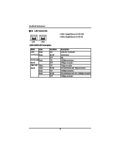
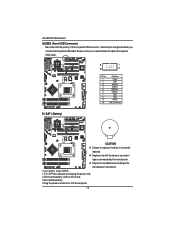
GbE LAN Yellow Speed Yellow Green Green - Condition ON BLINK OFF ON OFF ON BLINK ON BLINK OFF LAN 1: Giagbit Ethernet 10/100/1000 LAN 2: Giagbit Ethernet 10/100/100 Description LAN Link / no Access LAN Access Idle 100Mbps connection 10Mbps connection 1Gbps connection Port identification with 1Gbps connection 100Mbps connection Port identification with 10 or 100Mbps connection 10Mbps connection 18 English GA-8IKHXT Motherboard / LAN Connectors LAN1 LAN2 LAN1/LAN2 LED Description Name Color LAN Green Link/Activity Green - 10/100 LAN Green Speed -
GbE LAN Yellow Speed Yellow Green Green - Condition ON BLINK OFF ON OFF ON BLINK ON BLINK OFF LAN 1: Giagbit Ethernet 10/100/1000 LAN 2: Giagbit Ethernet 10/100/100 Description LAN Link / no Access LAN Access Idle 100Mbps connection 10Mbps connection 1Gbps connection Port identification with 1Gbps connection 100Mbps connection Port identification with 10 or 100Mbps connection 10Mbps connection 18 English GA-8IKHXT Motherboard / LAN Connectors LAN1 LAN2 LAN1/LAN2 LED Description Name Color LAN Green Link/Activity Green - 10/100 LAN Green Speed -
User Manual
Page 20
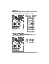
...;㕱㕡 㕱㕲 㕳 㕴 㕵 㕶 㕷 㕸 㕺 㕻 㕼 㖄 㖅 㖆 㖊㕡 㕶㕱㕾㕥 㕡 20 English GA-8IKHXT Motherboard A) ATX (ATX Power Connector) AC power cord should only be connected to your power supply unit after ATX power cable and other related devices...
...;㕱㕡 㕱㕲 㕳 㕴 㕵 㕶 㕷 㕸 㕺 㕻 㕼 㖄 㖅 㖆 㖊㕡 㕶㕱㕾㕥 㕡 20 English GA-8IKHXT Motherboard A) ATX (ATX Power Connector) AC power cord should only be connected to your power supply unit after ATX power cable and other related devices...
User Manual
Page 22
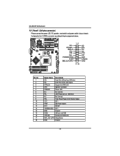
... 1 2 3 4 5 6 7 8 9 10 11 12 13 14 15 16 17 18 Signal Name Description HD+ Hard Disk LED pull up (330 ohm) NC No Connect PW- English GA-8IKHXT Motherboard F) F_Panel1 (2x9 pins connector) Please connect the power LED, PC speaker, reset switch and power switch of your chassis front panel to the F_PANEL...
... 1 2 3 4 5 6 7 8 9 10 11 12 13 14 15 16 17 18 Signal Name Description HD+ Hard Disk LED pull up (330 ohm) NC No Connect PW- English GA-8IKHXT Motherboard F) F_Panel1 (2x9 pins connector) Please connect the power LED, PC speaker, reset switch and power switch of your chassis front panel to the F_PANEL...
User Manual
Page 24
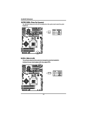
English GA-8IKHXT Motherboard M) PWR_FANIN+ (Power Fan Connector) This connector allows you to link with the cooling fan on LAN) This connector allows the remove servers to lower ...
English GA-8IKHXT Motherboard M) PWR_FANIN+ (Power Fan Connector) This connector allows you to link with the cooling fan on LAN) This connector allows the remove servers to lower ...
User Manual
Page 26
...; 㕡 㖆㕷㕱㕡 㖃㖇㕡 Pin No. 1 2 3 4 5 6 7 8 9 10 Definition Power GND USB DXUSB Dy- Dispose of the front panel USB connector. English GA-8IKHXT Motherboard Q)USB2 (Front USB Connector) Be careful with the same or equivalent type recommended by the manufacturer. Check the pin assignment while you want to...
...; 㕡 㖆㕷㕱㕡 㖃㖇㕡 Pin No. 1 2 3 4 5 6 7 8 9 10 Definition Power GND USB DXUSB Dy- Dispose of the front panel USB connector. English GA-8IKHXT Motherboard Q)USB2 (Front USB Connector) Be careful with the same or equivalent type recommended by the manufacturer. Check the pin assignment while you want to...
User Manual
Page 28
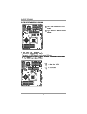
Default value doesn't include the "Shunter" to its default values by this jumper. English GA-8IKHXT Motherboard U ) CI5 ( SCSI Card HDD LED Function) 㕡 㕧 㕡 㕧 㖅㖃㕲㕢 㖀㕳㕹㕥 㖀㕳㕹㕤 㕱㕺 &#...
Default value doesn't include the "Shunter" to its default values by this jumper. English GA-8IKHXT Motherboard U ) CI5 ( SCSI Card HDD LED Function) 㕡 㕧 㕡 㕧 㖅㖃㕲㕢 㖀㕳㕹㕥 㖀㕳㕹㕤 㕱㕺 &#...
User Manual
Page 30
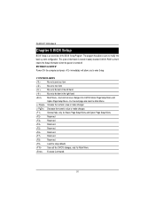
... Commands 30 This type of the BIOS Setup Program. Quit and not save changes into CMOS Status Page Setup Menu and Option Page Setup Menu - GA-8IKHXT Motherboard Chapter 5 BIOS Setup BIOS Setup is turned off. CONTROL KEYS Move to previous item Move to next item Move to the item in the...
... Commands 30 This type of the BIOS Setup Program. Quit and not save changes into CMOS Status Page Setup Menu and Option Page Setup Menu - GA-8IKHXT Motherboard Chapter 5 BIOS Setup BIOS Setup is turned off. CONTROL KEYS Move to previous item Move to next item Move to the item in the...
User Manual
Page 32
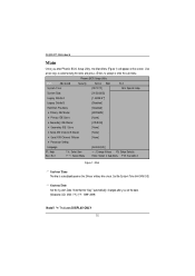
... after you enter Phoenix BIOS Setup Utility, the Main Menu (Figure 1) will appear on the 24-hour military time clock. "ø "Indicates DISPLAY ONLY 32 GA-8IKHXT Motherboard Main Once you set the date. (Weekend: DD: MM: YY) (YY: 1099~2099) Note! ! Use arrow keys to select among the items and press...
... after you enter Phoenix BIOS Setup Utility, the Main Menu (Figure 1) will appear on the 24-hour military time clock. "ø "Indicates DISPLAY ONLY 32 GA-8IKHXT Motherboard Main Once you set the date. (Weekend: DD: MM: YY) (YY: 1099~2099) Note! ! Use arrow keys to select among the items and press...
User Manual
Page 34
...: The data transfer from and to the device occurs multiple sectors at a time. Auto: The data transfer from and to set all HDD parameters automatically . GA-8IKHXT Motherboard 8 TYPE 1-39: Predefined ty pes. Users: Set parameters by User.
...: The data transfer from and to the device occurs multiple sectors at a time. Auto: The data transfer from and to set all HDD parameters automatically . GA-8IKHXT Motherboard 8 TYPE 1-39: Predefined ty pes. Users: Set parameters by User.
User Manual
Page 36
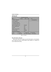
User can change the system's default boot-up sequence, keyboard operation, chipset configuration, PC I configuration and System Hardware health monitoring. 36 GA-8IKHXT Motherboard Advanced Phoenix BIOS Setup Utility Main Adv anced Security Serv er Boot Ex it 4Memory Configuration Item Specific Help 4PCI Configuration 4Peripherial Configuration 4Adv ...
User can change the system's default boot-up sequence, keyboard operation, chipset configuration, PC I configuration and System Hardware health monitoring. 36 GA-8IKHXT Motherboard Advanced Phoenix BIOS Setup Utility Main Adv anced Security Serv er Boot Ex it 4Memory Configuration Item Specific Help 4PCI Configuration 4Peripherial Configuration 4Adv ...

