
Manual
Page 1
GA-EG41MF-US2H LGA775 socket motherboard for Intel® CoreTM processor family/ Intel® Pentium® processor family/Intel® Celeron® processor family User's Manual Rev. 1101 12ME-EG41MFU2H-1101R
GA-EG41MF-US2H LGA775 socket motherboard for Intel® CoreTM processor family/ Intel® Pentium® processor family/Intel® Celeron® processor family User's Manual Rev. 1101 12ME-EG41MFU2H-1101R

Manual
Page 2
Motherboard GA-EG41MF-US2H Mar. 20, 2009 Motherboard GA-EG41MF-US2H Mar. 20, 2009
Motherboard GA-EG41MF-US2H Mar. 20, 2009 Motherboard GA-EG41MF-US2H Mar. 20, 2009

Manual
Page 3
... Example: All rights reserved. Check your motherboard looks like this: "REV: X.X." Changes to their respective owners. For product-related information, check on our website at: http://www.gigabyte.com.tw Identifying Your Motherboard Revision The revision number on our website.... Disclaimer Information in this manual is protected by GIGABYTE without GIGABYTE's prior written permission. Copyright © 2009 GIGA-BYTE TECHNOLOGY...
... Example: All rights reserved. Check your motherboard looks like this: "REV: X.X." Changes to their respective owners. For product-related information, check on our website at: http://www.gigabyte.com.tw Identifying Your Motherboard Revision The revision number on our website.... Disclaimer Information in this manual is protected by GIGABYTE without GIGABYTE's prior written permission. Copyright © 2009 GIGA-BYTE TECHNOLOGY...
Manual
Page 4
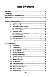
Table of Contents Box Contents ...6 Optional Items...6 GA-EG41MF-US2H Motherboard Layout 7 Block Diagram...8 Chapter 1 Hardware Installation 9 1-1 Installation Precautions 9 1-2 Product Specifications 10 1-3 Installing the CPU and CPU Cooler 13 1-3-1 Installing the CPU 13 1-3-2 Installing the CPU ...
Table of Contents Box Contents ...6 Optional Items...6 GA-EG41MF-US2H Motherboard Layout 7 Block Diagram...8 Chapter 1 Hardware Installation 9 1-1 Installation Precautions 9 1-2 Product Specifications 10 1-3 Installing the CPU and CPU Cooler 13 1-3-1 Installing the CPU 13 1-3-2 Installing the CPU ...

Manual
Page 6
Box Contents GA-EG41MF-US2H motherboard Motherboard driver disk User's Manual One IDE cable Two SATA 3Gb/s cables I/O Shield • The box contents above are subject to change without notice. • The motherboard image is for reference only and the actual items shall depend on the product package you obtain. Optional Items Floppy Disk Drive cable (Part...
Box Contents GA-EG41MF-US2H motherboard Motherboard driver disk User's Manual One IDE cable Two SATA 3Gb/s cables I/O Shield • The box contents above are subject to change without notice. • The motherboard image is for reference only and the actual items shall depend on the product package you obtain. Optional Items Floppy Disk Drive cable (Part...
Manual
Page 7
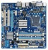
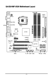
GA-EG41MF-US2H Motherboard Layout KB_MS PHASE LED IT8718 ATX_12V LGA775 FDD VGA LAN DVI HDMI Level Shifter OPTICAL Level Shifter USB_1394 BATTERY USB AUDIO F_AUDIO CPU_FAN PCIE_1 RTL8111C/D PCIE_16 PCI1 SPDIF_O PCI2 CODEC CD_IN SPDIF_I COMA GA-EG41MF-US2H Intel® G41 B_BIOS M_BIOS TSB43AB23 Intel® ICH7 DDR2_1 DDR2_2 DDR2_3 DDR2_4 IDE ATX SYS_FAN SATA2_1 SATA2_3 CI SATA2_0 SATA2_2 CLR_CMOS F1_1394 F_USB1 F_USB2 PWR_LED F_PANEL - 7 -
GA-EG41MF-US2H Motherboard Layout KB_MS PHASE LED IT8718 ATX_12V LGA775 FDD VGA LAN DVI HDMI Level Shifter OPTICAL Level Shifter USB_1394 BATTERY USB AUDIO F_AUDIO CPU_FAN PCIE_1 RTL8111C/D PCIE_16 PCI1 SPDIF_O PCI2 CODEC CD_IN SPDIF_I COMA GA-EG41MF-US2H Intel® G41 B_BIOS M_BIOS TSB43AB23 Intel® ICH7 DDR2_1 DDR2_2 DDR2_3 DDR2_4 IDE ATX SYS_FAN SATA2_1 SATA2_3 CI SATA2_0 SATA2_2 CLR_CMOS F1_1394 F_USB1 F_USB2 PWR_LED F_PANEL - 7 -

Manual
Page 9
... supply has been turned off. • Before turning on the power, make sure they are connected tightly and securely. • When handling the motherboard, avoid touching any installation steps or have a problem related to the use of the product, please consult a certified computer technician. - 9 - ... computer system on an uneven surface. • Do not place the computer system in a high-temperature environment. • Turning on the motherboard, make sure the power supply voltage has been set according to the local voltage standard. • Before using the product, please verify that...
... supply has been turned off. • Before turning on the power, make sure they are connected tightly and securely. • When handling the motherboard, avoid touching any installation steps or have a problem related to the use of the product, please consult a certified computer technician. - 9 - ... computer system on an uneven surface. • Do not place the computer system in a high-temperature environment. • Turning on the motherboard, make sure the power supply voltage has been set according to the local voltage standard. • Before using the product, please verify that...
Manual
Page 10
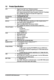
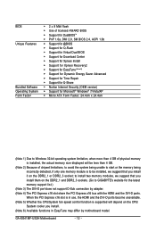
... supporting up to 8 GB of system memory (Note 1) Dual channel memory architecture (Note 2) Support for DDR2 800/667 MHz memory modules (Go to GIGABYTE's website for the latest memory support list.) North Bridge: - 1 x D-Sub port - 1 x DVI-D port (Note 3) (Note 4) - 1 x HDMI port (... Bridge Up to 8 USB 2.0/1.1 ports (4 on the back panel, 1 via the USB brackets connected to the internal IEEE 1394a header) GA-EG41MF-US2H Motherboard - 10 - TSB43AB23 chip Up to 2 IEEE 1394a ports (1 on the back panel, 4 via the IEEE 1394a bracket connected to the...
... supporting up to 8 GB of system memory (Note 1) Dual channel memory architecture (Note 2) Support for DDR2 800/667 MHz memory modules (Go to GIGABYTE's website for the latest memory support list.) North Bridge: - 1 x D-Sub port - 1 x DVI-D port (Note 3) (Note 4) - 1 x HDMI port (... Bridge Up to 8 USB 2.0/1.1 ports (4 on the back panel, 1 via the USB brackets connected to the internal IEEE 1394a header) GA-EG41MF-US2H Motherboard - 10 - TSB43AB23 chip Up to 2 IEEE 1394a ports (1 on the back panel, 4 via the IEEE 1394a bracket connected to the...
Manual
Page 12
... is supported will be less than 4 GB of physical memory is installed, the actual memory size displayed will depend on the DDR2_1 or DDR2_3 socket; GA-EG41MF-US2H Motherboard - 12 - to Windows 32-bit operating system limitation, when more than 4 GB. (Note 2) Because of licensed AWARD BIOS Support for ...the CPU/System fan speed control function is to be installed, we suggest that you install them on the DDR2_1 and DDR2_3 sockets. (Go to GIGABYTE's website for Microsoft® Windows® 7/Vista/XP Micro ATX Form Factor; 24.4cm x 24.4cm (Note 1) Due to install...
... is supported will be less than 4 GB of physical memory is installed, the actual memory size displayed will depend on the DDR2_1 or DDR2_3 socket; GA-EG41MF-US2H Motherboard - 12 - to Windows 32-bit operating system limitation, when more than 4 GB. (Note 2) Because of licensed AWARD BIOS Support for ...the CPU/System fan speed control function is to be installed, we suggest that you install them on the DDR2_1 and DDR2_3 sockets. (Go to GIGABYTE's website for Microsoft® Windows® 7/Vista/XP Micro ATX Form Factor; 24.4cm x 24.4cm (Note 1) Due to install...

Manual
Page 13
...; Set the CPU host frequency in accordance with the CPU specifications. Locate the alignment keys on the motherboard CPU socket and the notches on the CPU - 13 - mended that the motherboard supports the CPU. (Go to GIGABYTE's website for the peripherals. If you wish to set beyond the standard specifications, please do so...
...; Set the CPU host frequency in accordance with the CPU specifications. Locate the alignment keys on the motherboard CPU socket and the notches on the CPU - 13 - mended that the motherboard supports the CPU. (Go to GIGABYTE's website for the peripherals. If you wish to set beyond the standard specifications, please do so...

Manual
Page 14
... one marking (triangle) with the pin one corner of the CPU socket (or you may align the CPU notches with your thumb and index fingers. GA-EG41MF-US2H Motherboard - 14 - Follow the steps below to turn off the computer and unplug the power cord from the load plate. (To protect the CPU socket, always...
... one marking (triangle) with the pin one corner of the CPU socket (or you may align the CPU notches with your thumb and index fingers. GA-EG41MF-US2H Motherboard - 14 - Follow the steps below to turn off the computer and unplug the power cord from the load plate. (To protect the CPU socket, always...

Manual
Page 15
... direction of arrow is to install.) Step 3: Place the cooler atop the CPU, aligning the four push pins through the pin holes on the motherboard. Use extreme care when removing the CPU cooler because the thermal grease/tape between the CPU cooler and CPU may damage the CPU. - 15... - Hardware Installation Check that the Male and Female push pins are joined closely. (Refer to correctly install the CPU cooler on the motherboard. (The following procedure uses Intel® boxed cooler as the picture above, the installation is to remove the cooler, on the contrary, is complete....
... direction of arrow is to install.) Step 3: Place the cooler atop the CPU, aligning the four push pins through the pin holes on the motherboard. Use extreme care when removing the CPU cooler because the thermal grease/tape between the CPU cooler and CPU may damage the CPU. - 15... - Hardware Installation Check that the Male and Female push pins are joined closely. (Refer to correctly install the CPU cooler on the motherboard. (The following procedure uses Intel® boxed cooler as the picture above, the installation is to remove the cooler, on the contrary, is complete....
Manual
Page 16
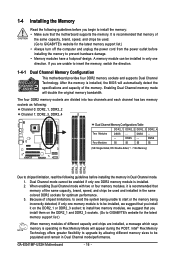
...Memory) DDR2_1 DDR2_2 DDR2_3 DDR2_4 Due to insert the memory, switch the direction. 1-4-1 Dual Channel Memory Configuration This motherboard provides four DDR2 memory sockets and supports Dual Channel Technology. Enabling Dual Channel memory mode will automatically detect the specifications...off the computer and unplug the power cord from the power outlet before installing the memory to GIGABYTE's website for optimum performance. 3. DS/SS - - - - GA-EG41MF-US2H Motherboard - 16 - Intel® Flex Memory Technology offers greater flexibility to upgrade by allowing different memory...
...Memory) DDR2_1 DDR2_2 DDR2_3 DDR2_4 Due to insert the memory, switch the direction. 1-4-1 Dual Channel Memory Configuration This motherboard provides four DDR2 memory sockets and supports Dual Channel Technology. Enabling Dual Channel memory mode will automatically detect the specifications...off the computer and unplug the power cord from the power outlet before installing the memory to GIGABYTE's website for optimum performance. 3. DS/SS - - - - GA-EG41MF-US2H Motherboard - 16 - Intel® Flex Memory Technology offers greater flexibility to upgrade by allowing different memory...

Manual
Page 17
Place the memory module on this motherboard. DDR2 DIMMs are not compatible to DDR DIMMs. Be sure to install DDR2 DIMMs on the socket. Notch DDR2 DIMM A DDR2 memory module has a notch, ...
Place the memory module on this motherboard. DDR2 DIMMs are not compatible to DDR DIMMs. Be sure to install DDR2 DIMMs on the socket. Notch DDR2 DIMM A DDR2 memory module has a notch, ...
Manual
Page 18
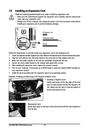
...Example: Installing and Removing a PCI Express Graphics Card: • Installing a Graphics Card: Gently push down on your expansion card(s). 7. GA-EG41MF-US2H Motherboard - 18 - 1-5 Installing an Expansion Card Read the following guidelines before installing an expansion card to correctly install your expansion card. •...securely seated in your card. Secure the card's metal bracket to install an expansion card: • Make sure the motherboard supports the expansion card. Install the driver provided with your expansion card in the slot. 3. Make sure the card...
...Example: Installing and Removing a PCI Express Graphics Card: • Installing a Graphics Card: Gently push down on your expansion card(s). 7. GA-EG41MF-US2H Motherboard - 18 - 1-5 Installing an Expansion Card Read the following guidelines before installing an expansion card to correctly install your expansion card. •...securely seated in your card. Secure the card's metal bracket to install an expansion card: • Make sure the motherboard supports the expansion card. Install the driver provided with your expansion card in the slot. 3. Make sure the card...

Manual
Page 19
.... Hardware Installation Connect a monitor that supports D-Sub connection to a back panel connector, first remove the cable from your device and then remove it from the motherboard. • When removing the cable, pull it side to side to connect a PS/2 keyboard. DVI-D Port The DVI-D port supports DVI-D specifictation. Please note the...
.... Hardware Installation Connect a monitor that supports D-Sub connection to a back panel connector, first remove the cable from your device and then remove it from the motherboard. • When removing the cable, pull it side to side to connect a PS/2 keyboard. DVI-D Port The DVI-D port supports DVI-D specifictation. Please note the...
Manual
Page 20
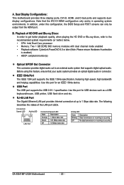
...for USB devices such as a USB keyboard/mouse, USB printer, USB flash drive and etc. Dual Display Configurations: This motherboard provides three display ports, DVI-D, HDMI, and D-Sub ports and supports dualdisplay configurations. IEEE 1394a Port The IEEE 1394 port...memory modules with dual channel mode enabled • Playback software: CyberLink PowerDVD 8.0 or later (Note: Please ensure Hardware Acceleration is occurring GA-EG41MF-US2H Motherboard - 20 - Connection/ Speed LED Activity LED LAN Port Connection/Speed LED: State Description Orange 1 Gbps data rate Green 100 Mbps ...
...for USB devices such as a USB keyboard/mouse, USB printer, USB flash drive and etc. Dual Display Configurations: This motherboard provides three display ports, DVI-D, HDMI, and D-Sub ports and supports dualdisplay configurations. IEEE 1394a Port The IEEE 1394 port...memory modules with dual channel mode enabled • Playback software: CyberLink PowerDVD 8.0 or later (Note: Please ensure Hardware Acceleration is occurring GA-EG41MF-US2H Motherboard - 20 - Connection/ Speed LED Activity LED LAN Port Connection/Speed LED: State Description Orange 1 Gbps data rate Green 100 Mbps ...

Manual
Page 22
... sure to the connector on the motherboard. Unplug the power cord from the power outlet to prevent damage to the devices. • After installing the device and before connecting external devices: • First make sure the device cable has been securely attached to turn off the devices and your computer. GA-EG41MF-US2H Motherboard - 22 -
... sure to the connector on the motherboard. Unplug the power cord from the power outlet to prevent damage to the devices. • After installing the device and before connecting external devices: • First make sure the device cable has been securely attached to turn off the devices and your computer. GA-EG41MF-US2H Motherboard - 22 -

Manual
Page 23
... power supply cable into pins under the protective cover when using a 2x12 power supply, remove the protective cover from the main power connector on the motherboard. Before connecting the power connector, first make sure the power supply is used that can withstand high power consumption be used (500W or greater). The...; The main power connector is compatible with power supplies with 2x10 power connectors. If a power supply is turned off and all the components on the motherboard. The power connector possesses a foolproof design. Hardware Installation
... power supply cable into pins under the protective cover when using a 2x12 power supply, remove the protective cover from the main power connector on the motherboard. Before connecting the power connector, first make sure the power supply is used that can withstand high power consumption be used (500W or greater). The...; The main power connector is compatible with power supplies with 2x10 power connectors. If a power supply is turned off and all the components on the motherboard. The power connector possesses a foolproof design. Hardware Installation

Manual
Page 24
..., be installed inside the chassis. For optimum heat dissipation, it in damage to connect a floppy disk drive. 3/4) CPU_FAN/SYS_FAN (Fan Headers) The motherboard has a 4-pin CPU fan header and a 4-pin system fan header (CPU_FAN/ SYS_FAN). Definition 1 GND 2 +12V/Speed Control CPU_FAN 3 Sense ...the ground wire). For purchasing the optional floppy disk drive cable, please contact the local dealer. 34 33 2 1 GA-EG41MF-US2H Motherboard - 24 - Most fan headers possess a foolproof insertion design. When connecting a fan cable, be sure to prevent your CPU and...
..., be installed inside the chassis. For optimum heat dissipation, it in damage to connect a floppy disk drive. 3/4) CPU_FAN/SYS_FAN (Fan Headers) The motherboard has a 4-pin CPU fan header and a 4-pin system fan header (CPU_FAN/ SYS_FAN). Definition 1 GND 2 +12V/Speed Control CPU_FAN 3 Sense ...the ground wire). For purchasing the optional floppy disk drive cable, please contact the local dealer. 34 33 2 1 GA-EG41MF-US2H Motherboard - 24 - Most fan headers possess a foolproof insertion design. When connecting a fan cable, be sure to prevent your CPU and...


