Manual
Page 1
GA-H67M-D2-B3 LGA1155 socket motherboard for Intel® Core™ i7 processors/ Intel® Core™ i5 processors/Intel® Core™ i3 processors/ Intel® Pentium® processors/Intel® Celeron® processors User's Manual Rev. 1101 12ME-H67MD2B-1101R
GA-H67M-D2-B3 LGA1155 socket motherboard for Intel® Core™ i7 processors/ Intel® Core™ i5 processors/Intel® Core™ i3 processors/ Intel® Pentium® processors/Intel® Celeron® processors User's Manual Rev. 1101 12ME-H67MD2B-1101R
Manual
Page 2
Motherboard GA-H67M-D2-B3 Jan. 28, 2011 Motherboard GA-H67M-D2-B3 Jan. 28, 2011
Motherboard GA-H67M-D2-B3 Jan. 28, 2011 Motherboard GA-H67M-D2-B3 Jan. 28, 2011
Manual
Page 3
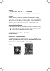
...manual are legally registered to their respective owners. For example, "REV: 1.0" means the revision of the motherboard is the property of GIGABYTE. Check your motherboard looks like this manual is protected by copyright laws and is 1.0. Example: The trademarks mentioned in this...reserved. For product-related information, check on our website at: http://www.gigabyte.com Identifying Your Motherboard Revision The revision number on your motherboard revision before updating motherboard BIOS, drivers, or when looking for technical information. Documentation Classifications In order...
...manual are legally registered to their respective owners. For example, "REV: 1.0" means the revision of the motherboard is the property of GIGABYTE. Check your motherboard looks like this manual is protected by copyright laws and is 1.0. Example: The trademarks mentioned in this...reserved. For product-related information, check on our website at: http://www.gigabyte.com Identifying Your Motherboard Revision The revision number on your motherboard revision before updating motherboard BIOS, drivers, or when looking for technical information. Documentation Classifications In order...
Manual
Page 4
Table of Contents Box Contents...6 Optional Items...6 GA-H67M-D2-B3 Motherboard Layout 7 GA-H67M-D2-B3 Motherboard Block Diagram 8 Chapter 1 Hardware Installation 9 1-1 Installation Precautions 9 1-2 Product Specifications 10 1-3 Installing the CPU and CPU Cooler 13 1-3-1 Installing the CPU 13 1-3-2 Installing the CPU Cooler ...
Table of Contents Box Contents...6 Optional Items...6 GA-H67M-D2-B3 Motherboard Layout 7 GA-H67M-D2-B3 Motherboard Block Diagram 8 Chapter 1 Hardware Installation 9 1-1 Installation Precautions 9 1-2 Product Specifications 10 1-3 Installing the CPU and CPU Cooler 13 1-3-1 Installing the CPU 13 1-3-2 Installing the CPU Cooler ...
Manual
Page 6
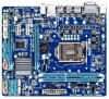
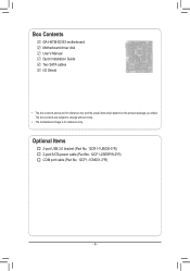
The box contents are for reference only. Optional Items 2-port USB 2.0 bracket (Part No. 12CR1-1UB030-5*R) 2-port SATA power cable (Part No. 12CF1-2SERPW-0*R) COM port cable (Part No. 12CF1-1CM001-3*R) - 6 - Box Contents GA-H67M-D2-B3 motherboard Motherboard driver disk User's Manual Quick Installation Guide Two SATA cables I/O Shield • The box contents above are subject to change without notice. • The motherboard image is for reference only and the actual items shall depend on the product package you obtain.
The box contents are for reference only. Optional Items 2-port USB 2.0 bracket (Part No. 12CR1-1UB030-5*R) 2-port SATA power cable (Part No. 12CF1-2SERPW-0*R) COM port cable (Part No. 12CF1-1CM001-3*R) - 6 - Box Contents GA-H67M-D2-B3 motherboard Motherboard driver disk User's Manual Quick Installation Guide Two SATA cables I/O Shield • The box contents above are subject to change without notice. • The motherboard image is for reference only and the actual items shall depend on the product package you obtain.
Manual
Page 7
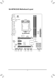
GA-H67M-D2-B3 Motherboard Layout KB_MS ATX_12V Level Shifter LGA1155 DVI VGA DDR3_1 DDR3_2 R_USB_2 R_USB_1 ATX USB30_20 USB_LAN AUDIO GA-H67M-D2-B3 PCIEX16 BAT CPU_FAN B_BIOS M_BIOS Realtek RTL8111E PCIEX1_1 PCIEX1_2 SYS_FAN CODEC PCIEX4 iTE IT8728 Intel® H67 CLR_CMOS SATA3_0 SATA3_1 SATA2_2 SATA2_3 SATA2_4 SATA2_5 F_AUDIO COMA COMB F_USB3 F_USB2 F_USB1 F_PANEL - 7 -
GA-H67M-D2-B3 Motherboard Layout KB_MS ATX_12V Level Shifter LGA1155 DVI VGA DDR3_1 DDR3_2 R_USB_2 R_USB_1 ATX USB30_20 USB_LAN AUDIO GA-H67M-D2-B3 PCIEX16 BAT CPU_FAN B_BIOS M_BIOS Realtek RTL8111E PCIEX1_1 PCIEX1_2 SYS_FAN CODEC PCIEX4 iTE IT8728 Intel® H67 CLR_CMOS SATA3_0 SATA3_1 SATA2_2 SATA2_3 SATA2_4 SATA2_5 F_AUDIO COMA COMB F_USB3 F_USB2 F_USB1 F_PANEL - 7 -
Manual
Page 8
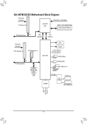
GA-H67M-D2-B3 Motherboard Block Diagram PCIe CLK (100 MHz) CPU CLK+/- (100 MHz) 1 PCI Express x16 LGA1155 CPU DDR3 1333/1066/800 MHz Dual Channel Memory PCI Express Bus x16 DMI Interface FDI Interface PCIe CLK (100 MHz) 1 PCI Express x4 2 PCI Express x1 x4 PCI Express Bus x1 x1 Realtek RTL8111E RJ45 LAN Intel® H67 DVI D-Sub Dual BIOS 4 SATA 3Gb/s 2 SATA 6Gb/s 14 USB 2.0/1.1 CODEC LPC Bus iTE IT8728 COM Ports PS/2 KB/Mouse MIC Line Out Line In - 8 -
GA-H67M-D2-B3 Motherboard Block Diagram PCIe CLK (100 MHz) CPU CLK+/- (100 MHz) 1 PCI Express x16 LGA1155 CPU DDR3 1333/1066/800 MHz Dual Channel Memory PCI Express Bus x16 DMI Interface FDI Interface PCIe CLK (100 MHz) 1 PCI Express x4 2 PCI Express x1 x4 PCI Express Bus x1 x1 Realtek RTL8111E RJ45 LAN Intel® H67 DVI D-Sub Dual BIOS 4 SATA 3Gb/s 2 SATA 6Gb/s 14 USB 2.0/1.1 CODEC LPC Bus iTE IT8728 COM Ports PS/2 KB/Mouse MIC Line Out Line In - 8 -
Manual
Page 9
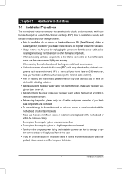
... please consult a certified computer technician. - 9 - Hardware Installation If you are connected tightly and securely. •• When handling the motherboard, avoid touching any installation steps or have a problem related to the use of electrostatic discharge (ESD). Prior to installation, carefully read the...uneven surface. •• Do not place the computer system in a high-temperature environment. •• Turning on the motherboard, make sure the power supply voltage has been set according to the local voltage standard. •• Before using the product...
... please consult a certified computer technician. - 9 - Hardware Installation If you are connected tightly and securely. •• When handling the motherboard, avoid touching any installation steps or have a problem related to the use of electrostatic discharge (ESD). Prior to installation, carefully read the...uneven surface. •• Do not place the computer system in a high-temperature environment. •• Turning on the motherboard, make sure the power supply voltage has been set according to the local voltage standard. •• Before using the product...
Manual
Page 12
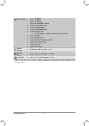
... Center ŠŠ Support for Xpress Install ŠŠ Support for Xpress Recovery2 ŠŠ Support for EasyTune * Available functions in EasyTune may differ by motherboard model. ŠŠ Support for Smart 6™ ŠŠ Support for Auto Green ŠŠ Support for eXtreme Hard Drive (X.H.D) ŠŠ Support for ON...
... Center ŠŠ Support for Xpress Install ŠŠ Support for Xpress Recovery2 ŠŠ Support for EasyTune * Available functions in EasyTune may differ by motherboard model. ŠŠ Support for Smart 6™ ŠŠ Support for Auto Green ŠŠ Support for eXtreme Hard Drive (X.H.D) ŠŠ Support for ON...
Manual
Page 13
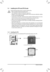
...the CPU Socket LGA1155 CPU Notch Notch Triangle Pin One Marking on the computer if the CPU cooler is not recommended that the motherboard supports the CPU. (Go to GIGABYTE's website for the peripherals. 1-3 Installing the CPU and CPU Cooler Read the following guidelines before you begin to install the ...(Or you may occur. •• Set the CPU host frequency in accordance with the CPU specifications. Locate the alignment keys on the motherboard CPU socket and the notches on the CPU. If you wish to set beyond the standard specifications, please do so according to your hardware ...
...the CPU Socket LGA1155 CPU Notch Notch Triangle Pin One Marking on the computer if the CPU cooler is not recommended that the motherboard supports the CPU. (Go to GIGABYTE's website for the peripherals. 1-3 Installing the CPU and CPU Cooler Read the following guidelines before you begin to install the ...(Or you may occur. •• Set the CPU host frequency in accordance with the CPU specifications. Locate the alignment keys on the motherboard CPU socket and the notches on the CPU. If you wish to set beyond the standard specifications, please do so according to your hardware ...
Manual
Page 14
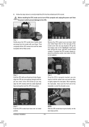
... the rear grip of the socket cover and use your thumb to lift up the front edge (next to correctly install the CPU into the motherboard CPU socket. To protect the CPU socket, always replace the protective socket cover when the CPU is not installed.) Step 3: Hold the CPU with your...
... the rear grip of the socket cover and use your thumb to lift up the front edge (next to correctly install the CPU into the motherboard CPU socket. To protect the CPU socket, always replace the protective socket cover when the CPU is not installed.) Step 3: Hold the CPU with your...
Manual
Page 15
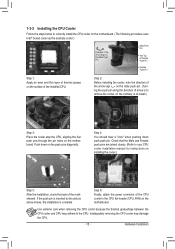
...through the pin holes on installing the cooler.) Step 5: After the installation, check the back of the motherboard. Step 4: You should hear a "click" when pushing down on the motherboard. Check that the Male and Female push pins are joined closely. (Refer to your CPU cooler installation ... the power connector of the installed CPU. 1-3-2 Installing the CPU Cooler Follow the steps below to correctly install the CPU cooler on the motherboard. (The following procedure uses Intel® boxed cooler as the picture above shows, the installation is complete. Use extreme care when removing ...
...through the pin holes on installing the cooler.) Step 5: After the installation, check the back of the motherboard. Step 4: You should hear a "click" when pushing down on the motherboard. Check that the Male and Female push pins are joined closely. (Refer to your CPU cooler installation ... the power connector of the installed CPU. 1-3-2 Installing the CPU Cooler Follow the steps below to correctly install the CPU cooler on the motherboard. (The following procedure uses Intel® boxed cooler as the picture above shows, the installation is complete. Use extreme care when removing ...
Manual
Page 16
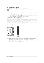
...of the same capacity, brand, speed, and chips be installed in Dual Channel mode. 1. Dual Channel mode cannot be used . (Go to GIGABYTE's website for the latest supported memory speeds and memory modules.) •• Always turn off the computer and unplug the power cord from the power...When enabling Dual Channel mode with two memory modules,it is recommended that memory of the memory. After the memory is recommended that the motherboard supports the memory. The two DDR3 memory sockets are unable to insert the memory, switch the direction. 1-4-1 Dual Channel Memory Configuration This...
...of the same capacity, brand, speed, and chips be installed in Dual Channel mode. 1. Dual Channel mode cannot be used . (Go to GIGABYTE's website for the latest supported memory speeds and memory modules.) •• Always turn off the computer and unplug the power cord from the power...When enabling Dual Channel mode with two memory modules,it is recommended that memory of the memory. After the memory is recommended that the motherboard supports the memory. The two DDR3 memory sockets are unable to insert the memory, switch the direction. 1-4-1 Dual Channel Memory Configuration This...
Manual
Page 17
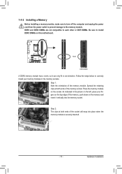
..., make sure to turn off the computer and unplug the power cord from the power outlet to prevent damage to install DDR3 DIMMs on this motherboard. Follow the steps below to correctly install your fingers on the socket.
..., make sure to turn off the computer and unplug the power cord from the power outlet to prevent damage to install DDR3 DIMMs on this motherboard. Follow the steps below to correctly install your fingers on the socket.
Manual
Page 18
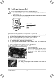
... off the computer and unplug the power cord from the power outlet before you begin to install an expansion card: •• Make sure the motherboard supports the expansion card. Example: Installing and Removing a PCI Express Graphics Card: •• Installing a Graphics Card: Gently push down on the card are completely...
... off the computer and unplug the power cord from the power outlet before you begin to install an expansion card: •• Make sure the motherboard supports the expansion card. Example: Installing and Removing a PCI Express Graphics Card: •• Installing a Graphics Card: Gently push down on the card are completely...
Manual
Page 19
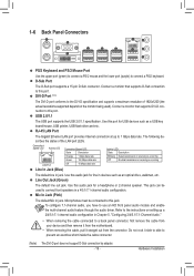
... Audio." •• When removing the cable connected to a back panel connector, first remove the cable from your device and then remove it from the motherboard. •• When removing the cable, pull it side to side to connect front speakers in devices such as a USB key board/mouse, USB printer...
... Audio." •• When removing the cable connected to a back panel connector, first remove the cable from your device and then remove it from the motherboard. •• When removing the cable, pull it side to side to connect front speakers in devices such as a USB key board/mouse, USB printer...
Manual
Page 20
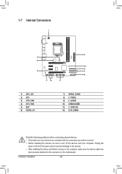
... sure your devices are compliant with the connectors you wish to connect. •• Before installing the devices, be sure to the connector on the motherboard. Hardware Installation - 20 -
... sure your devices are compliant with the connectors you wish to connect. •• Before installing the devices, be sure to the connector on the motherboard. Hardware Installation - 20 -
Manual
Page 21
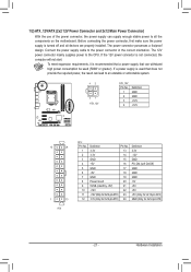
.... Connect the power supply cable to all devices are properly installed. If the 12V power connector is turned off and all the components on the motherboard. Before connecting the power connector, first make sure the power supply is not connected, the computer will not start.
.... Connect the power supply cable to all devices are properly installed. If the 12V power connector is turned off and all the components on the motherboard. Before connecting the power connector, first make sure the power supply is not connected, the computer will not start.
Manual
Page 22
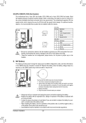
... headers to replace the battery by removing the battery: 1. Turn off your CPU and system from the battery holder and wait for 5 seconds.) 3. The motherboard supports CPU fan speed control, which requires the use a metal object like a screwdriver to connect it is the ground wire). Do not place a jumper ... your computer. •• Always turn off your - Hardware Installation - 22 - Most fan headers possess a foolproof insertion design. 3/4) CPU_FAN/SYS_FAN (Fan Headers) The motherboard has a 4-pin CPU fan header (CPU_FAN) and a 4-pin (SYS_FAN) fan header.
... headers to replace the battery by removing the battery: 1. Turn off your CPU and system from the battery holder and wait for 5 seconds.) 3. The motherboard supports CPU fan speed control, which requires the use a metal object like a screwdriver to connect it is the ground wire). Do not place a jumper ... your computer. •• Always turn off your - Hardware Installation - 22 - Most fan headers possess a foolproof insertion design. 3/4) CPU_FAN/SYS_FAN (Fan Headers) The motherboard has a 4-pin CPU fan header (CPU_FAN) and a 4-pin (SYS_FAN) fan header.

Manual
Page 25
...HD audio by default. For purchasing the optional COM port cable, please contact the local dealer. Incorrect connection between the module connector and the motherboard header will be present on both of the module con- If your chassis front panel audio module to Chapter 5, "Configuring 2/4/5.1/7.1-Channel Audio." .... You may connect your chassis provides an AC'97 front panel audio module, refer to the instructions on each wire instead of the motherboard header. If you want to mute the back panel audio (only supported when using an HD front panel audio module), refer to this...
...HD audio by default. For purchasing the optional COM port cable, please contact the local dealer. Incorrect connection between the module connector and the motherboard header will be present on both of the module con- If your chassis front panel audio module to Chapter 5, "Configuring 2/4/5.1/7.1-Channel Audio." .... You may connect your chassis provides an AC'97 front panel audio module, refer to the instructions on each wire instead of the motherboard header. If you want to mute the back panel audio (only supported when using an HD front panel audio module), refer to this...


