

User Manual
Page 2
...liquid is not covered by the warranty. 2 Any damage arising from the use of liquids other devices. 4. Malfunction arising from other than GIGABYTE™ Liquid Coolant is lower than the low water-level, the red light on the bottom of PCB will turn off automatically within four ...of the computer product, resulting in the tank is lower than the low water-level, the system will blink. (Please purchase GIGABYTE™ liquid coolant to improper installation. 11. The product's warranty label has been removed or damaged. 8. While removing the tubes for disassembly, please make sure ...
...liquid is not covered by the warranty. 2 Any damage arising from the use of liquids other devices. 4. Malfunction arising from other than GIGABYTE™ Liquid Coolant is lower than the low water-level, the red light on the bottom of PCB will turn off automatically within four ...of the computer product, resulting in the tank is lower than the low water-level, the system will blink. (Please purchase GIGABYTE™ liquid coolant to improper installation. 11. The product's warranty label has been removed or damaged. 8. While removing the tubes for disassembly, please make sure ...
User Manual
Page 3
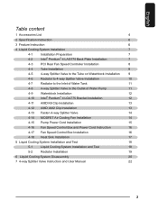
English Table content 1 Accessories List 4 2 Specification Instruction 6 3 Feature Instruction 6 4 Liquid Cooling System Installation 7 4-1 Installation Preparation 7 4-2 Intel® Pentium® 4 LAG775 Back Plate Installation 7 4-3 PCI Rear Fan Speed Controller Installation 8 4-4 Tube Installation 8 4-5 4-way Splitter Valve to the Tube on Waterblock Installation 9 4-6 Radiator to 4-way Splitter Valve Installation 10 4-7 Radiator to the Inlet of Water Tank 11 4-8 4-way Splitter Valve...
English Table content 1 Accessories List 4 2 Specification Instruction 6 3 Feature Instruction 6 4 Liquid Cooling System Installation 7 4-1 Installation Preparation 7 4-2 Intel® Pentium® 4 LAG775 Back Plate Installation 7 4-3 PCI Rear Fan Speed Controller Installation 8 4-4 Tube Installation 8 4-5 4-way Splitter Valve to the Tube on Waterblock Installation 9 4-6 Radiator to 4-way Splitter Valve Installation 10 4-7 Radiator to the Inlet of Water Tank 11 4-8 4-way Splitter Valve...

User Manual
Page 7
... memory 13.Wide range use for AMD K8/AM2;Intel® Pentium® 4 LGA 775. 4.Liquid Cooling System Installation Please follow the instruction. 4-1 Installation Preparation Please make sure the power of Intel® Pentium® 4 LAG775 CPU motherboard (as Figure b). Figure a... Figure b 7 English 5.Delicate sparkly blue LED light design tank; Tool needed: scissors, GIGABYTE™ coolant, grease, screwdriver. 4-2 Intel® Pentium® 4 LGA775 Back Plate Installation (For AMD series CPU, please ignore this step) 4-2-1 Take off the double-side sticker on the...
... memory 13.Wide range use for AMD K8/AM2;Intel® Pentium® 4 LGA 775. 4.Liquid Cooling System Installation Please follow the instruction. 4-1 Installation Preparation Please make sure the power of Intel® Pentium® 4 LAG775 CPU motherboard (as Figure b). Figure a... Figure b 7 English 5.Delicate sparkly blue LED light design tank; Tool needed: scissors, GIGABYTE™ coolant, grease, screwdriver. 4-2 Intel® Pentium® 4 LGA775 Back Plate Installation (For AMD series CPU, please ignore this step) 4-2-1 Take off the double-side sticker on the...

User Manual
Page 8
...valve (2) to fit all the components in the right position. Liquid Cooling System complete installation diagram. To get the right length for each parts of the tank 8 English 4-3 PCI Rear Fan Speed Controller Installation (as Figure a/b) 4-3-1 Place PCI rear fan speed controller to the back of ...the chassis (place on the lower PCI is recommended as Figure c.) Figure a Figure b Figure c 4-4 Tube Installation After measuring the distance between each tube, strongly recommend to the outlet of the cooling system, cut the tubes into five suitable sizes as ...
...valve (2) to fit all the components in the right position. Liquid Cooling System complete installation diagram. To get the right length for each parts of the tank 8 English 4-3 PCI Rear Fan Speed Controller Installation (as Figure a/b) 4-3-1 Place PCI rear fan speed controller to the back of ...the chassis (place on the lower PCI is recommended as Figure c.) Figure a Figure b Figure c 4-4 Tube Installation After measuring the distance between each tube, strongly recommend to the outlet of the cooling system, cut the tubes into five suitable sizes as ...
User Manual
Page 9
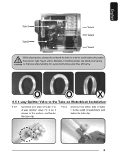
English Tube1 Tube2 Tube3 Tube4 Tube5 While placing tube, please do not bend the tube in the picture and fasten the tube clip. 4-5-2 Connect the other side of tube 1 to the outlet of tube 1 to avoid obstructing water flow efficiency. O O X 4-5 4-way Splitter Valve to the Tube on the tube while bending it shows in order to avoid obstructing water flow (as it to 4-way splitter valve (1) A as the right Figure under). Besides, if needed, please use bend proof spring on Waterblock Installation 4-5-1 Connect one side of waterblock and fasten the tube clip. 9
English Tube1 Tube2 Tube3 Tube4 Tube5 While placing tube, please do not bend the tube in the picture and fasten the tube clip. 4-5-2 Connect the other side of tube 1 to the outlet of tube 1 to avoid obstructing water flow efficiency. O O X 4-5 4-way Splitter Valve to the Tube on the tube while bending it shows in order to avoid obstructing water flow (as it to 4-way splitter valve (1) A as the right Figure under). Besides, if needed, please use bend proof spring on Waterblock Installation 4-5-1 Connect one side of waterblock and fasten the tube clip. 9

User Manual
Page 10
Figure a Figure b Figure c For GIGABYTE™ 3D Aurora, Triton or Poseidon series user, the tube can be threaded through the hole on the right in Figure c ) 10 If the 2 splitters ... 4-way splitter valve are available, please do not take off the cap and switch them to horizontal to avoid leakage. 4-6 4-6-1 Radiator to 4-way Splitter Valve Installation Thread Tube 3 through drainage inlet/outlet on the chassis.( as the two holes on PCI slot (as Figure a) to connect one side of tube 2 to...
Figure a Figure b Figure c For GIGABYTE™ 3D Aurora, Triton or Poseidon series user, the tube can be threaded through the hole on the right in Figure c ) 10 If the 2 splitters ... 4-way splitter valve are available, please do not take off the cap and switch them to horizontal to avoid leakage. 4-6 4-6-1 Radiator to 4-way Splitter Valve Installation Thread Tube 3 through drainage inlet/outlet on the chassis.( as the two holes on PCI slot (as Figure a) to connect one side of tube 2 to...

User Manual
Page 12
.... (as Figure b/c) Figure a Figure b Figure c 4-10 Intel® Pentium® 4 LGA775 Bracket Installation 4-10-1 Replace AMD K8 Bracket with Intel® Pentium® 4 LGA775 Bracket (accessory No. 11) ( Figure a ). Place the waterblock on the CPU surface evenly. Note: ... a) to take off the"CAUTION"sticker and apply the grease on the top of Intel® Pentium® 4 LGA775 CPU( Figure b ) and adjust the appropriate installation direction ( Figure c ).
.... (as Figure b/c) Figure a Figure b Figure c 4-10 Intel® Pentium® 4 LGA775 Bracket Installation 4-10-1 Replace AMD K8 Bracket with Intel® Pentium® 4 LGA775 Bracket (accessory No. 11) ( Figure a ). Place the waterblock on the CPU surface evenly. Note: ... a) to take off the"CAUTION"sticker and apply the grease on the top of Intel® Pentium® 4 LGA775 CPU( Figure b ) and adjust the appropriate installation direction ( Figure c ).
User Manual
Page 13
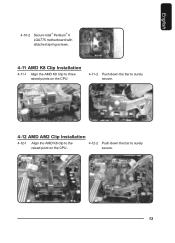
English 4-10-2 Secure Intel® Pentium® 4 LGA775 motherboard with attached spring screws. 4-11 AMD K8 Clip Installation 4-11-1 Align the AMD K8 Clip to three raised points on the CPU. 4-11-2 Push down the bar to surely secure. 4-12 AMD AM2 Clip Installation 4-12-1 Align the AMD K8 clip to the raised point on the CPU . 4-12-2 Push down the bar to surely secure. 13
English 4-10-2 Secure Intel® Pentium® 4 LGA775 motherboard with attached spring screws. 4-11 AMD K8 Clip Installation 4-11-1 Align the AMD K8 Clip to three raised points on the CPU. 4-11-2 Push down the bar to surely secure. 4-12 AMD AM2 Clip Installation 4-12-1 Align the AMD K8 clip to the raised point on the CPU . 4-12-2 Push down the bar to surely secure. 13

User Manual
Page 14
... tie to 2 power cord. If there is no trestle available, try to find an applicable place to fasten it. 4 -14 4-14-1 MOSFET Air Cooling Fan Installation Place MOSFET air cooling fan on the top of waterblock and make sure that four feet of the air cooling fan are secured on waterblock...
... tie to 2 power cord. If there is no trestle available, try to find an applicable place to fasten it. 4 -14 4-14-1 MOSFET Air Cooling Fan Installation Place MOSFET air cooling fan on the top of waterblock and make sure that four feet of the air cooling fan are secured on waterblock...

User Manual
Page 15
... of the tank, (as Figure a / b ) Figure a 4-15-5 Connect 4-pin power supply connector with the 4-pin pump cord connector. Figure b 15 English 4-15 Pump Power Cord Installation 4-15-1 Prepare Pump Power Cord a : 6-pin connector A b : female 2-pin connector c : male 2-pin connector d : 4-pin connector 4-15-2 4-15-3 Connect the Power SW (female 2-pin connector) from...
... of the tank, (as Figure a / b ) Figure a 4-15-5 Connect 4-pin power supply connector with the 4-pin pump cord connector. Figure b 15 English 4-15 Pump Power Cord Installation 4-15-1 Prepare Pump Power Cord a : 6-pin connector A b : female 2-pin connector c : male 2-pin connector d : 4-pin connector 4-15-2 4-15-3 Connect the Power SW (female 2-pin connector) from...

User Manual
Page 16
English 4-16 Fan Speed Control Box and Power Cord Instruction Fan Speed Control Box Socket Fan Speed Control Box PCI Rear Fan Speed Control Box Connector Power Cord Connect the other side of power cord with fan 1 to 2 power cord Radiator Fan Speed Control Box Connector Socket 4-17 Fan Speed Control Box Installation Tool needed: Fan Speed Control Box , Fan Speed Control Box Connect Line. 4-17-1 Thread the radiator fan connector through the hole of PCI rear fan speed controller. 4-17-2 Plug the connector from the PCI rear fan speed controller into the fan speed control box. 16
English 4-16 Fan Speed Control Box and Power Cord Instruction Fan Speed Control Box Socket Fan Speed Control Box PCI Rear Fan Speed Control Box Connector Power Cord Connect the other side of power cord with fan 1 to 2 power cord Radiator Fan Speed Control Box Connector Socket 4-17 Fan Speed Control Box Installation Tool needed: Fan Speed Control Box , Fan Speed Control Box Connect Line. 4-17-1 Thread the radiator fan connector through the hole of PCI rear fan speed controller. 4-17-2 Plug the connector from the PCI rear fan speed controller into the fan speed control box. 16

User Manual
Page 17
Figure a Figure b 4-18 Heat Sink Installation 4-18-1 Heat sink( 8 pcs) can be pasted on the small chips on the fan speed control box (as Figure a) and plug the other side of the power cord into the available 1 to lower the temperature. 17 English 4-17-3 Plug the radiator fan power cord into the fan speed control box. 4-17-4 To accomplish installation, plug the power cord of fan speed control box into the connector on the motherboard or VGA card to 2 socket (as Figure b).
Figure a Figure b 4-18 Heat Sink Installation 4-18-1 Heat sink( 8 pcs) can be pasted on the small chips on the fan speed control box (as Figure a) and plug the other side of the power cord into the available 1 to lower the temperature. 17 English 4-17-3 Plug the radiator fan power cord into the fan speed control box. 4-17-4 To accomplish installation, plug the power cord of fan speed control box into the connector on the motherboard or VGA card to 2 socket (as Figure b).
User Manual
Page 18
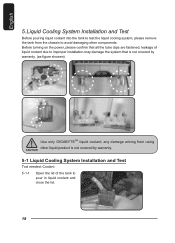
... the tank from using other liquid product is not covered by warranty. 5-1 Liquid Cooling System Installation and Test Tool needed: Coolant 5-1-1 Open the lid of liquid coolant due to improper installation may damage the system that all the tube clips are fastened; Before turning on the power..., please confirm that is not covered by warranty. (as figure showen) Use only GIGABYTE™ liquid coolant; any damage arising from the ...
... the tank from using other liquid product is not covered by warranty. 5-1 Liquid Cooling System Installation and Test Tool needed: Coolant 5-1-1 Open the lid of liquid coolant due to improper installation may damage the system that all the tube clips are fastened; Before turning on the power..., please confirm that is not covered by warranty. (as figure showen) Use only GIGABYTE™ liquid coolant; any damage arising from the ...

User Manual
Page 19
... coolant and than the low water-level. Turn on the power one more time and repeat this step until all coolant. Contact GIGABYTE™ dealers or GIGABYTE™ service center. 5-2 5-2-1 Radiator Installation Lock the radiator rack to the radiator with the following step 5-2 ; the radiator should be lay down flat to facilitate exhaust...
... coolant and than the low water-level. Turn on the power one more time and repeat this step until all coolant. Contact GIGABYTE™ dealers or GIGABYTE™ service center. 5-2 5-2-1 Radiator Installation Lock the radiator rack to the radiator with the following step 5-2 ; the radiator should be lay down flat to facilitate exhaust...
User Manual
Page 22
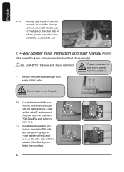
GIGABYTE™ blue eye and chipset waterblock Please make sure to avoid the leakage. connect one side of the tube with the first splitter on 4-way ... of VGA Blue Eye and fasten the tube clips. 22 English 6-1-9 Remove tube from PCI slot and be careful to turn off PC power before installation. 7-1 Remove the caps and tube clips from 4-way splitter valve. connect one side of the tube with the second splitter on 4-way splitter valve(1) and...
GIGABYTE™ blue eye and chipset waterblock Please make sure to avoid the leakage. connect one side of the tube with the first splitter on 4-way ... of VGA Blue Eye and fasten the tube clips. 22 English 6-1-9 Remove tube from PCI slot and be careful to turn off PC power before installation. 7-1 Remove the caps and tube clips from 4-way splitter valve. connect one side of the tube with the second splitter on 4-way splitter valve(1) and...