
Installation Guide
Page 2
GS-R114V Rack Mount Server Table of Content Safety, Care and Regulatory Information 4 Introduction 8 Contents Packages 8 WARNING 8 Chapter 1 Features Summary 9 Chapter 2 System Overview 11 Chapter 3 System Hardware ... PCI Expansion Card Installation 15 Step 3-6: Hard Disk Drive Installation 16 Step 3-7: FAN Duct Removal and Installation 17 Chapter 4 Appearance of GS-R114V 18 4-1: Front View of GS-R114V 18 4-2: Rear View of GS-R114V 19 4-3: Switch and LED Indicators Introduction 20 4-4: LAN LED Description 21 4-5 : Connector Icon Description 22 Chapter 5 Motherboard Layout &...
GS-R114V Rack Mount Server Table of Content Safety, Care and Regulatory Information 4 Introduction 8 Contents Packages 8 WARNING 8 Chapter 1 Features Summary 9 Chapter 2 System Overview 11 Chapter 3 System Hardware ... PCI Expansion Card Installation 15 Step 3-6: Hard Disk Drive Installation 16 Step 3-7: FAN Duct Removal and Installation 17 Chapter 4 Appearance of GS-R114V 18 4-1: Front View of GS-R114V 18 4-2: Rear View of GS-R114V 19 4-3: Switch and LED Indicators Introduction 20 4-4: LAN LED Description 21 4-5 : Connector Icon Description 22 Chapter 5 Motherboard Layout &...

Installation Guide
Page 3
Table of Content Advanced 33 Memory Configuration ...34 PCI Configuration ...35 I/O Device Configuration 37 Advanced Chipset Control 42 Hardware Monitor ...44 Security ...46 Server ...48 System Management ...49 Console Redirection ...50 Boot ...53 Exit ...54 Chapter 6 Driver Installation 58 A.Intel Chipset Software Installation Utilities 58 B.Intel LAN Driver Installation 60 C.Intel Host RAID Driver Installation 62 D.VGA ES100 Driver Installation 64 E.DirectX 9.0 Driver Installation 65 Chapter 7 Appendix 66 7-1: Acronyms ...66 3
Table of Content Advanced 33 Memory Configuration ...34 PCI Configuration ...35 I/O Device Configuration 37 Advanced Chipset Control 42 Hardware Monitor ...44 Security ...46 Server ...48 System Management ...49 Console Redirection ...50 Boot ...53 Exit ...54 Chapter 6 Driver Installation 58 A.Intel Chipset Software Installation Utilities 58 B.Intel LAN Driver Installation 60 C.Intel Host RAID Driver Installation 62 D.VGA ES100 Driver Installation 64 E.DirectX 9.0 Driver Installation 65 Chapter 7 Appendix 66 7-1: Acronyms ...66 3
Installation Guide
Page 4
... outlet. There may be operated only from lightning. 4 Do not block or cover these openings. Retain all safety and operating instructions for your area. GS-R114V Rack Mount Server Safety, Care and Regulatory Information Important safety information Read and follow all instructions marked on the product and in the documentation before removing covers...
... outlet. There may be operated only from lightning. 4 Do not block or cover these openings. Retain all safety and operating instructions for your area. GS-R114V Rack Mount Server Safety, Care and Regulatory Information Important safety information Read and follow all instructions marked on the product and in the documentation before removing covers...

Installation Guide
Page 6
... equipment, or equipment malfunctions, may give you will operate to party lines or coin-telephone service. The customer should be made by the supplier. GS-R114V Rack Mount Server Your telephone company may make such connections themselves, but should contact the appropriate electric inspection authority, or electrician, as set out in the radio...
... equipment, or equipment malfunctions, may give you will operate to party lines or coin-telephone service. The customer should be made by the supplier. GS-R114V Rack Mount Server Your telephone company may make such connections themselves, but should contact the appropriate electric inspection authority, or electrician, as set out in the radio...

Installation Guide
Page 8
... Integrated Circuit (IC) chips. If you plug in the system, please contact your system. Using the following checklist to Gigabyte GS-R114L Rack mount Server System Installation Guide. If any component is switched off before handling computer components. FAN Duct x 1 ; ; GA-4MPSV... Motherboard (Installed) GSMT User's Manual CPU Heat Sink x 1 Silm type CD-ROM drive (Installed) GS-R114V System Installation Guide Driver CD for the GS-R114L ...
... Integrated Circuit (IC) chips. If you plug in the system, please contact your system. Using the following checklist to Gigabyte GS-R114L Rack mount Server System Installation Guide. If any component is switched off before handling computer components. FAN Duct x 1 ; ; GA-4MPSV... Motherboard (Installed) GSMT User's Manual CPU Heat Sink x 1 Silm type CD-ROM drive (Installed) GS-R114V System Installation Guide Driver CD for the GS-R114L ...
Installation Guide
Page 10
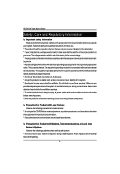
GS-R114V Rack Mount Server Super I/O Controller ITE IT8712FIX-A Super I/O Built-in I/O 1 x Serial port (COM) 2 x USB 2.0 dual-port connector (1 at front panel) 1 x VGA connector 2 x RJ45 LAN ports P/S 2 Keyboard and Mouse...after AC Back Wake On LAN ACPI 1.0B Compliant/ ACPI defined S1, S4, and S5 Software Mini BMC supported Server Management Functions: (Optional) BMC Chip NS IPMI 1.5 controller Failure Detection IPMI 1.5 specification of Server management Event Logging 32KB Nonvolatile Memory to Log System Failure Events Remote Management Follow the IPMI 1.5 specification of...
GS-R114V Rack Mount Server Super I/O Controller ITE IT8712FIX-A Super I/O Built-in I/O 1 x Serial port (COM) 2 x USB 2.0 dual-port connector (1 at front panel) 1 x VGA connector 2 x RJ45 LAN ports P/S 2 Keyboard and Mouse...after AC Back Wake On LAN ACPI 1.0B Compliant/ ACPI defined S1, S4, and S5 Software Mini BMC supported Server Management Functions: (Optional) BMC Chip NS IPMI 1.5 controller Failure Detection IPMI 1.5 specification of Server management Event Logging 32KB Nonvolatile Memory to Log System Failure Events Remote Management Follow the IPMI 1.5 specification of...

Installation Guide
Page 12
... Step 3-1: Chassis Removal and Installation Step 1 Loosen the thumbscrew from dust, humidity, and heat. Step 2 Push down the indentation located at two sides of the server. GS-R114V Rack Mount Server Chapter 3 System Hardware Installation Please observe the safety information in chapter "Important Safety Information" Do not expose the...
... Step 3-1: Chassis Removal and Installation Step 1 Loosen the thumbscrew from dust, humidity, and heat. Step 2 Push down the indentation located at two sides of the server. GS-R114V Rack Mount Server Chapter 3 System Hardware Installation Please observe the safety information in chapter "Important Safety Information" Do not expose the...
Installation Guide
Page 14
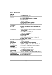
... screws. Firmly insert the DIMMinto the socket until the retaining clips snap back in the socket. 3. Unlock a DIMM socket by pressing the retaining clips outwards. 2. GS-R114V Rack Mount Server Step 3-3: Heat Sink Installation Step 1 Place the Heat Sink on the DIMM exactly match the notches in place. 4. Installation completed.
... screws. Firmly insert the DIMMinto the socket until the retaining clips snap back in the socket. 3. Unlock a DIMM socket by pressing the retaining clips outwards. 2. GS-R114V Rack Mount Server Step 3-3: Heat Sink Installation Step 1 Place the Heat Sink on the DIMM exactly match the notches in place. 4. Installation completed.
Installation Guide
Page 15
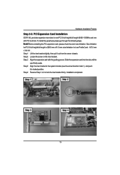
.... Step 3 Align the riser bracket to the system module (see the arrow direction mark 1), and push it out from the server chassis. Hardware Installation Process Step 3-5: PCI Expansion Card Installation GS-R114L provides expansion riser slots for one with the guiding groove. Step 1 Lift the riser bracket slightly, then pull it to...
.... Step 3 Align the riser bracket to the system module (see the arrow direction mark 1), and push it out from the server chassis. Hardware Installation Process Step 3-5: PCI Expansion Card Installation GS-R114L provides expansion riser slots for one with the guiding groove. Step 1 Lift the riser bracket slightly, then pull it to...
Installation Guide
Page 16
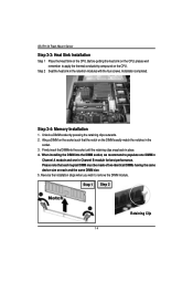
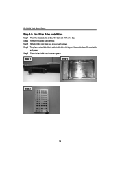
Connect cable and power. Step 4 To replace the hard drive blank, slide the blank into the bay until it with screws. Step 5 Place the hard disk into place. Step 1 Step 2 Step 3 16 Step 3 Slide hard disk into blank and secure it locks into the server system. Step 2 Remove the plastic hard disk tray. GS-R114V Rack Mount Server Step 3-6: Hard Disk Drive Installation Step 1 Press the release button and pull the blank out of the drive bay.
Connect cable and power. Step 4 To replace the hard drive blank, slide the blank into the bay until it with screws. Step 5 Place the hard disk into place. Step 1 Step 2 Step 3 16 Step 3 Slide hard disk into blank and secure it locks into the server system. Step 2 Remove the plastic hard disk tray. GS-R114V Rack Mount Server Step 3-6: Hard Disk Drive Installation Step 1 Press the release button and pull the blank out of the drive bay.
Installation Guide
Page 18
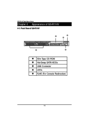
GS-R114V Rack Mount Server Chapter 4 Appearance of GS-R114V 4-1: Front View of GS-R114V Slim Type CD-ROM Hot-Swap SATA HDDs USB Connector LEDs RJ45 (For Console Redirection) 18
GS-R114V Rack Mount Server Chapter 4 Appearance of GS-R114V 4-1: Front View of GS-R114V Slim Type CD-ROM Hot-Swap SATA HDDs USB Connector LEDs RJ45 (For Console Redirection) 18

Installation Guide
Page 20
... Ready On/ Alarm Blink System Ready but deqraded, CPU Failed, DIMM Killed. HDD LAN1 Activity LAN2 Activity Identification Green Amber -Green Green -Green Green -Blue -- GS-R114V Rack Mount Server 4-3: Switch and LED Indicators Introduction HDD Fail Warning Status HDD Power/Sleep Name Power Status Color Green Green -Green Amber Amber --
... Ready On/ Alarm Blink System Ready but deqraded, CPU Failed, DIMM Killed. HDD LAN1 Activity LAN2 Activity Identification Green Amber -Green Green -Green Green -Blue -- GS-R114V Rack Mount Server 4-3: Switch and LED Indicators Introduction HDD Fail Warning Status HDD Power/Sleep Name Power Status Color Green Green -Green Amber Amber --
Installation Guide
Page 24
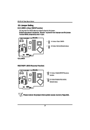
To clear CMOS, temporarily short 1-2 pin. 1 1-2 close: Clear CMOS 1 2-3 close: Normal (Default value) CLR_CMOS RECOVERY ( BIOS Recovery Function) 1 1-2 close: Enable BIOS Recovery function. 1 2-3 close: Disable this function. (Default value) Please remove the jumper when system access recovery flopp disk. 24 Default value doesn't include the "Shunter" to its default values by this jumper. GS-R114V Rack Mount Server 5-2: Jumper Setting CLR_CMOS ( (Clear CMOS Function) You may clear the CMOS data to prevent from improper use this jumper.
To clear CMOS, temporarily short 1-2 pin. 1 1-2 close: Clear CMOS 1 2-3 close: Normal (Default value) CLR_CMOS RECOVERY ( BIOS Recovery Function) 1 1-2 close: Enable BIOS Recovery function. 1 2-3 close: Disable this function. (Default value) Please remove the jumper when system access recovery flopp disk. 24 Default value doesn't include the "Shunter" to its default values by this jumper. GS-R114V Rack Mount Server 5-2: Jumper Setting CLR_CMOS ( (Clear CMOS Function) You may clear the CMOS data to prevent from improper use this jumper.

Installation Guide
Page 26
... the BIOS Setup Program. CONTROL KEYS Move to previous item Move to next item Move to the item in the right hand Main Menu - GS-R114V Rack Mount Server Chapter 6 BIOS Setup BIOS Setup is turned off. ENTERINGSETUP Power ON the computer and press immediately will allow you to the item in the...
... the BIOS Setup Program. CONTROL KEYS Move to previous item Move to next item Move to the item in the right hand Main Menu - GS-R114V Rack Mount Server Chapter 6 BIOS Setup BIOS Setup is turned off. ENTERINGSETUP Power ON the computer and press immediately will allow you to the item in the...
Installation Guide
Page 27
z Server Server additional features enabled/disabled setup menus. z Boot This setup page include all the items in standard compatible BIOS. z Main This setup page includes all the ...
z Server Server additional features enabled/disabled setup menus. z Boot This setup page include all the items in standard compatible BIOS. z Main This setup page includes all the ...
Installation Guide
Page 28
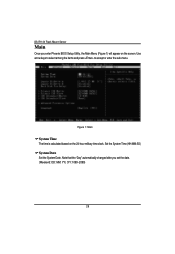
Note that the "Day" automatically changed after you enter Phoenix BIOS Setup Utility, the Main Menu (Figure 1) will appear on the 24-hour military time clock. Figure 1: Main System Time The time is calculated based on the screen. GS-R114V Rack Mount Server Main Once you set the date. (Weekend: DD: MM: YY) (YY: 1099~2099) 28 Use arrow keys to select among the items and press to accept or enter the sub-menu. Set the System Time (HH:MM:SS) System Date Set the System Date.
Note that the "Day" automatically changed after you enter Phoenix BIOS Setup Utility, the Main Menu (Figure 1) will appear on the 24-hour military time clock. Figure 1: Main System Time The time is calculated based on the screen. GS-R114V Rack Mount Server Main Once you set the date. (Weekend: DD: MM: YY) (YY: 1099~2099) 28 Use arrow keys to select among the items and press to accept or enter the sub-menu. Set the System Time (HH:MM:SS) System Date Set the System Date.

Installation Guide
Page 30
... Mode. Auto: The data transfer from and to the device occurs multiple sectors at a time. Enable this function to set all HDD parameters automatically. GS-R114V Rack Mount Server TYPE 1-39: Predefined types. Auto: Set parameters automatically. (Default Vaules) CD-ROM: Use for ATAPI CD-ROM drives or double click [Auto] to max...
... Mode. Auto: The data transfer from and to the device occurs multiple sectors at a time. Enable this function to set all HDD parameters automatically. GS-R114V Rack Mount Server TYPE 1-39: Predefined types. Auto: Set parameters automatically. (Default Vaules) CD-ROM: Use for ATAPI CD-ROM drives or double click [Auto] to max...
Installation Guide
Page 32
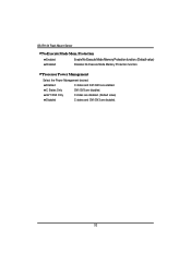
C States Only GV1/GV3 Only Disabled GV1/GV3 are disabled. 32 C states are disabled. (Default value) C states and GV1/GV3 are disabled. Processor Power Management Select the Power Management desired: Enabled C states and GV1/GV3 are enabled. Protection Enabled Enable No Execute Mode Memory Protection function. (Default value) Disabled Disables No Execute Mode Memory Protection function. GS-R114V Rack Mount Server No Execute Mode Mem.
C States Only GV1/GV3 Only Disabled GV1/GV3 are disabled. 32 C states are disabled. (Default value) C states and GV1/GV3 are disabled. Processor Power Management Select the Power Management desired: Enabled C states and GV1/GV3 are enabled. Protection Enabled Enable No Execute Mode Memory Protection function. (Default value) Disabled Disables No Execute Mode Memory Protection function. GS-R114V Rack Mount Server No Execute Mode Mem.

Installation Guide
Page 34
Disable this function. (Default value) 34 Disable this function. (Default value) Extend RAM Step Enabled Disabled Enable test extended memroy process. Save the changes and restart system. After rebooting system, the Memory Reset item will clear the memory error status. Memory Reset Yes No Select 'Yes', system will set to OS/DIMM Group 1,2,3,4 Status These category is display-only which is determined by POST (Power On Self Test) of the BIOS. GS-R114V Rack Mount Server Memory Configuration Figure 2-1: Memory Configuration Installed Memory/Available to 'No' automatically.
Disable this function. (Default value) 34 Disable this function. (Default value) Extend RAM Step Enabled Disabled Enable test extended memroy process. Save the changes and restart system. After rebooting system, the Memory Reset item will clear the memory error status. Memory Reset Yes No Select 'Yes', system will set to OS/DIMM Group 1,2,3,4 Status These category is display-only which is determined by POST (Power On Self Test) of the BIOS. GS-R114V Rack Mount Server Memory Configuration Figure 2-1: Memory Configuration Installed Memory/Available to 'No' automatically.

Installation Guide
Page 36
GS-R114V Rack Mount Server PCI Slot 1/2/3/4/5 Option ROM Enabled Disabled Enableing this item to initialize device expansion ROM. (Defualt value) Disable this function. 36
GS-R114V Rack Mount Server PCI Slot 1/2/3/4/5 Option ROM Enabled Disabled Enableing this item to initialize device expansion ROM. (Defualt value) Disable this function. 36