Manual
Page 1
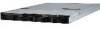
GS-R1233-RH 1U Rack Mount Server System Installation Guide AMD Opteron™ Socket F Dual Processor Motherboard Rev. 1.0
GS-R1233-RH 1U Rack Mount Server System Installation Guide AMD Opteron™ Socket F Dual Processor Motherboard Rev. 1.0

Manual
Page 2
... 2-5: PCI Expansion Card Installation 15 Step 2-6: Hard Disk Drive Installation 16 Step 2-7: FAN Duct Removal and Installation 17 Chapter 3 Appearance of GS-R1233-RH 18 3-1: Front View of GS-R1233-RH 18 3-2: Rear View of GS-R1233-RH 18 3-3: Front Bazel Switch and LED Indicators Introduction 19 3-4: LAN LED Description 20 3-5: Back plane board Information 21 3-6: Hard Disk Drive...
... 2-5: PCI Expansion Card Installation 15 Step 2-6: Hard Disk Drive Installation 16 Step 2-7: FAN Duct Removal and Installation 17 Chapter 3 Appearance of GS-R1233-RH 18 3-1: Front View of GS-R1233-RH 18 3-2: Rear View of GS-R1233-RH 18 3-3: Front Bazel Switch and LED Indicators Introduction 19 3-4: LAN LED Description 20 3-5: Back plane board Information 21 3-6: Hard Disk Drive...
Manual
Page 3
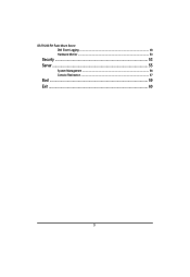
GS-R1233-RH Rack Mount Server DMI Event Logging ...48 Hardware Monitor ...50 Security ...53 Server ...55 System Management ...56 Console Redirection ...57 Boot ...59 Exit ...60 3
GS-R1233-RH Rack Mount Server DMI Event Logging ...48 Hardware Monitor ...50 Security ...53 Server ...55 System Management ...56 Console Redirection ...57 Boot ...59 Exit ...60 3
Manual
Page 4
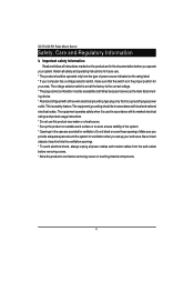
... when you set at the factory to cool before you provide adequate space around the system for ventilation. Do not block or cover these openings. GS-R1233-RH Rack Mount Server Safety, Care and Regulatory Information / Important safety information Read and follow all instructions marked on the product and in the documentation before...
... when you set at the factory to cool before you provide adequate space around the system for ventilation. Do not block or cover these openings. GS-R1233-RH Rack Mount Server Safety, Care and Regulatory Information / Important safety information Read and follow all instructions marked on the product and in the documentation before...
Manual
Page 5
Unauthorized changes or modifications could void the user's authority to meet FCC emission limits. Properly shielded and grounded cables and connectors must accept any radio or television interference caused by using other than recommended cables and connectors or by unauthorized changes or modifications to provide reasonable protection against harmful interference when the equipment is likely to cause harmful interference in a commercial environment. Neither the provider nor the manufacturer are designed to this equipment. / Federal Communications Commission (FCC...
Unauthorized changes or modifications could void the user's authority to meet FCC emission limits. Properly shielded and grounded cables and connectors must accept any radio or television interference caused by using other than recommended cables and connectors or by unauthorized changes or modifications to provide reasonable protection against harmful interference when the equipment is likely to cause harmful interference in a commercial environment. Neither the provider nor the manufacturer are designed to this equipment. / Federal Communications Commission (FCC...
Manual
Page 6
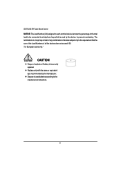
...; Danger of explosion if battery is incorrectly replaced. ™ Replace only with the same or equivalent type recommended by the device, to the manufacturer's instructions. 6 GS-R1233-RH Rack Mount Server NOTICE: The Load Number (LN) assigned to each terminal device denotes the percentage of used by the manufacturer. ™ Dispose of the...
...; Danger of explosion if battery is incorrectly replaced. ™ Replace only with the same or equivalent type recommended by the device, to the manufacturer's instructions. 6 GS-R1233-RH Rack Mount Server NOTICE: The Load Number (LN) assigned to each terminal device denotes the percentage of used by the manufacturer. ™ Dispose of the...
Manual
Page 7
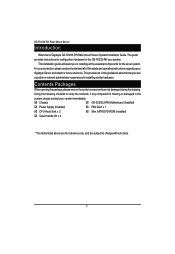
...during the shipping. The guide provides instructions for configuration hardware for reference only, and are subject to Gigabyte GS-R1233-RH Rack mount Server System Installation Guide. GS-R1233-RH Rack Mount Server Introduction Welcome to change without notice. 7 If any component is missing or damaged in...essential components for future reference. Case Handle Kit x 2 GA-3CESL2-RH Motherboard (Installed) FAN Duct x 1 Slim SATA DVD-ROM (Installed) * The items listed above are for the GS-R1233-RH your vendor immediately. ; Using the following checklist to verify the contents...
...during the shipping. The guide provides instructions for configuration hardware for reference only, and are subject to Gigabyte GS-R1233-RH Rack mount Server System Installation Guide. GS-R1233-RH Rack Mount Server Introduction Welcome to change without notice. 7 If any component is missing or damaged in...essential components for future reference. Case Handle Kit x 2 GA-3CESL2-RH Motherboard (Installed) FAN Duct x 1 Slim SATA DVD-ROM (Installed) * The items listed above are for the GS-R1233-RH your vendor immediately. ; Using the following checklist to verify the contents...
Manual
Page 8
GS-R1233-RH Rack Mount Server Chapter 1 Features Summary Motherboard Processor Supported Chipset System Memory: Memory Capacity Memory Type DIMM Size Error Correction: Expansion Slot SATA RAID controller Cooling Fans: Integrated LANs: Controller Integrated Graphics: Controller Graphics Memory Mass Storage System Super I/O Controller Built-in I/O System BIOS: y GA-3CESL2-RH y Support DualAMD OpteronTM 2000 series...
GS-R1233-RH Rack Mount Server Chapter 1 Features Summary Motherboard Processor Supported Chipset System Memory: Memory Capacity Memory Type DIMM Size Error Correction: Expansion Slot SATA RAID controller Cooling Fans: Integrated LANs: Controller Integrated Graphics: Controller Graphics Memory Mass Storage System Super I/O Controller Built-in I/O System BIOS: y GA-3CESL2-RH y Support DualAMD OpteronTM 2000 series...
Manual
Page 9
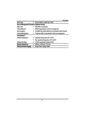
Introduction BIOS Type y Phoenix BIOS on 8Mb flash ROM Server Management Functions: (Optional device) BMC Chip y H8S IPMI 2.0 controller Failure Detection y IPMI 2.0 specification of Server management Event Logging y 9.216KB Nonvolatile Memory to Log System Failure Events Remote Management y Follow the IPMI 2.0 specification of Server management Environment Ambient Temperature y Operating Temperature: 5oC to 35oC y Non-operating Temperature: 0oC to 50oC Relative Humidity y 10-80% operating Humidity at 30o C System Dimention: y 430mm x 43.5mm x 710 mm Electrical Power Supply...
Introduction BIOS Type y Phoenix BIOS on 8Mb flash ROM Server Management Functions: (Optional device) BMC Chip y H8S IPMI 2.0 controller Failure Detection y IPMI 2.0 specification of Server management Event Logging y 9.216KB Nonvolatile Memory to Log System Failure Events Remote Management y Follow the IPMI 2.0 specification of Server management Environment Ambient Temperature y Operating Temperature: 5oC to 35oC y Non-operating Temperature: 0oC to 50oC Relative Humidity y 10-80% operating Humidity at 30o C System Dimention: y 430mm x 43.5mm x 710 mm Electrical Power Supply...
Manual
Page 10
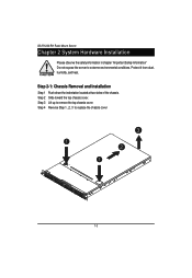
Step 3 Lift up to extreme environmental conditions. Step 2 Slide toward the top chassis cover. GS-R1233-RH Rack Mount Server Chapter 2 System Hardware Installation Please observe the safety information in chapter "Important Safety Information" Do not expose the server to remove the top chassis cover. Step 2-1: Chassis Removal and Installation Step 1 Push down the indentation located at two sides of the chassis. Protect it from dust, humidity, and heat. Step 4 Reverse Step 1, ,2, 3 to replace the chassis cover 3 1 2 1 10
Step 3 Lift up to extreme environmental conditions. Step 2 Slide toward the top chassis cover. GS-R1233-RH Rack Mount Server Chapter 2 System Hardware Installation Please observe the safety information in chapter "Important Safety Information" Do not expose the server to remove the top chassis cover. Step 2-1: Chassis Removal and Installation Step 1 Push down the indentation located at two sides of the chassis. Protect it from dust, humidity, and heat. Step 4 Reverse Step 1, ,2, 3 to replace the chassis cover 3 1 2 1 10
Manual
Page 11
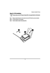
Step 2-2: CPU Installation Hardware Installation Process Please make sure the CPU type and speed that are supported by the motherboard. Step 3 Push the metal lever back into locked position. 3 2 1 11 Step 2 The CPU only fits in one orientation. Insert the CPU with the correct orientation. Step 1 Raise the metal locking lever on the socket.
Step 2-2: CPU Installation Hardware Installation Process Please make sure the CPU type and speed that are supported by the motherboard. Step 3 Push the metal lever back into locked position. 3 2 1 11 Step 2 The CPU only fits in one orientation. Insert the CPU with the correct orientation. Step 1 Raise the metal locking lever on the socket.
Manual
Page 12
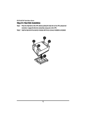
Step 2 Seat the heat sink in the retention modules with the four screws. Before putting the heat sink on the CPU, please well remember to apply the thermal conductivity compound on the CPU. Installation completed. 2 2 2 2 1 12 GS-R1233-RH Rack Mount Server Step 2-3: Heat Sink Installation Step 1 Place the Heat Sink on the CPU.
Step 2 Seat the heat sink in the retention modules with the four screws. Before putting the heat sink on the CPU, please well remember to apply the thermal conductivity compound on the CPU. Installation completed. 2 2 2 2 1 12 GS-R1233-RH Rack Mount Server Step 2-3: Heat Sink Installation Step 1 Place the Heat Sink on the CPU.
Manual
Page 13
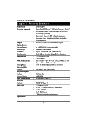
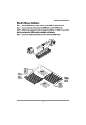
Insert the DIMM memory module vertically into the DIMM slot, and push it down. Close the plastic clip at both edges of the DIMM slots to remove the DIMM module. 2 1 2 DIMM_C2 DIMM_D2 DIMM_C1 DIMM_D1 DIMM_C4 DIMM_D4 DIMM_C3 DIMM_D3 CPU2 CPU1 DIMM_B3 DIMM_A3 DIMM_B4 DIMM_A4 DIMM_B1 DIMM_A1 DIMM_B2 DIMM_A2 13 Step 2. NOTE! DIMM must be populated in matched pairs. Reverse the installation steps when you wish to lock the DIMM module. Step 3. For dual-channel operation, DIMMs must be installed in order starting from DIMM_A1 or DIMM_C1 socket. Step 2-4: Memory ...
Insert the DIMM memory module vertically into the DIMM slot, and push it down. Close the plastic clip at both edges of the DIMM slots to remove the DIMM module. 2 1 2 DIMM_C2 DIMM_D2 DIMM_C1 DIMM_D1 DIMM_C4 DIMM_D4 DIMM_C3 DIMM_D3 CPU2 CPU1 DIMM_B3 DIMM_A3 DIMM_B4 DIMM_A4 DIMM_B1 DIMM_A1 DIMM_B2 DIMM_A2 13 Step 2. NOTE! DIMM must be populated in matched pairs. Reverse the installation steps when you wish to lock the DIMM module. Step 3. For dual-channel operation, DIMMs must be installed in order starting from DIMM_A1 or DIMM_C1 socket. Step 2-4: Memory ...
Manual
Page 14
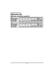
... (8DIMMs) DIMM_C4 Populate DIMM_D4 Populate DIMM_C3 Populate DIMM_D3 Populate DIMM_C2 Populate Populate DIMM_D2 Populate Populate DIMM_C1 Populate Populate Populate Populate DIMM_D1 Populate Populate Populate 14 GS-R1233-RH Rack Mount Server DIMM Population Table DIMM: Single or dual Rank Max.
... (8DIMMs) DIMM_C4 Populate DIMM_D4 Populate DIMM_C3 Populate DIMM_D3 Populate DIMM_C2 Populate Populate DIMM_D2 Populate Populate DIMM_C1 Populate Populate Populate Populate DIMM_D1 Populate Populate Populate 14 GS-R1233-RH Rack Mount Server DIMM Population Table DIMM: Single or dual Rank Max.
Manual
Page 15
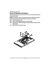
... expansion card into the slot until the card firmly seats. Before installing the expansion card, please check the card size limitation. GS-R1233-RH Rack Mount Server Step 2-5: PCI Expansion Card Installation GS-R1231-RH provides expansion riser slots for low profile riser card is 182mm; Step 2 Lift the riser bracket slightly, then pull it...
... expansion card into the slot until the card firmly seats. Before installing the expansion card, please check the card size limitation. GS-R1233-RH Rack Mount Server Step 2-5: PCI Expansion Card Installation GS-R1231-RH provides expansion riser slots for low profile riser card is 182mm; Step 2 Lift the riser bracket slightly, then pull it...
Manual
Page 16
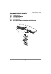
Step 4 Secure it locks into place. Connect cable and power. 1 2 3 4 4 16 Step 2 Pull the blank out of the drive bay. Step 3 Slide hard disk into the bay until it with screws. Step 5 Slide the blank into blank. Hardware Installation Process Step 2-6: Hard Disk Drive Installation Step 1 Press the release button.
Step 4 Secure it locks into place. Connect cable and power. 1 2 3 4 4 16 Step 2 Pull the blank out of the drive bay. Step 3 Slide hard disk into the bay until it with screws. Step 5 Slide the blank into blank. Hardware Installation Process Step 2-6: Hard Disk Drive Installation Step 1 Press the release button.

Manual
Page 17
Guiding groove 17 GS-R1233-RH Rack Mount Server Step 2-7: FAN Duct Removal and Installation Step 1 Align the fan duct with the guiding groove. Push down the fan duct into system ntil the its firmly seats.
Guiding groove 17 GS-R1233-RH Rack Mount Server Step 2-7: FAN Duct Removal and Installation Step 1 Align the fan duct with the guiding groove. Push down the fan duct into system ntil the its firmly seats.
Manual
Page 18
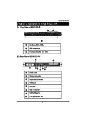
System Appearance Chapter 3 Appearance of GS-R1233-RH 3-1: Front View of GS-R1233-RH YZ X X Hot-Swap SATA HDDs Y USB connectors Z Front panel switch and LEDs 3-2: Rear View of GS-R1233-RH Y _ X Z\ [ ] ^ X Power cord Y Mouse connector Z Keyboard connector [ COM port \ VGA port ] USB connectors ^ RJ45 LAN ports _ Low-profile riser slot 18
System Appearance Chapter 3 Appearance of GS-R1233-RH 3-1: Front View of GS-R1233-RH YZ X X Hot-Swap SATA HDDs Y USB connectors Z Front panel switch and LEDs 3-2: Rear View of GS-R1233-RH Y _ X Z\ [ ] ^ X Power cord Y Mouse connector Z Keyboard connector [ COM port \ VGA port ] USB connectors ^ RJ45 LAN ports _ Low-profile riser slot 18

Manual
Page 19
... Ready but degraded, CPU Failed, DIMM Killed Critical Alarm: Critical Power Module Failure, Critical FANs Failure, Voltage (Power Supply) Critical Teemperature and Voltage System healthy. GS-R1233-RH Rack Mount Server 3-3: Front Bazel Switch and LED Indicators Introduction LAN1/2 Activities NMI switch System LED ID BTN&LED Reset switch HDD Power Name Power...
... Ready but degraded, CPU Failed, DIMM Killed Critical Alarm: Critical Power Module Failure, Critical FANs Failure, Voltage (Power Supply) Critical Teemperature and Voltage System healthy. GS-R1233-RH Rack Mount Server 3-3: Front Bazel Switch and LED Indicators Introduction LAN1/2 Activities NMI switch System LED ID BTN&LED Reset switch HDD Power Name Power...
Manual
Page 20
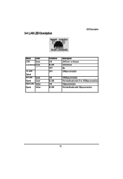
Speed 100 LAN Green Speed Green GbE LAN Yellow Speed Yellow Condition ON BLINK OFF OFF ON BLINK ON BLINK Description LAN Link / no Access LAN Access Idle 10Mbps connection 100Mbps connection Port identification with 10 or 100Mbps connection 1Gbps connection Port identification with 1Gbps connection 20 3-4: LAN LED Description LED Description Name Color LAN Green Link/Activity Green - 10 LAN -
Speed 100 LAN Green Speed Green GbE LAN Yellow Speed Yellow Condition ON BLINK OFF OFF ON BLINK ON BLINK Description LAN Link / no Access LAN Access Idle 10Mbps connection 100Mbps connection Port identification with 10 or 100Mbps connection 1Gbps connection Port identification with 1Gbps connection 20 3-4: LAN LED Description LED Description Name Color LAN Green Link/Activity Green - 10 LAN -