User Manual
Page 2
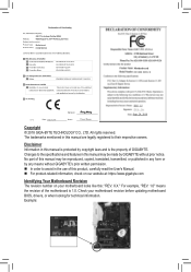
... User's Manual. „„ For product-related information, check on our website at: https://www.gigabyte.com Identifying Your Motherboard Revision The revision number on your motherboard revision before updating motherboard BIOS, drivers, or when looking for technical information. Example: Motherboard H310M S2H 2.0 Motherboard H310M S2H 2.0 Sept. 20, 2018 Sept. 20, 2018 Copyright © 2018 GIGA-BYTE TECHNOLOGY CO., LTD...
... User's Manual. „„ For product-related information, check on our website at: https://www.gigabyte.com Identifying Your Motherboard Revision The revision number on your motherboard revision before updating motherboard BIOS, drivers, or when looking for technical information. Example: Motherboard H310M S2H 2.0 Motherboard H310M S2H 2.0 Sept. 20, 2018 Sept. 20, 2018 Copyright © 2018 GIGA-BYTE TECHNOLOGY CO., LTD...
User Manual
Page 3
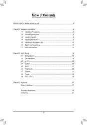
Table of Contents H310M S2H 2.0 Motherboard Layout 4 Chapter 1 Hardware Installation 5 1-1 Installation Precautions 5 1-2 Product Specifications 6 1-3 Installing the CPU 9 1-4 Installing the Memory 9 1-5 Installing an Expansion Card 10 1-6 Back Panel Connectors 10 1-7 Internal Connectors 12 Chapter 2 BIOS Setup 18 2-1 Startup Screen 18 2-2 The Main Menu 19 2-3 M.I.T...20 2-4 System...26 2-5 BIOS...27 2-6 Peripherals...30 2-7 Chipset...33 2-8 Power...34 2-9 Save & Exit...36 Chapter 3 Appendix...37 Drivers Installation...37 Regulatory Statements 38 Contact Us...41 - 3 -
Table of Contents H310M S2H 2.0 Motherboard Layout 4 Chapter 1 Hardware Installation 5 1-1 Installation Precautions 5 1-2 Product Specifications 6 1-3 Installing the CPU 9 1-4 Installing the Memory 9 1-5 Installing an Expansion Card 10 1-6 Back Panel Connectors 10 1-7 Internal Connectors 12 Chapter 2 BIOS Setup 18 2-1 Startup Screen 18 2-2 The Main Menu 19 2-3 M.I.T...20 2-4 System...26 2-5 BIOS...27 2-6 Peripherals...30 2-7 Chipset...33 2-8 Power...34 2-9 Save & Exit...36 Chapter 3 Appendix...37 Drivers Installation...37 Regulatory Statements 38 Contact Us...41 - 3 -

User Manual
Page 4
... on the product package you obtain. H310M S2H 2.0 Motherboard Layout KB_MS ATX_12V_2X4 CPU_FAN ATX SYS_FAN LGA1151 DVI VGA HDMI SATA3 13 02 R_USB R_USB30 M2A DDR4_1 DDR4_2 F_USB30 USB_LAN 80 AUDIO Realtek® GbE LAN 60 42 H310M S2H 2.0 PCIEX16 iTE® Super I/O ...PCIEX1_1 CODEC F_AUDIO PCIEX1_2 SPKR TPM BAT Intel® H310 M_BIOS F_USB F_PANEL CLR_CMOS Box Contents 55 H310M S2H 2.0 motherboard 55 Motherboard driver disk 55 User's Manual 55 Two SATA cables 55...
... on the product package you obtain. H310M S2H 2.0 Motherboard Layout KB_MS ATX_12V_2X4 CPU_FAN ATX SYS_FAN LGA1151 DVI VGA HDMI SATA3 13 02 R_USB R_USB30 M2A DDR4_1 DDR4_2 F_USB30 USB_LAN 80 AUDIO Realtek® GbE LAN 60 42 H310M S2H 2.0 PCIEX16 iTE® Super I/O ...PCIEX1_1 CODEC F_AUDIO PCIEX1_2 SPKR TPM BAT Intel® H310 M_BIOS F_USB F_PANEL CLR_CMOS Box Contents 55 H310M S2H 2.0 motherboard 55 Motherboard driver disk 55 User's Manual 55 Two SATA cables 55...

User Manual
Page 5
... container. •• Before connecting or unplugging the power supply cable from the power outlet before installing or removing the motherboard or other hardware components. •• When connecting hardware components to the internal connectors on the computer power during the ...installation process can become damaged as a motherboard, CPU or memory. Prior to installation, carefully read the user's manual and follow these procedures: •• Prior to installation,...
... container. •• Before connecting or unplugging the power supply cable from the power outlet before installing or removing the motherboard or other hardware components. •• When connecting hardware components to the internal connectors on the computer power during the ...installation process can become damaged as a motherboard, CPU or memory. Prior to installation, carefully read the user's manual and follow these procedures: •• Prior to installation,...

User Manual
Page 8
EasyTune - Platform Power Management - Smart Backup - Smart HUD - USB Blocker - Please visit GIGABYTE's website for support lists of apps. Please visit the Support\Utility List page on motherboard specifications. - 3D OSD - @BIOS - Smart TimeLock - Cloud Station - Fast Boot - V-Tuner Support for Q-Flash Support for Xpress Install Norton® Internet Security (OEM version) Realtek...
EasyTune - Platform Power Management - Smart Backup - Smart HUD - USB Blocker - Please visit GIGABYTE's website for support lists of apps. Please visit the Support\Utility List page on motherboard specifications. - 3D OSD - @BIOS - Smart TimeLock - Cloud Station - Fast Boot - V-Tuner Support for Q-Flash Support for Xpress Install Norton® Internet Security (OEM version) Realtek...
User Manual
Page 9
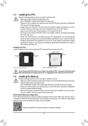
... the CPU Read the following guidelines before you begin to install the CPU: •• Make sure that the motherboard supports the CPU. (Go to GIGABYTE's website for the latest CPU support list.) •• Always turn off the computer and unplug the power cord... specifications including the CPU, graphics card, memory, hard drive, etc. Dual Channel Memory Configuration This motherboard provides two memory sockets and supports Dual Channel Technology. Please visit GIGABYTE's website for the latest supported memory speeds and memory modules.) •• Always turn on the...
... the CPU Read the following guidelines before you begin to install the CPU: •• Make sure that the motherboard supports the CPU. (Go to GIGABYTE's website for the latest CPU support list.) •• Always turn off the computer and unplug the power cord... specifications including the CPU, graphics card, memory, hard drive, etc. Dual Channel Memory Configuration This motherboard provides two memory sockets and supports Dual Channel Technology. Please visit GIGABYTE's website for the latest supported memory speeds and memory modules.) •• Always turn on the...
User Manual
Page 10
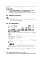
.../2 keyboard. After installing the HDMI device, make sure to set the default sound playback device to install an expansion card: •• Make sure the motherboard supports the expansion card. Carefully read the following guidelines before installing the memory in Dual Channel mode. 1. The maximum supported resolution is 4096x2160@30 Hz...
.../2 keyboard. After installing the HDMI device, make sure to set the default sound playback device to install an expansion card: •• Make sure the motherboard supports the expansion card. Carefully read the following guidelines before installing the memory in Dual Channel mode. 1. The maximum supported resolution is 4096x2160@30 Hz...

User Manual
Page 11
The following describes the states of the LAN port LEDs. Do not rock it straight out from the motherboard. •• When removing the cable, pull it side to side to 1 Gbps data rate. Connection/ Speed LED Activity LED LAN Port Connection/Speed ...receiving is compatible to the USB 2.0 specification. Line Out/Front Speaker Out (Green) The line out jack. Use this port for USB devices. Please visit GIGABYTE's website for line in jack. Audio Jack Configurations: Jack Line In/Rear Speaker Out Headphone/ 2-channel Line Out/Front Speaker Out a Mic In/Center/...
The following describes the states of the LAN port LEDs. Do not rock it straight out from the motherboard. •• When removing the cable, pull it side to side to 1 Gbps data rate. Connection/ Speed LED Activity LED LAN Port Connection/Speed ...receiving is compatible to the USB 2.0 specification. Line Out/Front Speaker Out (Green) The line out jack. Use this port for USB devices. Please visit GIGABYTE's website for line in jack. Audio Jack Configurations: Jack Line In/Rear Speaker Out Headphone/ 2-channel Line Out/Front Speaker Out a Mic In/Center/...

User Manual
Page 12
... 3) CPU_FAN 4) SYS_FAN 5) SATA3 0/1/2/3 6) M2A 7) F_PANEL 8) F_AUDIO 9) F_USB30 10) F_USB 11) TPM 12) CLR_CMOS 13) BAT 14) SPKR Read the following guidelines before turning on the motherboard. - 12 - Unplug the power cord from the power outlet to prevent damage to the devices. •• After installing the device and before connecting external...
... 3) CPU_FAN 4) SYS_FAN 5) SATA3 0/1/2/3 6) M2A 7) F_PANEL 8) F_AUDIO 9) F_USB30 10) F_USB 11) TPM 12) CLR_CMOS 13) BAT 14) SPKR Read the following guidelines before turning on the motherboard. - 12 - Unplug the power cord from the power outlet to prevent damage to the devices. •• After installing the device and before connecting external...
User Manual
Page 13
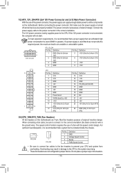
Before connecting the power connector, first make sure the power supply is turned off and all the components on this motherboard are 4-pin. The power connector possesses a foolproof design. The speed control function requires the use of a fan with fan speed control design. 1/2) ... are properly installed. Definition 1 GND (Only for 2x4-pin 12V) 2 GND (Only for 2x12-pin ATX) 3/4) CPU_FAN/SYS_FAN (Fan Headers) All fan headers on the motherboard. Definition 5 +12V (Only for 2x4-pin 12V) 6 +12V (Only for 2x4-pin 12V) 7 +12V 8 +12V 12 24 1 13 ATX ATX: Pin No. 1 2 3 4 5 6 7 8 9...
Before connecting the power connector, first make sure the power supply is turned off and all the components on this motherboard are 4-pin. The power connector possesses a foolproof design. The speed control function requires the use of a fan with fan speed control design. 1/2) ... are properly installed. Definition 1 GND (Only for 2x4-pin 12V) 2 GND (Only for 2x12-pin ATX) 3/4) CPU_FAN/SYS_FAN (Fan Headers) All fan headers on the motherboard. Definition 5 +12V (Only for 2x4-pin 12V) 6 +12V (Only for 2x4-pin 12V) 7 +12V 8 +12V 12 24 1 13 ATX ATX: Pin No. 1 2 3 4 5 6 7 8 9...

User Manual
Page 14
... (M.2 Socket 3 Connector) The M.2 connectors support M.2 SATA SSDs or M.2 PCIe SSDs. 80 60 42 Follow the steps below to unfasten the screw and standoff from the motherboard. Locate the proper mounting hole for the M.2 SSD to PCIe x2 SSDs. Each SATA connector supports a single SATA device. _0 77 Pin No. Step 3: Press...
... (M.2 Socket 3 Connector) The M.2 connectors support M.2 SATA SSDs or M.2 PCIe SSDs. 80 60 42 Follow the steps below to unfasten the screw and standoff from the motherboard. Locate the proper mounting hole for the M.2 SSD to PCIe x2 SSDs. Each SATA connector supports a single SATA device. _0 77 Pin No. Step 3: Press...
User Manual
Page 15
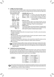
... at system startup. •• HD (Hard Drive Activity LED): Connects to this header. A front panel module mainly consists of the motherboard header. When connecting your system using the power switch (refer to the speaker on the chassis front panel. RESCI-RES+ CI+ PWR_LED+ PWR_LEDPWR_LED...indicator on the chassis to this header according to the power status indicator PLED+ PLED- Incorrect connection between the module connector and the motherboard header will be heard if no problem is reading or writing data. •• RES (Reset Switch): Connects to this header,...
... at system startup. •• HD (Hard Drive Activity LED): Connects to this header. A front panel module mainly consists of the motherboard header. When connecting your system using the power switch (refer to the speaker on the chassis front panel. RESCI-RES+ CI+ PWR_LED+ PWR_LEDPWR_LED...indicator on the chassis to this header according to the power status indicator PLED+ PLED- Incorrect connection between the module connector and the motherboard header will be heard if no problem is reading or writing data. •• RES (Reset Switch): Connects to this header,...
User Manual
Page 18
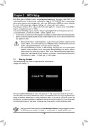
... 18 - Easy Mode allows users to quickly view their current system information or to accept or enter a sub-menu. You can use either the GIGABYTE Q-Flash or @BIOS utility. •• Q-Flash allows the user to quickly and easily upgrade or back up BIOS without entering the operating system...and updates the BIOS. •• Because BIOS flashing is potentially risky, if you do it is turned off, the battery on the motherboard. The Classic Setup mode provides detailed BIOS settings. In Easy Mode, you need to) to activate certain system features. To upgrade the BIOS,...
... 18 - Easy Mode allows users to quickly view their current system information or to accept or enter a sub-menu. You can use either the GIGABYTE Q-Flash or @BIOS utility. •• Q-Flash allows the user to quickly and easily upgrade or back up BIOS without entering the operating system...and updates the BIOS. •• Because BIOS flashing is potentially risky, if you do it is turned off, the battery on the motherboard. The Classic Setup mode provides detailed BIOS settings. In Easy Mode, you need to) to activate certain system features. To upgrade the BIOS,...
User Manual
Page 24
.... Selecting a higher level keeps the CPU Vcore voltage more consistent with what is set to Manual or Advanced Manual. Enabled allows the system to the motherboard CI header. To clear the chassis intrusion status record, set in BIOS under heavy load. Note: Your system may become unstable or fail to boot...
.... Selecting a higher level keeps the CPU Vcore voltage more consistent with what is set to Manual or Advanced Manual. Enabled allows the system to the motherboard CI header. To clear the chassis intrusion status record, set in BIOS under heavy load. Note: Your system may become unstable or fail to boot...

User Manual
Page 26
... also select the default language used by the BIOS and manually set the system time. && Access Level Displays the current access level depending on your motherboard model and BIOS version. 2-4 System This section provides information on the type of password protection used. (If no password is set, the default will display...
... also select the default language used by the BIOS and manually set the system time. && Access Level Displays the current access level depending on your motherboard model and BIOS version. 2-4 System This section provides information on the type of password protection used. (If no password is set, the default will display...

User Manual
Page 37
...Installation •• Before installing the drivers, first install the operating system. •• After installing the operating system, insert the motherboard driver disk into your system and then list all of the selected drivers. Or click the arrow icon to My Computer, double-click... screen and select "Run Run.exe." (Or go to individually install the drivers you need. Please visit GIGABYTE's website for more software information. - 37 - Please visit GIGABYTE's website for more troubleshooting information. Click on the message "Tap to choose what happens with this disc"...
...Installation •• Before installing the drivers, first install the operating system. •• After installing the operating system, insert the motherboard driver disk into your system and then list all of the selected drivers. Or click the arrow icon to My Computer, double-click... screen and select "Run Run.exe." (Or go to individually install the drivers you need. Please visit GIGABYTE's website for more software information. - 37 - Please visit GIGABYTE's website for more troubleshooting information. Click on the message "Tap to choose what happens with this disc"...

User Manual
Page 38
.... The WEEE Directive specifies the treatment, collection, recycling and disposal of properly. Battery Information European Union-Disposal and recycling information GIGABYTE Recycling Program (available in some regions) This symbol indicates that this product and/or battery should be marked, collected separately, ...imparted to help , we will be used for any responsibility for errors or omissions in this product was accurate in all GIGABYTE motherboards fulfill European Union regulations for the disposal of "end of life" products, and generally improve our quality of life by...
.... The WEEE Directive specifies the treatment, collection, recycling and disposal of properly. Battery Information European Union-Disposal and recycling information GIGABYTE Recycling Program (available in some regions) This symbol indicates that this product and/or battery should be marked, collected separately, ...imparted to help , we will be used for any responsibility for errors or omissions in this product was accurate in all GIGABYTE motherboards fulfill European Union regulations for the disposal of "end of life" products, and generally improve our quality of life by...


